front drive shaft ISUZU TROOPER 1998 Service User Guide
[x] Cancel search | Manufacturer: ISUZU, Model Year: 1998, Model line: TROOPER, Model: ISUZU TROOPER 1998Pages: 3573, PDF Size: 60.36 MB
Page 275 of 3573
COMPRESSOR OVERHAUL 1D Ð 19
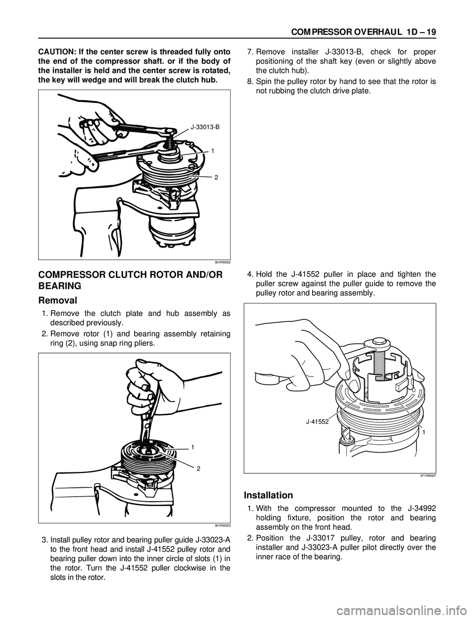
CAUTION: If the center screw is threaded fully onto
the end of the compressor shaft. or if the body of
the installer is held and the center screw is rotated,
the key will wedge and will break the clutch hub.7. Remove installer J-33013-B, check for proper
positioning of the shaft key (even or slightly above
the clutch hub).
8. Spin the pulley rotor by hand to see that the rotor is
not rubbing the clutch drive plate.
COMPRESSOR CLUTCH ROTOR AND/OR
BEARING
Removal
1. Remove the clutch plate and hub assembly as
described previously.
2. Remove rotor (1) and bearing assembly retaining
ring (2), using snap ring pliers.
3. Install pulley rotor and bearing puller guide J-33023-A
to the front head and install J-41552 pulley rotor and
bearing puller down into the inner circle of slots (1) in
the rotor. Turn the J-41552 puller clockwise in the
slots in the rotor.4. Hold the J-41552 puller in place and tighten the
puller screw against the puller guide to remove the
pulley rotor and bearing assembly.
Installation
1. With the compressor mounted to the J-34992
holding fixture, position the rotor and bearing
assembly on the front head.
2. Position the J-33017 pulley, rotor and bearing
installer and J-33023-A puller pilot directly over the
inner race of the bearing.
1
2 J-33013-B
901RW002
1
2
901RW003
J-41552
1
871RW007
Page 281 of 3573
COMPRESSOR OVERHAUL 1D Ð 25
1. Perform oil return operation.
2. Discharge and recover the refrigerant and remove
the compressor.
3. Drain the compressor oil and measure the extracted
oil.
4. Check the compressor oil for contamination.
5. Adjust the oil level as required.
6. Evacuate, charge and perform the oil return
operation.
7. Check the system operation.
Contamination of Compressor Oil
Unlike engine oil, no cleaning agent is added to the
compressor oil. Even if the compressor runs for a long
period of time (approximately one season), the oil never
becomes contaminated as long as there is nothing
wrong with the compressor or its method of use.
Inspect the extracted oil for any of the following
conditions:
·The capacity of the oil has increased.
·The oil has changed to red.
·Foreign substances, metal powder, etc., are present
in the oil.
If any of these conditions exists, the compressor
oil is contaminated. Whenever contaminated
compressor oil is discovered, the receiver/drier
must be replaced.
Oil Return Operation
There is close affinity between the oil and the
refrigerant. During normal operation, part of the oil
recirculates with the refrigerant in the system. When
checking the amount of oil in the system, or replacing
any component of the system, the compressor must be
run in advance for oil return operation. The procedure
is as follows:
1. Open all the doors and the engine hood.
2. Start the engine and air conditioning switch to "ON"
and set the fan control knob at its highest position.
3. Run the compressor for more than 20 minutes
between 800 and 1,000 rpm in order to operate the
system.
4. Stop the engine.
Replacement of Component Parts
When replacing the system component parts, supply
the following amount of oil to the component parts to be
installed.
Compressor Leak Testing (External and
Internal)
Bench-Check Procedure
1. Install test plate J-39893 on rear head of compressor.
2. Using Refrigerant Recovery System, attach center
hose of manifold gage set on charging station to a
refrigerant drum standing in an upright drum.
3. Connect charging station high and low pressure
lines to corresponding fittings on test plate J-39893.
Suction port (low-side) of compressor has large
internal opening. Discharge port (high-side) has
smaller internal opening into compressor and
deeper recess.
4. Open low pressure control, high pressure control
and refrigerant control on charging station to allow
refrigerant vapor to flow into compressor.
5. Using a leak detector, check for leaks at pressure
relief valve, rear head switch location, compressor
front and rear head seals, center cylinder seal,
through bolt head gaskets and compressor shaft
seal. After checking, shut off low pressure control
and high-pressure control on charging station.
6. If an external leak is present, perform the necessary
corrective measures and recheck for leaks to make
certain the leak has been connected.
7. Recover the refrigerant.
8. Disconnect both hoses from the test plate J-39893.
9. Add 90 ml (3 oz.) new PAG lubricant to the
compressor assembly. Rotate the complete
compressor assembly (not the crankshaft or drive
plate hub) slowly several turns to distribute oil to all
cylinder and piston areas.
10. Install a M9 ´1.25 threaded nut on the compressor
crankshaft if the drive plate and clutch assembly are
not installed.
11. Using a box-end wrench or socket and handle,
rotate the compressor crankshaft or clutch drive
plate on the crankshaft several turns to insure
piston assembly to cylinder wall lubrication.
12. Using Refrigerant Recovery System, connect the
charging station high-pressure line to the test plate
J-39893 high-side connector.
13. Using Refrigerant Recovery System, connect the
charging station low-pressure line to the low
pressure port of the test plate J-39893. Oil will drain
out of the compressor suction port if the compressor
is positioned with the suction port downward. (Component parts to be (Amount of Oil)
installed)
Evaporator 50 cc (1.7 fl. oz.)
Condenser 30 cc (1.0 fl. oz.)
Receiver/dryer 30 cc (1.0 fl. oz.)
Refrigerant line (one 10 cc (0.3 fl. oz.)
piece)
(Amount of oil drained (Charging amount of oil
from used compressor) to new compressor)
more than 90 cc same as drained amount
(3.0 fl.oz)
less than 90 cc (3.0 fl.oz) 90 cc (3.0 fl.oz)
Page 354 of 3573
This steering wheel and column repair section
covers the Supplemental Restraint System (SRS)
steering column. The following repair procedures
are specific to SRS Components. When servicing a
vehicle equipped with Supplemental Restraint
System, pay close attention to all WARNINGS and
CAUTIONS.
For detailed explanation about SRS, refer to Section
9J "SUPPLEMENTAL RESTRAINT SYSTEM (SRS)"
of manual.
The steering column has three important features in
addition to the steering function:
1. The column is energy absorbing, designed to
compress in a front-end collision to minimize
the possibility of injury to the driver of the
vehicle.
2. The ignition switch and lock are mounted
conveniently on the column.
3. With the column mounted lock, the ignition
and steering operation can be locked to
prevent theft of the vehicle.
The column may be disassembled and
reassembled. To insure the energy absorbing
action, it is important that the specified screws,
bolts and nuts be used only as designated and that
they are tightened to the specified torque.
When the column is removed from the vehicle, a
sharp blow on the end of steering shaft or shift
lever, leaning on the column assembly, or dropping
the assembly could shear or loosen the fasteners
that maintain column rigidity.
WARNING
THIS VEHICLE HAS A SUPPLEMENTAL RE-
STRAINT SYSTEM (SRS).REFER TO THE SRS
COMPONENT AND WIRING LOCATION VIEW
IN ORDER TO DETERMINE WHETHER YOU ARE
PERFORMING SERVICE ON OR NEAR THE SRS
COMPONENTS OR THE SRS WIRING. WHEN
YOU ARE PERFORMING SERVICE ON OR NEAR
THE SRS COMPONENTS OR THE SRS WIRING,
REFER TO THE SRS SERVICE INFORM ATION.
FAILURE TO FOLLOW WARNINGS COULD RE-
SULT IN POSSIBLE AIR BAG DEPLOYMENT,
PERSONAL INJURY, OR OTHERWISE UN-
NEEDED SRS SYSTEM REPAIRS.
SAFE HANDLING OF INFLATOR MODULES
REQUIRES FOLLOWING THE PROCEDURES
DESCRIBED BELOW FOR BOTH LIVE AND
DEPLOYED MODULES.
SAFETY PRECAUTIONS MUST BE FOLLOWEDWHEN HANDLING A DEPLOYED AIR BAG AS-
SEMBLY (AIR BAG). AFTER DEPLOYMENT,
THE AIR BAG ASSEMBLY (AIR BAG) SURFACE
MAY CONTAIN A SMALL AMOUNT OF SODIUM
HYDROXIDE, A BY-PRODUCT OF THE DEPLOY-
MENT REACTION, THAT IS IRRITATING TO THE
SKIN AND EYES.MOST OF THE POWDER ON
THE AIR BAG ASSEMBLY (AIR BAG) IS HARM-
LESS. AS A PRECAUTION, WEAR GLOVES
AND SAFETY GLASSES WHEN HANDLING A
DEPLOYED AIR BAG ASSEMBLY, AND WASH
YOUR HANDS WITH MILD SOAP AND WATER
AFTERWARDS.
WHEN CARRYING A LIVE AIR BAG ASSEMBLY,
MAKE SURE THE BAG AND TRIM COVER ARE
POINTED AWAY FROM YOU. NEVER CARRY
AN AIR BAG ASSEMBLY BY THE WIRES OR
CONNECTOR ON THE UNDERSIDE OF MODULE.
IN THE CASE OF AN ACCIDENTAL DEPLOY-
MENT, THE BAG WILL THEN DEPLOY WITH
MINIMAL CHANCE OF INJURY. WHEN PLACING
A LIVE AIR BAG ASSEMBLY ON A BENCH OR
OTHER SURFACE, ALWAYS FACE THE BAG AND
TRIM COVER UP, AWAY FROM THE SURFACE.
NEVER REST A STEERING COLUMN ASSEMBLY
ON THE STEERING WHEEL WITH THE AIR
BAG ASSEMBLY FACE DOWN AND COLUMN
VERTICAL.THIS IS NECESSARY SO THAT A
FREE SPACE IS PROVIDED TO ALLOW THE AIR
BAG ASSEMBLY TO EXPAND IN THE UNLIKELY
EVENT OF ACCIDENTAL DEPLOYMENT. OTHER-
WISE, PERSONAL INJURY COULD RESULT.
TO AVOID DEPLOYMENT WHEN TROUBLE
SHOOTING THE SRS SYSTEM, DO NOT USE
ELECTRICAL TEST EQUIPMENT, SUCH AS
BATTERY-POWERED OR A/C-POWERED VOLT-
METER, OHMMETER, ETC., OR ANY TYPE OF
ELECTRICAL EQUIPMENT OTHER THAN SPECI-
FIED IN THIS MANUAL. DO NOT USE A NON-
POWERED PROBE-TYPE TESTER.
INSTRUCTIONS IN THIS MANUAL MUST BE
FOLLOWED CAREFULLY, OTHERWISE PER-
SONAL INJURY MAY RESULT. 2A – 52 SUPPLEMENTAL RESTRAINT SYSTEM STEERING WHEEL & COLUMN
GENERAL DESCRIPTION
Page 360 of 3573
2A – 58 SUPPLEMENTAL RESTRAINT SYSTEM STEERING WHEEL & COLUMN
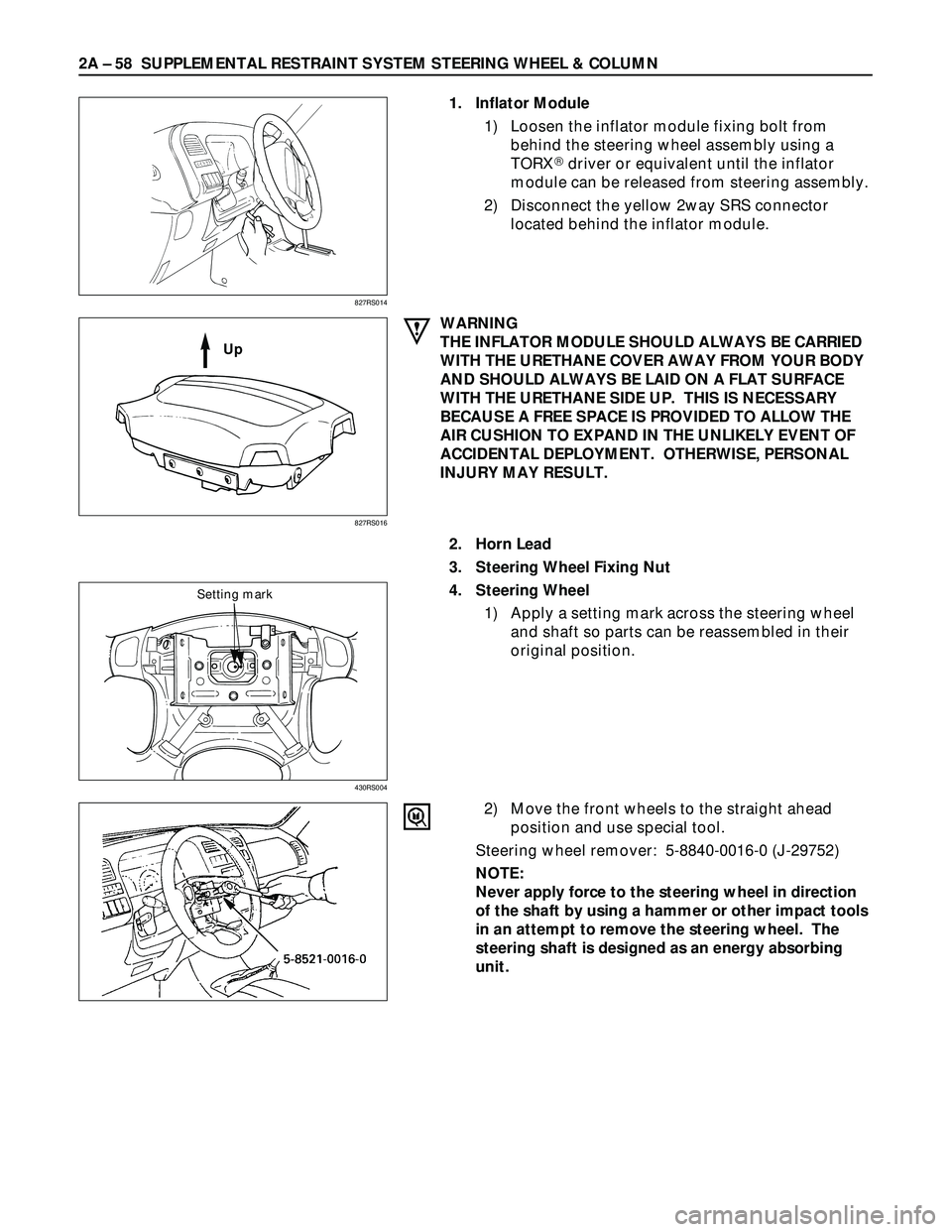
1. Inflator Module
1) Loosen the inflator module fixing bolt from
behind the steering wheel assembly using a
TORX
driver or equivalent until the inflator
module can be released from steering assembly.
2) Disconnect the yellow 2way SRS connector
located behind the inflator module.
WARNING
THE INFLATOR MODULE SHOULD ALWAYS BE CARRIED
WITH THE URETHANE COVER AWAY FROM YOUR BODY
AND SHOULD ALWAYS BE LAID ON A FLAT SURFACE
WITH THE URETHANE SIDE UP. THIS IS NECESSARY
BECAUSE A FREE SPACE IS PROVIDED TO ALLOW THE
AIR CUSHION TO EXPAND IN THE UNLIKELY EVENT OF
ACCIDENTAL DEPLOYMENT. OTHERWISE, PERSONAL
INJURY MAY RESULT.
2. Horn Lead
3. Steering Wheel Fixing Nut
4. Steering Wheel
1) Apply a setting mark across the steering wheel
and shaft so parts can be reassembled in their
original position.
2) Move the front wheels to the straight ahead
position and use special tool.
Steering wheel remover: 5-8840-0016-0 (J-29752)
NOTE:
Never apply force to the steering wheel in direction
of the shaft by using a hammer or other impact tools
in an attempt to remove the steering wheel. The
steering shaft is designed as an energy absorbing
unit.
827RS014
827RS016
430RS004
Up
Setting mark
Page 363 of 3573
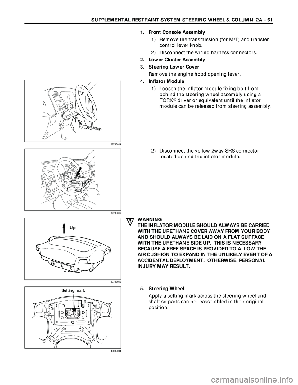
SUPPLEMENTAL RESTRAINT SYSTEM STEERING WHEEL & COLUMN 2A – 61
1. Front Console Assembly
1) Remove the transmission (for M/T) and transfer
control lever knob.
2) Disconnect the wiring harness connectors.
2. Lower Cluster Assembly
3. Steering Lower Cover
Remove the engine hood opening lever.
4. Inflator Module
1) Loosen the inflator module fixing bolt from
behind the steering wheel assembly using a
TORX
driver or equivalent until the inflator
module can be released from steering assembly.
2) Disconnect the yellow 2way SRS connector
located behind the inflator module.
WARNING
THE INFLATOR MODULE SHOULD ALWAYS BE CARRIED
WITH THE URETHANE COVER AWAY FROM YOUR BODY
AND SHOULD ALWAYS BE LAID ON A FLAT SURFACE
WITH THE URETHANE SIDE UP. THIS IS NECESSARY
BECAUSE A FREE SPACE IS PROVIDED TO ALLOW THE
AIR CUSHION TO EXPAND IN THE UNLIKELY EVENT OF A
ACCIDENTAL DEPLOYMENT. OTHERWISE, PERSONAL
INJURY MAY RESULT.
5. Steering Wheel
Apply a setting mark across the steering wheel and
shaft so parts can be reassembled in their original
position.
827RS014
827RS015
827RS016
Up
430RS004
Setting mark
Page 375 of 3573
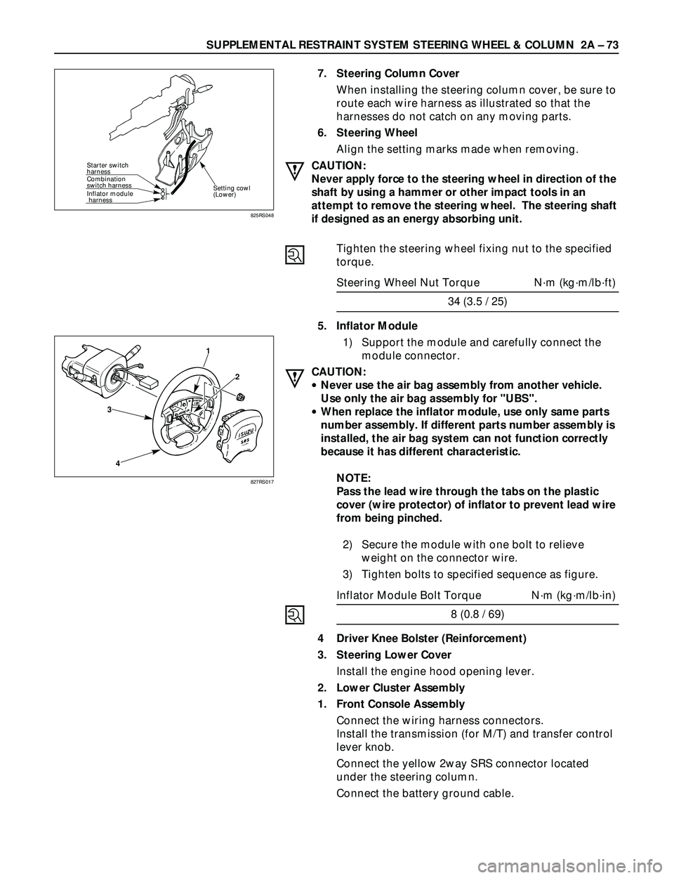
SUPPLEMENTAL RESTRAINT SYSTEM STEERING WHEEL & COLUMN 2A Ð 73
Starter switch
harness
Combination
switch harness
Inflator module
harness
Setting cowl
(Lower)
7. Steering Column Cover
When installing the steering column cover, be sure to
route each wire harness as illustrated so that the
harnesses do not catch on any moving parts.
6. Steering Wheel
Align the setting marks made when removing.
CAUTION:
Never apply force to the steering wheel in direction of the
shaft by using a hammer or other impact tools in an
attempt to remove the steering wheel. The steering shaft
if designed as an energy absorbing unit.
Tighten the steering wheel fixing nut to the specified
torque.
Steering Wheel Nut Torque Nám (kgám/lbáft)
34 (3.5 / 25)
5. Inflator Module
1) Support the module and carefully connect the
module connector.
CAUTION:
·Never use the air bag assembly from another vehicle.
Use only the air bag assembly for "UBS".
·When replace the inflator module, use only same parts
number assembly. If different parts number assembly is
installed, the air bag system can not function correctly
because it has different characteristic.
NOTE:
Pass the lead wire through the tabs on the plastic
cover (wire protector) of inflator to prevent lead wire
from being pinched.
2) Secure the module with one bolt to relieve
weight on the connector wire.
3) Tighten bolts to specified sequence as figure.
Inflator Module Bolt Torque Nám (kgám/lbáin)
8 (0.8 / 69)
4 Driver Knee Bolster (Reinforcement)
3. Steering Lower Cover
Install the engine hood opening lever.
2. Lower Cluster Assembly
1. Front Console Assembly
Connect the wiring harness connectors.
Install the transmission (for M/T) and transfer control
lever knob.
Connect the yellow 2way SRS connector located
under the steering column.
Connect the battery ground cable.
825RS048
3
41
2
827RS017
Page 378 of 3573
2A – 76 SUPPLEMENTAL RESTRAINT SYSTEM STEERING WHEEL & COLUMN
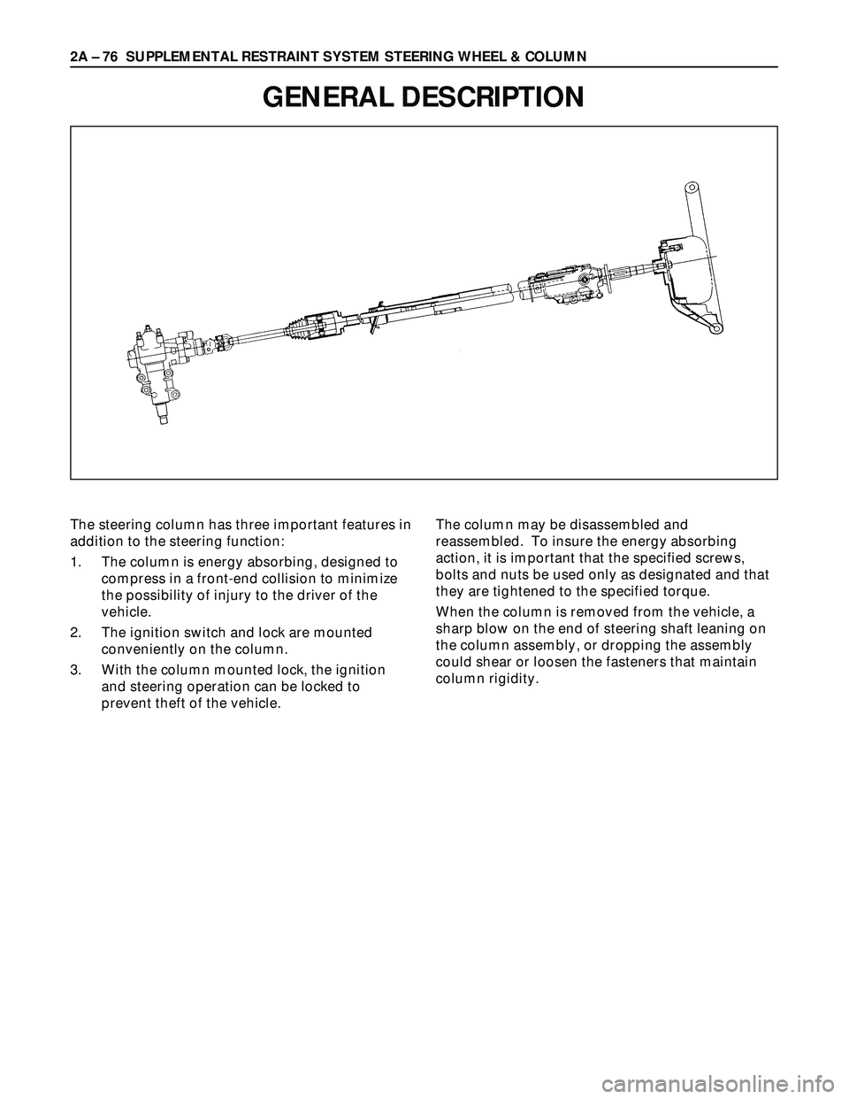
GENERAL DESCRIPTION
The steering column has three important features in
addition to the steering function:
1. The column is energy absorbing, designed to
compress in a front-end collision to minimize
the possibility of injury to the driver of the
vehicle.
2. The ignition switch and lock are mounted
conveniently on the column.
3. With the column mounted lock, the ignition
and steering operation can be locked to
prevent theft of the vehicle.The column may be disassembled and
reassembled. To insure the energy absorbing
action, it is important that the specified screws,
bolts and nuts be used only as designated and that
they are tightened to the specified torque.
When the column is removed from the vehicle, a
sharp blow on the end of steering shaft leaning on
the column assembly, or dropping the assembly
could shear or loosen the fasteners that maintain
column rigidity.
Page 438 of 3573
4A1±1 DIFFERENTIAL (FRONT)
DRIVELINE/AXLE
CONTENTS
Differential (Front) 4A1. . . . . . . . . . . . . . . . . . . . . . .
Differential (Rear/220mm) 4A2A. . . . . . . . . . . . . . . .
Differential (Rear/244mm) 4A2B. . . . . . . . . . . . . . . .
Driveline Control System (Shift on the Fly) 4B1. . Driveline Control System (TOD) 4B2. . . . . . . . . . .
Driveshaft System 4C. . . . . . . . . . . . . . . . . . . . . . .
Transfer Case (Standard Type) 4D1. . . . . . . . . . .
Transfer Case (TOD) 4D2. . . . . . . . . . . . . . . . . . . .
DIFFERENTIAL (FRONT)
CONTENTS
Service Precaution 4A1±1. . . . . . . . . . . . . . . . . . . . . .
Front Drive Axle 4A1±2. . . . . . . . . . . . . . . . . . . . . . . . .
Diagnosis 4A1±2. . . . . . . . . . . . . . . . . . . . . . . . . . . . .
Pinion Shaft Oil Seal 4A1±3. . . . . . . . . . . . . . . . . . . . .
Pinion Shaft Oil Seal and Associated Parts 4A1±3
Removal 4A1±3. . . . . . . . . . . . . . . . . . . . . . . . . . . . .
Inspection and Repair 4A1±4. . . . . . . . . . . . . . . . . .
Installation 4A1±4. . . . . . . . . . . . . . . . . . . . . . . . . . . .
Front Drive Axle Assembly 4A1±5. . . . . . . . . . . . . . .
Front Drive Axle Assembly and
Associated Parts 4A1±5. . . . . . . . . . . . . . . . . . . . . .
Removal 4A1±5. . . . . . . . . . . . . . . . . . . . . . . . . . . . . Installation 4A1±7. . . . . . . . . . . . . . . . . . . . . . . . . . . .
Differential Assembly 4A1±9. . . . . . . . . . . . . . . . . . . .
Disassembled View 4A1±9. . . . . . . . . . . . . . . . . . . .
Disassembly 4A1±9. . . . . . . . . . . . . . . . . . . . . . . . . .
Reassembly 4A1±12. . . . . . . . . . . . . . . . . . . . . . . . . .
Differential Cage Assembly 4A1±21. . . . . . . . . . . . . . .
Disassembled View 4A1±21. . . . . . . . . . . . . . . . . . . .
Disassembly 4A1±21. . . . . . . . . . . . . . . . . . . . . . . . . .
Inspection and Repair 4A1±22. . . . . . . . . . . . . . . . . .
Reassembly 4A1±23. . . . . . . . . . . . . . . . . . . . . . . . . .
Main Data and Specifications 4A1±25. . . . . . . . . . .
Special Tools 4A1±28. . . . . . . . . . . . . . . . . . . . . . . . . .
Service Precaution
WARNING: I F S O E Q U IPPED WITH A
SUPPLEMENTAL RESTRAINT SYSTEM (SRS),
REFER TO THE SRS COMPONENT AND WIRING
LOCATION VIEW IN ORDER TO DETERMINE
WHETHER YOU ARE PERFORMING SERVICE ON OR
NEAR THE SRS COMPONENTS OR THE SRS
WIRING. WHEN YOU ARE REFORMING SERVICE ON
OR NEAR THE SRS COMPONENTS OR THE SRS
WIRING, REFER TO THE SRS SERVICE
INFORMATION. FAILURE TO FOLLOW WARNINGS
COULD RESULT IN POSSIBLE AIR BAG
DEPLOYMENT, PERSONAL INJURY, OR
OTHERWISE UNNEEDED SRS SYSTEM REPAIRS.CAUTION: Always use the correct fastener in the
proper location. When you replace a fastener, use
ONLY the exact part number for that application.
ISUZU will call out those fasteners that require a
replacement after removal. ISUZU will also call out
the fasteners that require thread lockers or thread
sealant. UNLESS OTHERWISE SPECIFIED , do not
use supplemental coatings (Paints, greases, or other
corrosion inhibitors) on threaded fasteners or
fastener joint interfaces. Generally,such coatings
adversely affect the fastener torque and the joint
clamping force, and may damage the fastener. When
you install fasteners, use the correct tightening
sequence and specification. Following these
instructions can help you avoid damage to parts and
systems.
Page 439 of 3573
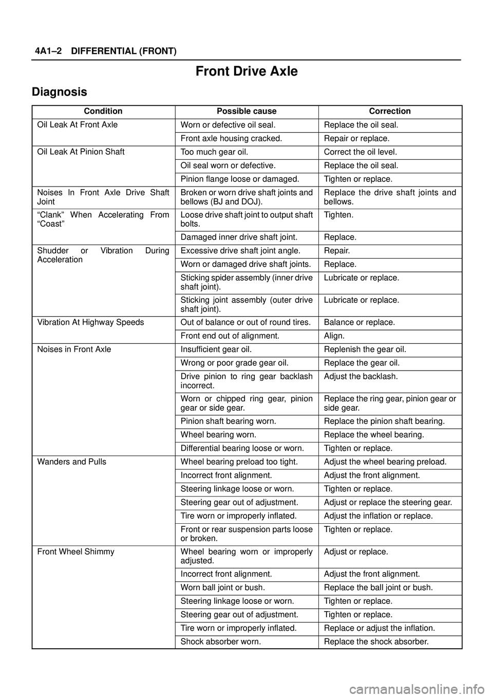
DIFFERENTIAL (FRONT) 4A1±2
Front Drive Axle
Diagnosis
ConditionPossible causeCorrection
Oil Leak At Front AxleWorn or defective oil seal.Replace the oil seal.
Front axle housing cracked.Repair or replace.
Oil Leak At Pinion ShaftToo much gear oil.Correct the oil level.
Oil seal worn or defective.Replace the oil seal.
Pinion flange loose or damaged.Tighten or replace.
Noises In Front Axle Drive Shaft
JointBroken or worn drive shaft joints and
bellows (BJ and DOJ).Replace the drive shaft joints and
bellows.
ªClankº When Accelerating From
ªCoastºLoose drive shaft joint to output shaft
bolts.Tighten.
Damaged inner drive shaft joint.Replace.
Shudder or Vibration During
Acceleration
Excessive drive shaft joint angle.Repair.
AccelerationWorn or damaged drive shaft joints.Replace.
Sticking spider assembly (inner drive
shaft joint).Lubricate or replace.
Sticking joint assembly (outer drive
shaft joint).Lubricate or replace.
Vibration At Highway SpeedsOut of balance or out of round tires.Balance or replace.
Front end out of alignment.Align.
Noises in Front AxleInsufficient gear oil.Replenish the gear oil.
Wrong or poor grade gear oil.Replace the gear oil.
Drive pinion to ring gear backlash
incorrect.Adjust the backlash.
Worn or chipped ring gear, pinion
gear or side gear.Replace the ring gear, pinion gear or
side gear.
Pinion shaft bearing worn.Replace the pinion shaft bearing.
Wheel bearing worn.Replace the wheel bearing.
Differential bearing loose or worn.Tighten or replace.
Wanders and PullsWheel bearing preload too tight.Adjust the wheel bearing preload.
Incorrect front alignment.Adjust the front alignment.
Steering linkage loose or worn.Tighten or replace.
Steering gear out of adjustment.Adjust or replace the steering gear.
Tire worn or improperly inflated.Adjust the inflation or replace.
Front or rear suspension parts loose
or broken.Tighten or replace.
Front Wheel ShimmyWheel bearing worn or improperly
adjusted.Adjust or replace.
Incorrect front alignment.Adjust the front alignment.
Worn ball joint or bush.Replace the ball joint or bush.
Steering linkage loose or worn.Tighten or replace.
Steering gear out of adjustment.Tighten or replace.
Tire worn or improperly inflated.Replace or adjust the inflation.
Shock absorber worn.Replace the shock absorber.
Page 441 of 3573
DIFFERENTIAL (FRONT) 4A1±4
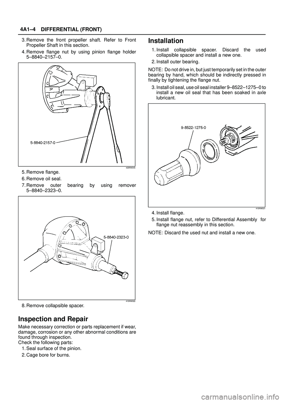
3. Remove the front propeller shaft. Refer to Front
Propeller Shaft in this section.
4. Remove flange nut by using pinion flange holder
5±8840±2157±0.
425RW045
5. Remove flange.
6. Remove oil seal.
7. Remove outer bearing by using remover
5±8840±2323±0.
415RW022
8. Remove collapsible spacer.
Inspection and Repair
Make necessary correction or parts replacement if wear,
damage, corrosion or any other abnormal conditions are
found through inspection.
Check the following parts:
1. Seal surface of the pinion.
2. Cage bore for burns.
Installation
1. Install collapsible spacer. Discard the used
collapsible spacer and install a new one.
2. Install outer bearing.
NOTE: Do not drive in, but just temporarily set in the outer
bearing by hand, which should be indirectly pressed in
finally by tightening the flange nut.
3. Install oil seal, use oil seal installer 9±8522±1275±0 to
install a new oil seal that has been soaked in axle
lubricant.
415RW021
4. Install flange.
5. Install flange nut, refer to Differential Assembly for
flange nut reassembly in this section.
NOTE: Discard the used nut and install a new one.