Front seat JAGUAR X308 1998 2.G Workshop Manual
[x] Cancel search | Manufacturer: JAGUAR, Model Year: 1998, Model line: X308, Model: JAGUAR X308 1998 2.GPages: 2490, PDF Size: 69.81 MB
Page 2361 of 2490

A pyrotechnic front seat belt pre-tensioning device with independent el ectronic sensing and retractor unit is installed at the
base of each 'B' post. In the event of se vere frontal impact, this provides additional front occupant protection by removing
any excess slack from the seat be lt. Seat belt pre-tensioning activates when a frontal impact of sufficient force occurs within
30 degrees of vehicle center line. Under such an impact, el ectronic sensors in the retractor unit fire, igniting the pre-
tensioner gas generator. The ga s generator initiates a chemical reaction, producing gases under pressure. Gas pressure
drives the piston/cable up a tube, rotating the retractor sp indle and removing excess slack from the seat belt. When the
pre-tensioner unit has been activated, the seat belt will lock and cannot be retracted or pulled from the reel.If a seat belt
pre-tensioner activates, a small quantity (less than 1 liter) of gas is produced containing nitrogen, oxygen and water vapor.
Page 2362 of 2490
Safety Belt System - Front Safety Belt Retractor
Removal and Installation
Removal
• WARNINGS:
IF A SEAT BELT PRETENSIONING UNIT IS INADVERTENTLY RUPTURED AND INGESTION AND/OR INHALATION
OCCURS, FIRST AID MUST BE APPLIED AND MEDICAL ADVICE SOUGHT.
NO ATTEMPT MUST BE MADE TO DISMANTLE A PRETENSIONING RETRACTOR UNIT. THERE ARE NO SERVICEABLE
PARTS.
WHEN HANDLING A RETRACTOR UNIT PISTON HOUSING, THE PISTON MUST ALWAYS BE POINTED DOWNWARDS
AND AWAY FROM ONE'S SELF AND OTHER PERSONNEL AND FINGERS MUST BE KEPT AWAY FOM THE TAKE-UP SPOOL
MECHANISM.
ANY PRETENSIONING UNIT DROPPED FROM A HEIGHT GREA TER THAN 0.3M (12 INCHES) MUST NOT BE FITTED TO A
VEHICLE.
UNACTIVATED PRE-TENSIONING UNIT COMPONENTS CONTAIN A SOLID, FLAMMABLE MATERIAL.
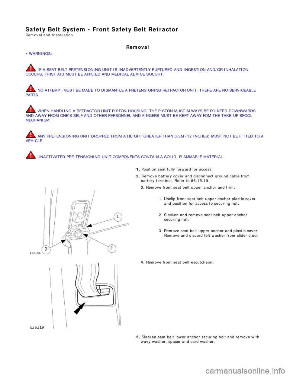
1. Position seat fully forward for access.
2. Remove battery cover and disc onnect ground cable from
battery terminal. Refer to 86.15.19.
3. Remove front seat belt upper anchor and trim.
1. Unclip front seat belt upper anchor plastic cover
and position for access to securing nut.
2. Slacken and remove se at belt upper anchor
securing nut.
3. Remove seat belt upper anchor and plastic cover. Remove and discard felt washer from slider stud.
4. Remove front seat belt escutcheon.
5. Slacken seat belt lower anchor securing bolt and remove with
wavy washer, spacer and card washer.
Page 2365 of 2490

Safety Belt System - Rear Safety Belt Retractor
Removal and Installation
Removal
1. Remove rear seat cushion. Refer to 76.70.37.
2. Remove rear headrests.
3. Slacken and remove bolt securi ng lower anchor to front of
inner wheel arch.
4. Slacken and remove bolt securing belt buckle cable to seat
pan and remove belt buckle assembly from vehicle.
5. Remove escutcheon.
1. Using a flat-bladed screwdriver in the two rectangular apertures, carefully withdraw
escutcheon from top of seat squab.
2. Remove escutcheon from belt via split in moulding.
6. Pass seat belt lower anchor plate and tongue through squab
aperture.
Page 2367 of 2490
Safety Belt System - Safety Belt Shoulder Height Adjuster
Removal and Installation
Removal
Installation
1.
Position front seat forward for access.
2. Remove battery cover and disconnect ground cable from battery
terminal. Refer to 86.15.19.
3. Remove seat belt upper anchor. Refer to 76.73.10
4. Remove 'B'post trim. Refer to 76.13.08.
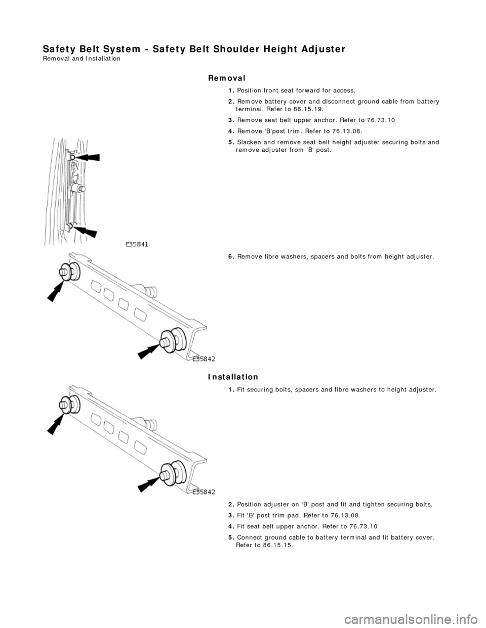
5. Slacken and remove seat belt heig ht adjuster securing bolts and
remove adjuster from 'B' post.
6. Remove fibre washers, spacers an d bolts from height adjuster.
1. Fit securing bolts, spacers and fi bre washers to height adjuster.
2. Position adjuster on 'B' post an d fit and tighten securing bolts.
3. Fit 'B' post trim pad. Refer to 76.13.08.
4. Fit seat belt upper an chor. Refer to 76.73.10
5. Connect ground cable to battery terminal and fit battery cover.
Refer to 86.15.15.
Page 2368 of 2490
Supplemental Restraint System -
Torques
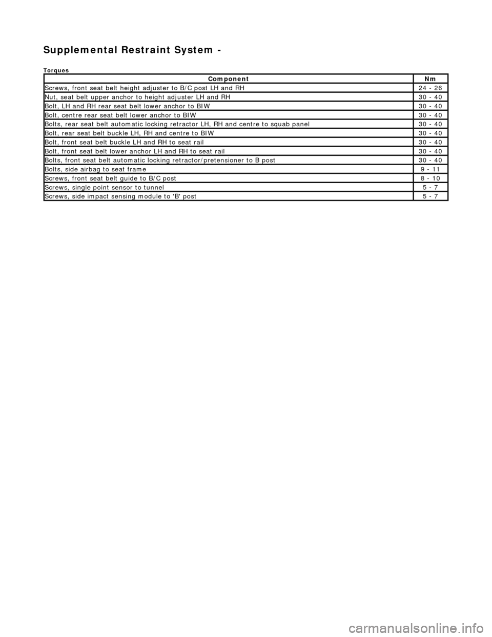
ComponentNm
Screws, front seat belt height adjuster to B/C post LH and RH24 - 26
Nut, seat belt upper anchor to height adjuster LH and RH30 - 40
Bolt, LH and RH rear seat belt lower anchor to BIW30 - 40
Bolt, centre rear seat belt lower anchor to BIW30 - 40
Bolts, rear seat belt automatic locking re tractor LH, RH and centre to squab panel30 - 40
Bolt, rear seat belt buckle LH, RH and centre to BIW30 - 40
Bolt, front seat belt buckle LH and RH to seat rail30 - 40
Bolt, front seat belt lower an chor LH and RH to seat rail30 - 40
Bolts, front seat belt automatic lock ing retractor/pretensioner to B post30 - 40
Bolts, side airbag to seat frame9 - 11
Screws, front seat belt guide to B/C post8 - 10
Screws, single point sensor to tunnel5 - 7
Screws, side impact sens ing module to 'B' post5 - 7
Page 2369 of 2490

Supplemental Restraint System - Air Bag Supplemental Restraint System
(SRS)
Description and Operation
Supplementary Restraint Air Bag System
Airbag/SRS units provided for driver and fro nt seat passemger protection, are installed in the center of the steering wheel,
the passenger side fascia and the oute r wing of each front seat. A single point sensing unit (SPS) mounted on the
transmission tunnel, below the ra dio, provides fully electronic impact sensing, control and diagnostics for the front airbags
Deployment of each side airbag is initia ted by a side impact sensing module (SISM) installed in the adjacent 'B' post. Each
SISM senses and electronically processes a crash pulse and if this exceeds the 'must fire' threshold, transmits a fire signal
to the SPS unit. The SPS unit monitors wh ole vehicle motion and on confirmation of a crash condition, transmits a firing
current pulse to the appropriate airbags. In the event of a side only impact, the SPS will send a current pulse to the airbag
on the struck only. Neither th e non-struck side airbag nor the frontal restraint system will be deployed under these
conditions. The airbag system can only be activated wh en the ignition switch is in position II or III.
Side Air Bags
Page 2370 of 2490
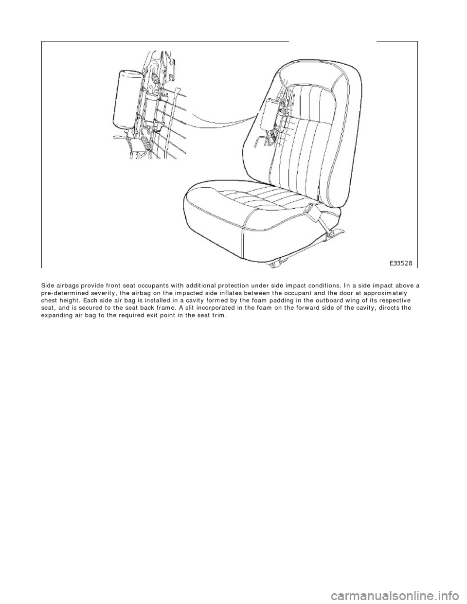
Side airbags provide front seat occupants with additional protection under side impa ct conditions. In a side impact above a
pre-determined severity, the ai rbag on the impacted side inflates between the occupant an d the door at approximately
chest height. Each side air bag is installe d in a cavity formed by the foam padding in the outboard wing of its respective
seat, and is secured to the seat back frame . A slit incorporated in the foam on the forward side of the cavity, directs the
expanding air bag to the required exit point in the seat trim.
Page 2386 of 2490
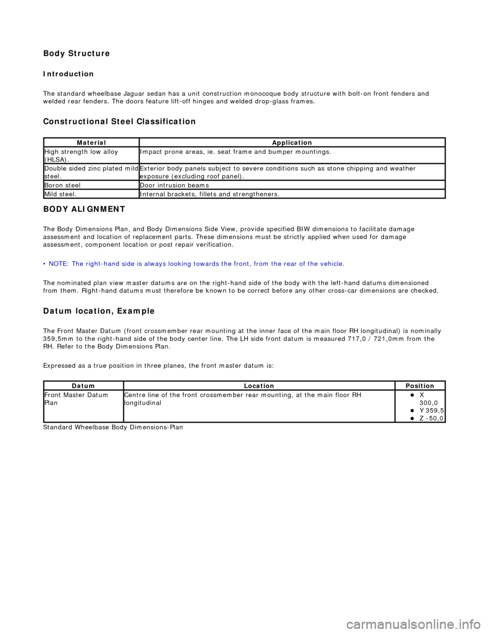
Body Structure
Introduction
The standard wheelbase Jaguar sedan has a unit construction monocoque body structure with bolt-on front fenders and
welded rear fenders. The doors feature lif t-off hinges and welded drop-glass frames.
Constructional Steel Classification
BODY ALIGNMENT
The Body Dimensions Plan, and Body Dimensions Side View, provide specified BIW dimensions to facilitate damage
assessment and location of replacemen t parts. These dimensions must be strictly applied when used for damage
assessment, component location or post repair verification.
• NOTE: The right-hand side is always looking towards the front, from the rear of the vehicle.
The nominated plan view master datums are on the right-hand side of the body with the left-hand datums dimensioned
from them. Right-hand datums must therefore be known to be correct before any other cross-car dimensions are checked.
Datum location, Example
The Front Master Datum (front crossmember rear mounting at the inner face of the main floor RH longitudinal) is nominally
359,5mm to the right-hand side of the body center line. The LH side fron t datum is measured 717,0 / 721,0mm from the
RH. Refer to the Body Dimensions Plan.
Expressed as a true posi tion in three planes, the front master datum is:
Standard Wheelbase Bo dy Dimensions-Plan
MaterialApplication
High strength low alloy
(HLSA).Impact prone areas, ie. seat frame and bumper mountings.
Double sided zinc plated mild steel.Exterior body panels subject to severe cond itions such as stone chipping and weather
exposure (excluding roof panel).
Boron steelDoor intrusion beams
Mild steel.Internal brackets, fill ets and strengtheners.
DatumLocationPosition
Front Master Datum
PlanCentre line of the front crossmember rear mounting, at the main floor RH
longitudinalX
300,0
Y 359,5 Z -50,0
Page 2417 of 2490
Panels centered between two adjacent panels must have equal gaps on either side. For exceptions to this, refer to the
appropriate specification. Gaps between ad jacent panels or components must not expose harnesses, labels, brackets or
visually poor joint or assembly conditions.
• NOTE: Sliding roof panel clearances are specified without the edge seal installed.
Areas of particular concern are, fuel filler flap, trunk lid to fenders and saddle panels, hood to fenders, grill and headlamps,
sliding roof to main roof panel, door gaps at fenders, B\C posts, roof drip rail an d rocker panel, and bumper cover to fenders
and cross car assemblies
Alignment
Panels must be correctly profiled to maintain cosmetic appearance, and ensure co rrect seating of seals with minimal wind
noise. Areas of particular concern are hood to fenders, trunk lid to fenders and saddle panels, doors to apertures, doors to
fenders and adjacent doors and relationship of the sliding roof panel leading and trailing edges to the main roof panel.
Exterior Fitments
Bezels, trims and lamps must be concentric with apertu res and have equal clearances with adjacent panels.
Areas of particular concern are headlamp to hood, fender and trim panel, exhaust tailpipe trim to bumper cover cut-out,
rear lamp assembly to trunk lid, fender and bumper cover trim, and side feature lines including body side mouldings, fender
to door and door to door.
Exterior Clearances and Alignments-Front
Page 2429 of 2490
Installation
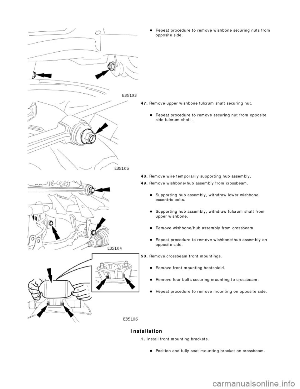
Repeat procedure to remove wishbone securing nuts from
opposite side.
47. Remove upper wishbone fu lcrum shaft securing nut.
Repeat procedure to remove securing nut from opposite
side fulcrum shaft .
48. Remove wire temporarily supporting hub assembly.
49. Remove wishbone/hub assembly from crossbeam.
Supporting hub assembly, wi thdraw lower wishbone
eccentric bolts.
Supporting hub assembly, wi thdraw fulcrum shaft from
upper wishbone.
Remove wishbone/hub assembly from crossbeam.
Repeat procedure to remove wishbone/hub assembly on
opposite side.
50. Remove crossbeam front mountings.
Remove front mounting heatshield.
Remove four bolts securing mounting to crossbeam.
Repeat procedure to remove mounting on opposite side.
1. Install front mounting brackets.
Position and fully seat mounting bracket on crossbeam.