JAGUAR X308 1998 2.G Workshop Manual
X308 1998 2.G
JAGUAR
JAGUAR
https://www.carmanualsonline.info/img/21/7640/w960_7640-0.png
JAGUAR X308 1998 2.G Workshop Manual
Page 2432 of 2490
10. With assistance position crossbeam/suspension assembly on
jack with protective wood under.
11. Traverse assembly into position below vehicle.
12. Ensure steering harn ess connector is positioned to avoid
damage during crossbeam lift .
13. NOTE: It may be necessary to use a hammer and drift to
finally align new mounting with body location.
Carefully raise crossbeam assembly into position.
Ensure that dowels of both crossbeam mountings are
correctly seated in body locations.
14. Ensure that both engine hydram ounts are correctly seated in
crossbeam locations.
15. Install crossbeam rear mountings.
Align rear mounting rubber with body location.
Install rear mounting securing bolt and nut and tighten
nut to 131-185 Nm.
Repeat procedure to install opposite side rear mounting
bolt and nut.
16. From engine compartment, install but do not tighten
crossbeam front RH bolts.
Page 2445 of 2490
correctly seated in body locations.
3. Ensure that both engine hydram ounts are correctly seated in
crossbeam locations.
4. From engine compartment, install but do not tighten
crossbeam front RH bolts.
5. From engine compartment, install crossbeam front LH bolts
and tighten to 22-28Nm.
6. Install power steering fluid reservoir.
Position reservoir on mounting bracket.
Install reservoir securi ng nuts and bolts.
Page 2456 of 2490
correctly seated in body locations.
3. Ensure that both engine hydram ounts are correctly seated in
crossbeam locations.
4. From engine compartment, install but do not tighten
crossbeam front RH bolts.
5. From engine compartment, install crossbeam front LH bolts
and tighten to 22-28Nm.
6. Install power steering fluid reservoir.
Position reservoir on mounting bracket.
Install reservoir securi ng nuts and bolts.
Page 2471 of 2490
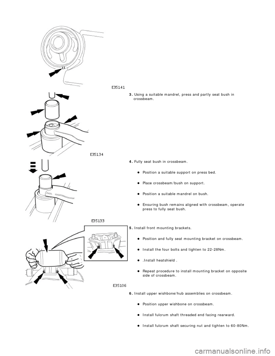
3. Using a suitable mandrel, pres s and partly seat bush in
crossbeam.
4. Fully seat bush in crossbeam.
Position a suitable support on press bed.
Place crossbeam/bush on support.
Position a suitable mandrel on bush.
Ensuring bush remains aligned with crossbeam, operate
press to fully seat bush.
5. Install front mounting brackets.
Position and fully seat mounting bracket on crossbeam.
Install the four bolts an d tighten to 22-28Nm.
.Install heatshield .
Repeat procedure to install mounting bracket on opposite
side of crossbeam.
6. Install upper wishbone/hub assemblies on crossbeam.
Position upper wishbone on crossbeam.
Install fulcrum shaft thread ed end facing rearward.
Install fulcrum shaft securing nut and tighten to 60-80Nm.
Page 2474 of 2490
Carefully raise crossbeam assembly into position.
Ensure that dowels of both crossbeam mountings seat
correctly in body locations.
18. Ensure that both engine hydramounts seat correctly in
crossbeam locations.
19. Install crossbeam rear mountings.
Align rear mounting rubber with body location.
Install rear mounting securing bolt and nut and tighten
nut to 131-185 Nm.
Repeat procedure to install opposite side rear mounting
securing bolt and nut.
20. From engine compartment, install but do not tighten
crossbeam front RH bolts.
21. From engine compartment, install crossbeam front LH bolts
and tighten to 22-28Nm.
Page 2477 of 2490
Remove blanking plugs from pinion housing ports.
Position pipes on pinion ports and seat 'O' rings.
31. Secure pipes to pinion housing.
Ensure pipes and retaining pl ate are correctly seated.
Install bolt and tighten to 9-12Nm.
32. Secure return pipe on steering rack.
1. Position pipe rubber support on steering rack.
2. Position pipe on support .
3. RHD vehicles. Position harness on pipe support rubber.
4. Secure pipe and harness to support with new tiestrap.
33. RHD vehicles. Using new tiestrap, secure harness to steering
rack.
34. Connect steering harness.
Route harness connector to body front location.
Connect steering ha rness connector.
Install connector in body retaining clip.


