check engine JAGUAR X308 1998 2.G Workshop Manual
[x] Cancel search | Manufacturer: JAGUAR, Model Year: 1998, Model line: X308, Model: JAGUAR X308 1998 2.GPages: 2490, PDF Size: 69.81 MB
Page 1405 of 2490

Pinpoint test C: P0702, P0753, P0758, P0763
Connect the scan tool 1
Have the DTC(s) and freeze frame data been recorded?
Yes GO to B2
B2: RENEW TORQUE CONVERTER
Renew the torque converter 1
Has the torque converter been renewed?
Yes GO to B3
B3: END
Drive the vehicle for a period from cold to include idle, brisk
acceleration and steady state cruising up to and including
normal engine temperature. Check for the presence of DTC 1
Has the fault code cleared?
Yes STOP
No Contact Jaguar Service
PINPOINT TEST C : P0702, P0753, P0758, P0763
TEST CONDITIONSDETAILS/RESULTS/ACTIONS
C1: RETRIEVE DTCS
• NOTE: Battery and or ECM disconnection prior to scanning wi ll erase all data, ensure that the correct DTC is present.
Connect the scan tool 1
Have the DTC(s) and freeze frame data been recorded?
Yes GO to C2
C2: CHECK HARNESS +VE CONTINUITY
Page 1412 of 2490
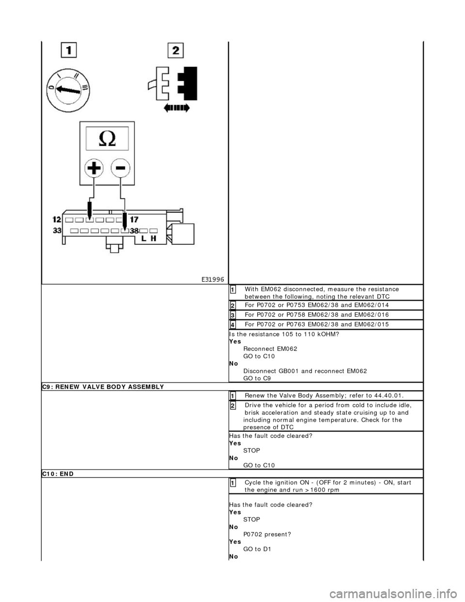
With EM062 disconnected, measure the resistance
between the following, noting the relevant DTC 1
For P0702 or P0753 EM062/38 and EM062/014 2
For P0702 or P0758 EM062/38 and EM062/016 3
For P0702 or P0763 EM062/38 and EM062/015 4
Is the resistance 105 to 110 kOHM?
Yes Reconnect EM062
GO to C10
No Disconnect GB001 and reconnect EM062
GO to C9
C9: RENEW VALVE BODY ASSEMBLY
Renew the Valve Body Assembly; refer to 44.40.01. 1
Drive the vehicle for a period from cold to include idle,
brisk acceleration and steady state cruising up to and
including normal engine temperature. Check for the
presence of DTC 2
Has the fault code cleared?
Yes STOP
No GO to C10
C10: END
Cycle the ignition ON - (OFF for 2 minutes) - ON, start
the engine and run >1600 rpm 1
Has the fault code cleared?
Yes STOP
No P0702 present?
Yes GO to D1
No
Page 1427 of 2490

Pinpoint test H: P0730, P0780
Connect the scan tool 1
Have the DTC(s) and freeze frame data been recorded?
Yes GO to G2
G2: RENEW TCM
Renew the TCM 1
Has the TCM been renewed?
Yes GO to G3
G3: END
• NOTE: The following step must be carried out in order that sy stem adaptions can take place.
Drive the vehicle for a period from cold to include idle, brisk
acceleration and steady state cruising up to and including
normal engine temperature. Check for the presence of DTC 1
Has the fault code cleared?
Yes STOP
No Contact Jaguar Service
PINPOINT TEST H : P0730, P0780
TEST CONDITIONSDETAILS/RESULTS/ACTIONS
H1: RETRIEVE DTCS
• NOTE: Battery and or ECM disconnection prior to scanning wi ll erase all data, ensure that the correct DTC is present.
Connect the scan tool 1
Have the DTC(s) and freeze frame data been recorded?
Yes GO to H2
H2: RENEW VALVE BODY ASSEMBLY
Renew the valve body assembly 1
Drive the vehicle for a period from cold to include idle, brisk
acceleration and steady state cruising up to and including
normal engine temperature. Check for the presence of DTC 2
Has the fault code cleared?
Page 1431 of 2490
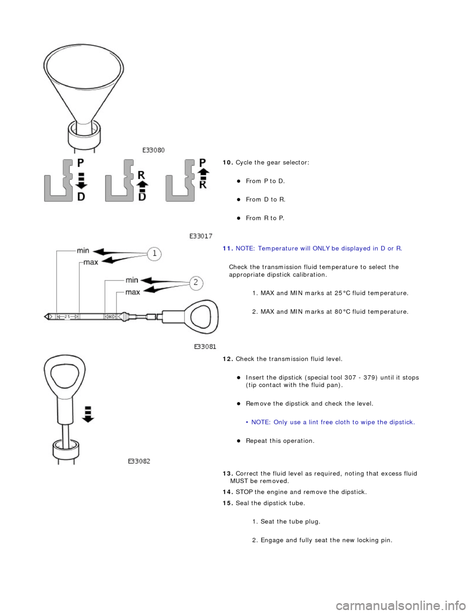
10. Cycle the gear selector:
From P to D.
From D to R.
From R to P.
11. NOTE: Temperature will ONLY be displayed in D or R.
Check the transmission fluid temperature to select the
appropriate dipstick calibration. 1. MAX and MIN marks at 25°C fluid temperature.
2. MAX and MIN marks at 80°C fluid temperature.
12. Check the transmission fluid level.
Insert the dipstick (special tool 307 - 379) until it stops
(tip contact with the fluid pan).
Remove the dipstick an d check the level.
• NOTE: Only use a lint free cloth to wipe the dipstick.
Repeat this operation.
13. Correct the fluid leve l as required, noting that excess fluid
MUST be removed.
14. STOP the engine and remove the dipstick.
15. Seal the dipstick tube.
1. Seat the tube plug.
2. Engage and fully seat the new locking pin.
Page 1504 of 2490

Automatic Transmission/Transaxle External Controls - 4.0L SC V8 - AJ26 -
External Controls
Diagnosis and Testing
Problem Solving - Transmission Shift
Quick Reference Fault Chart
Special Tool(s)
Digital multimeter
Generic scan tool
SymptomPossible SourcesAction
Shift stuck in P Selector cable seized
*GO to 44.15.08
*
Interlock solenoid not operating
*GO to PDU
*
Interlock latch seized
Transmission faulty
*
*Mechanical check
*
Operator sequence error
*Correct the sequence
*
Vehicle rolls on P Incorrect cable adjustment
*GO 44.15.07
*
Faulty parking pawl (transmission internal)
*Mechanical check
*
R does not engageIncorrect cable adjustment
*GO to 44.15.07
*
Transmission fluid level incorrect
*GO to 44.24.02
*
N not achievedIncorrect cable adjustment
Transmission faulty
*
*GO to 44.15.07
*
D does not engageIncorrect cable adjustment *GO to 44.15.07
*
Transmission fluid level incorrect
*GO to 44.24.02
*
Transmission faulty
*Mechanical check
*
Lower ratios will not holdExcessive engine temperature
DLS fault
*
*GO to PDU
*
Shift lever position not visually correctIncorrect DLS adjustment
*GO to 44.15.07
*
Shift lever has no effect upon the
transmission and resistance cannot be
feltCable disconnected or broken
Transmission selector problem
Shift lever drive pin adrift
*
*
*Mechanical check
*
Shift lever position not align correctly
following manual selection of lower
ratiosSliding block drive pin displaced - following road debris contact
*Mechanical check. Renew the selector if
damaged, or re-align the drive pin and
sliding block
*
Shift lever detent indistinct in 3
causing poor locationDLS detent fault
*GO to Renew the DLS
*
Shift may be moved from P without
brake pedal operationInterlock latch fault
*Mechanical check
*
Solenoid permanently activated
*GO to PDU
*
Engine may be started in positions
other than P or N Incorrect cable adjustment
DLS fault
*
*GO to 44.15.07
*
Shift lever vibrationLoose selector assembly
Cable isolation fault
*
*Mechanical check
*
Noise / rattle from 'J' gateDebris in the mechanism
*Clean
*
Worn 'J' gate track gasket
allowing lever and moulding to
contact
*GO to 44.15.05
*
Page 1520 of 2490

moving the set position of either the gear selector lever or the selector lever on the transmission casing.
3. Tighten to 22-28 Nm.
4. Verify the 'N' setting.
6. Check that all released connec tors are safely insulated and
connect the vehicle battery.
7. Switch ON the ignition.
8. Adjust the position of the linear switch so that the selector 'N'
position graphic illuminates. Ti ghten the four screws to 0,7-1
Nm.
9. Move the gear selector to 'R' to confirm that the 'R' position
graphic illuminates.
10. Check that the engine will start when the gear selector is in
the 'N' and 'P' positions, bu t not in any other position.
11. Move the gear selector to 'N'.
12. Switch OFF the ignition.
13. Disconnect the battery.
14. Install the console assembly, operation 76.25.01.
15. Install the console finisher veneer panel, operation 76.47.26.
16. Install the J-gate surround, operation 76.25.24.
17. Perform the Battery Reconnection Procedure described in
Operation 86.15.15.
Page 1531 of 2490
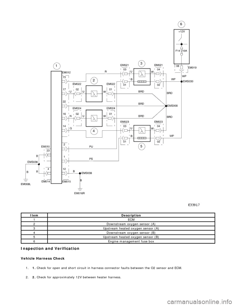
Inspection and Verification
Vehicle Harness Check
1.1. Check for open and short circuit in harness conn ector faults between the O2 sensor and ECM.
2. 2. Check for approximately 12V between heater harness.
ItemDescription
1ECM
2Downstream oxygen sensor (A)
3Upstream heated oxygen sensor (A)
4Downstream oxygen sensor (B)
5Upstream heated oxygen sensor (B)
6Engine management fuse box
Page 1532 of 2490

Heater Resistance Check
1.1. Verify that the resistance between the heater term inals is between 4OHM and 10OHM at -20°C to 100°C.
Performance Check
1.1. Run the engine at 2500 RPM for two minutes, to heat up the O2 sensor.
2. 2. Check the voltage of the sensor output: Alternates between less than 0.4V at feed back engine conditions and in
excess of 0.5V, see graph.
These voltages are for reference only.
3. 3. Check that cycle of the upstream se nsor output is in accordance with the appropriate pinpoint test.
4. 4. Check that cycle of the downstream sensor output is in accordance with the appropriate pinpoint test.
Page 1535 of 2490
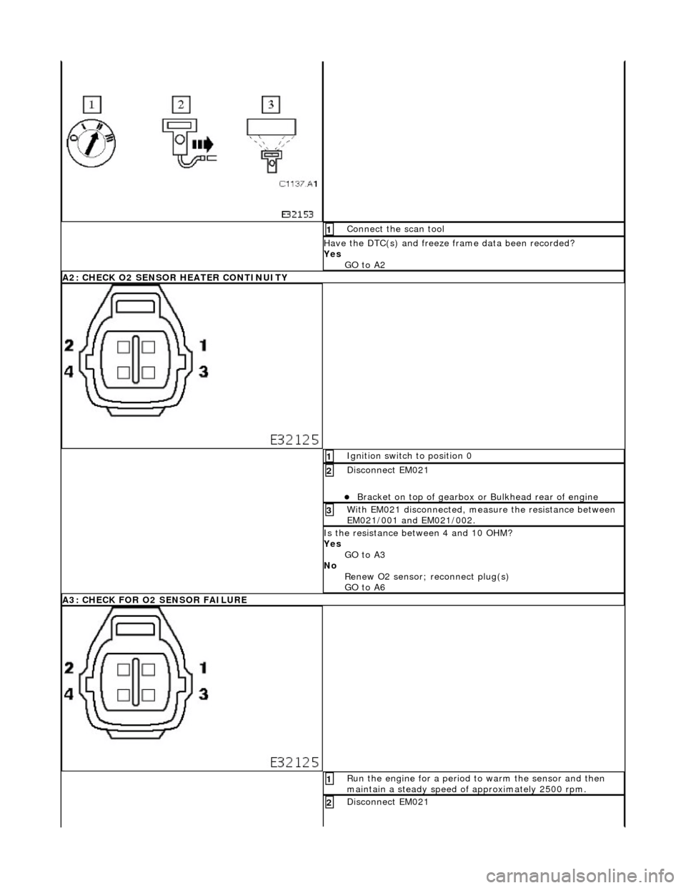
Connect the scan tool 1
Have the DTC(s) and freeze frame data been recorded?
Yes GO to A2
A2: CHECK O2 SENSOR HEATER CONTINUITY
Ignition switch to position 0 1
Disconnect EM021
Bracket on top of gearbox or Bulkhead rear of engine
2
With EM021 disconnected, measure the resistance between
EM021/001 and EM021/002. 3
Is the resistance between 4 and 10 OHM?
Yes
GO to A3
No Renew O2 sensor; reconnect plug(s)
GO to A6
A3: CHECK FOR O2 SENSOR FAILURE
Run the engine for a period to warm the sensor and then
maintain a steady speed of approximately 2500 rpm. 1
Disconnect EM021 2
Page 1536 of 2490
Bracket on top of gearbox or Bulkhead rear of engine
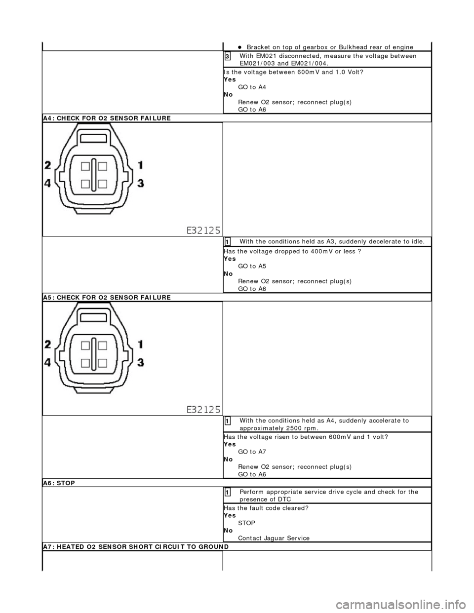
With EM021 disconnected, measure the voltage between
EM021/003 and EM021/004. 3
Is the voltage between 600mV and 1.0 Volt?
Yes
GO to A4
No Renew O2 sensor; reconnect plug(s)
GO to A6
A4: CHECK FOR O2 SENSOR FAILURE
With the conditions held as A3, suddenly decelerate to idle. 1
Has the voltage dropped to 400mV or less ?
Yes GO to A5
No Renew O2 sensor; reconnect plug(s)
GO to A6
A5: CHECK FOR O2 SENSOR FAILURE
With the conditions held as A4, suddenly accelerate to
approximately 2500 rpm. 1
Has the voltage risen to between 600mV and 1 volt?
Yes GO to A7
No Renew O2 sensor; reconnect plug(s)
GO to A6
A6: STOP
Perform appropriate service drive cycle and check for the
presence of DTC 1
Has the fault code cleared?
Yes STOP
No Contact Jaguar Service
A7: HEATED O2 SENSOR SHORT CIRCUIT TO GROUND