sensor JAGUAR X308 1998 2.G Workshop Manual
[x] Cancel search | Manufacturer: JAGUAR, Model Year: 1998, Model line: X308, Model: JAGUAR X308 1998 2.GPages: 2490, PDF Size: 69.81 MB
Page 1063 of 2490
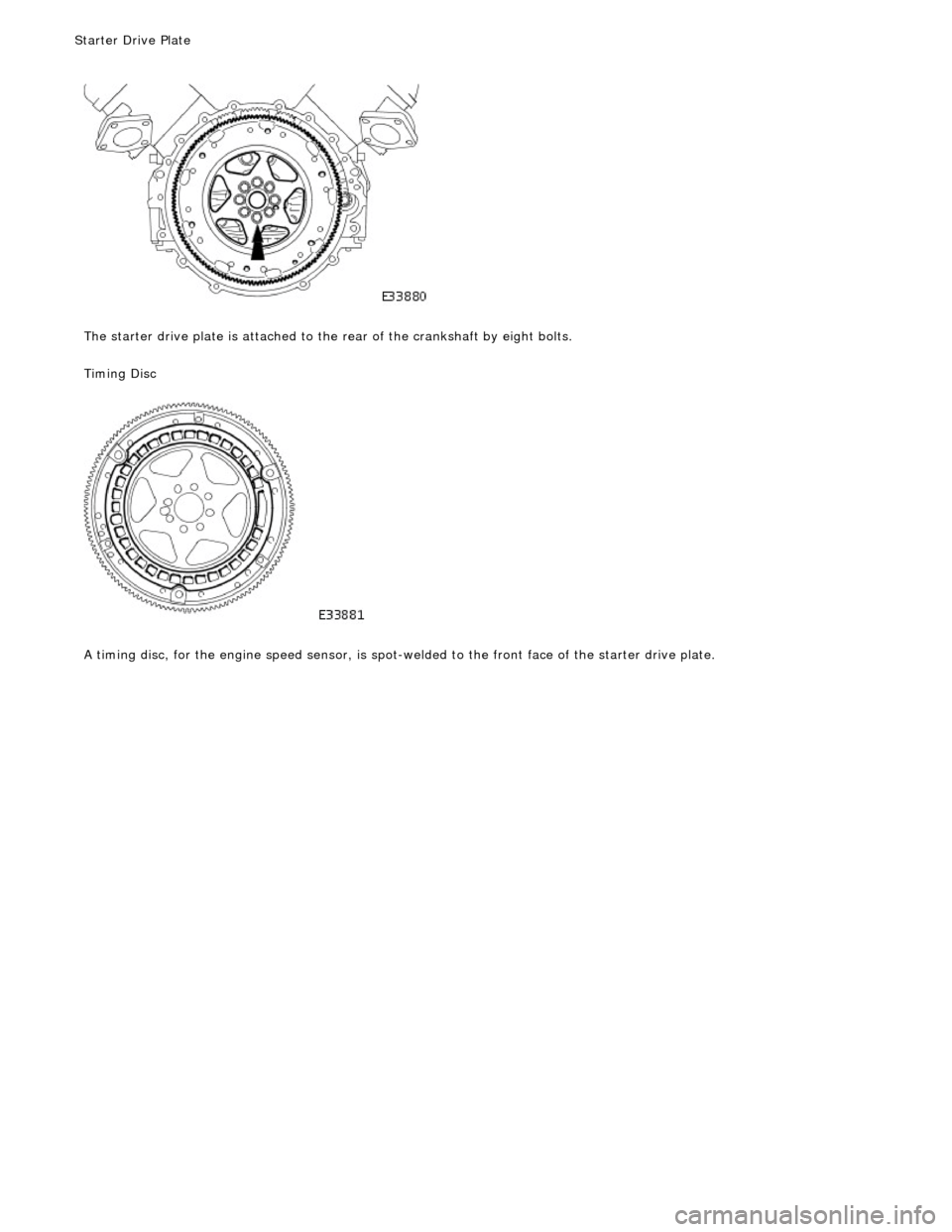
Th
e starter drive plate is attached to the rear of the crankshaft by eight bolts.
Timing Disc
A timing disc, for the engine speed sensor, is spot-w elded to the front face of the starter drive plate.
Starter Drive Plate
Page 1073 of 2490

Engine Igni
tion -
Engine Ignition
Description an
d Operation
I
gnition coil and spark plug reference
Any positional r
eferences are base
d upon the following convention:
viewing from the driving position, the right-hand cylinder bank is designated bank 1 (A on circuit diagrams) and the left-
hand cylinder bank as bank 2 (B on circuit diagrams).
The cylinder bores of each bank are number ed 1 to 4, from the front of the vehicle.
Ig
nition System
Th
e ignition system provides timing cont
rol in accordance with the engine mana gement strategy and powertrain sensor
inputs; the system consists of:
engine
control module
igni
tion coils supply relay
ignit
ion control modules
igni
tion coils
spark plu
gs
Engine Control Module (ECM)
pr
ovides triggering for the ignition control modules
to control individual firing of the spark plugs
supplies ground for
the igni
tion coils supply relay
I
gnition Coils Supply Relay
The
ignition coils supply relay is located
in the engine and transmission control mo dule compartment; refer to Relay Details
in Electrical Wiring and Circuit Protection, Section 418-01.
The ECM switches a ground to the coil of the ignition coils supply relay; the relay energizes and switches a 12v supply to the
ignition control modules and the ignition coils.
I
gnition Control Modules
Page 1078 of 2490
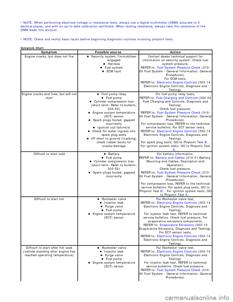
• NO
TE: When performing electrical voltag
e or resistance tests, always use a digital multimeter (DMM) accurate to 3
decimal places, and with an up-t o-date calibration certificate. When testing resistance, always take the resistance of the
DMM leads into account.
• NOTE: Check and rectify basic faults before beginning diagnostic ro utines involving pinpoint tests.
Sym
ptom Chart
Sy
m
ptom
Possib
l
e source
Acti
o
n
Engine
cranks, but does
not fire
Secu
rit
y system /Immobiliser
engaged
Harness Fue l
system
ECM fault
Contact deal er techni
cal support for
information on security system. Check fuel
system pressure,
REFER to: Fuel System Pressure Check
(310
-
00 Fuel System - Genera l Information, General
Procedures).
For ECM tests,
REFER to: Electronic Engine Controls
(303
-14
Electronic Engine Co ntrols, Diagnosis and
Testing).
Engine cranks and
fi
res, but will not
start
Fu
el pump relay
Fuel
pump
Cyl
i
nder compression loss
(short-term. Refer to bulletin; 303-52)
Engine coolan t
temperature
(ECT) sensor
Spark plugs fouled, gapp
ed
incorrectly
Ignition coil fail
ure(s)
Check f
o
r water ingress into
spark plug wells
HT sho rt to ground (tracking)
check rubber
boots for
cracks/damage
Fo
r fuel pump relay tests,
REFER to: Fuel Charging and Controls
(303
-04
Fuel Charging and Controls, Diagnosis and Testing).
Check fuel pressure,
REFER to: Fuel System Pressure Check
(310
-
00 Fuel System - Genera l Information, General
Procedures).
For compression loss, REFER to the technical service bulletins. For ECT sensor tests,
REFER to: Electronic Engine Controls
(303
-14
Electronic Engine Co ntrols, Diagnosis and
Testing).
For spark plug tests, GO to Pinpoint Test B.
.
For ign i
tion system tests, GO to Pinpoint Test
A.
.
Diff
icult to start cold
Batt
ery Fuel
pump
Cyl
i
nder compression loss
(short-term. Refer to bulletin; 303-52)
Spark plugs fouled, gapp
ed
incorrectly
F o
r battery information,
REFER to: Battery and Cables
(414
-01 Battery,
Mounting and Cables, Description and Operation).
Check fuel pressure.
REFER to: Fuel System Pressure Check
(310
-
00 Fuel System - Genera l Information, General
Procedures).
For compression loss, REFER to the technical service bulletins. For spark plug tests, GO to
Pinpoint Test B.
. For ig
nition system tests, GO
to Pinpoint Test A.
.
Diff
icult to start hot
Roc
h
ester valve
Injec
t
or leak
Purge
val
ve
Fue
l
pump
Engine coolan
t
temperature
(ECT) sensor
F or R
ochester
valve test,
REFER to: Electronic Engine Controls
(303
-14
Electronic Engine Co ntrols, Diagnosis and
Testing).
For injector leak test, REFER to technical
service bulletins. Check fuel pressure. For evaporative emissions components,
REFER to: Evaporative Emissions
(303
-13
Evaporative Emissions, Diagnosis and Testing).
For ECT sensor tests,
REFER to: Electronic Engine Controls
(303
-14
Electronic Engine Co ntrols, Diagnosis and
Testing).
D iff
icult to start after hot soak
(vehicle standing after engine has reached operating temperature)
Roc h
ester valve
Injec
t
or leak
Purge
val
ve
Fue
l
pump
Engine coolan
t
temperature
(ECT) sensor
F or R
ochester
valve test,
REFER to: Electronic Engine Controls
(303
-14
Electronic Engine Co ntrols, Diagnosis and
Testing).
For injector leak test, REFER to technical service bulletins. Check fuel pressure,
REFER to: Fuel System Pressure Check
(310
-
00 Fuel System - Genera l Information, General
Procedures).
Page 1079 of 2490
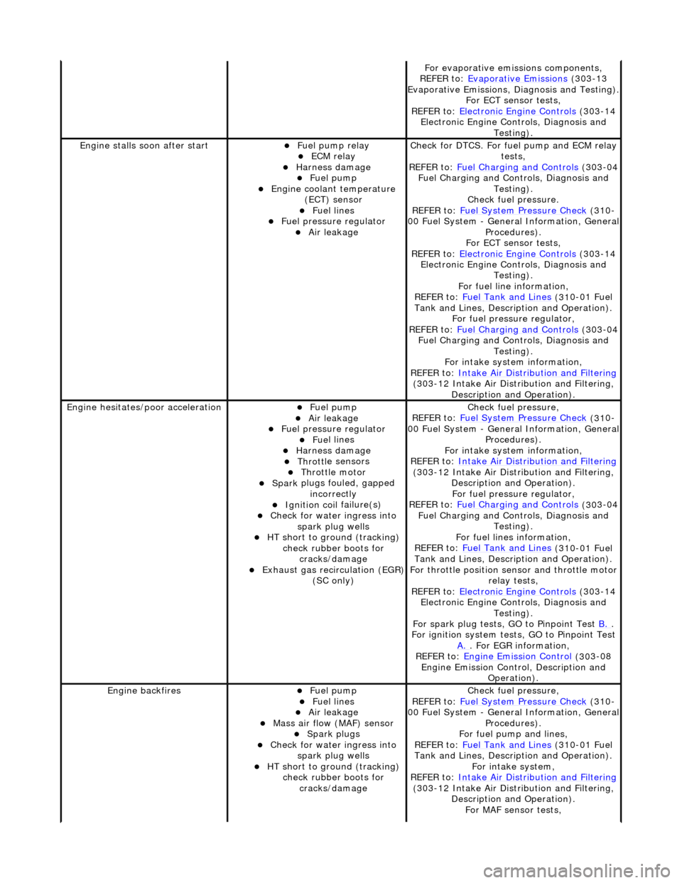
F
or evaporative emissions components,
REFER to: Evaporative Emissions
(30
3-13
Evaporative Emissions, Diagnosis and Testing).
For ECT sensor tests,
REFER to: Electronic Engine Controls
(30
3-14
Electronic Engine Co ntrols, Diagnosis and
Testing).
Engine stalls
soon after start
F
uel pump relay
ECM relay
Harness damage Fue
l pump
Engine coolan
t temperature
(ECT) sensor
Fue
l lines
F
uel pressure regulator
Air leakage
Check f
or DTCS. For fuel pump and ECM relay
tests,
REFER to: Fuel Charging and Controls
(30
3-04
Fuel Charging and Controls, Diagnosis and Testing).
Check fuel pressure.
REFER to: Fuel System Pressure Check
(31
0-
00 Fuel System - Genera l Information, General
Procedures).
For ECT sensor tests,
REFER to: Electronic Engine Controls
(30
3-14
Electronic Engine Co ntrols, Diagnosis and
Testing).
For fuel line information,
REFER to: Fuel Tank and Lines
(31
0-01 Fuel
Tank and Lines, Description and Operation).
For fuel pressure regulator,
REFER to: Fuel Charging and Controls
(30
3-04
Fuel Charging and Controls, Diagnosis and Testing).
For intake system information,
REFER to: Intake Air Distribution and Filtering
(30
3-12 Intake Air Distribution and Filtering,
Description and Operation).
Engine hesi
tates/poor acceleration
Fue
l pump
Air leakage
F
uel pressure regulator
Fue
l lines
Harness damage Throttl
e sensors
Throttl
e motor
Spark
plugs fouled, gapped
incorrectly
Ignition coil
failure(s)
Check f
or water ingress into
spark plug wells
HT sho
rt to ground (tracking)
check rubber boots for cracks/damage
Exhaus
t gas recirculation (EGR)
(SC only)
Chec
k fuel pressure,
REFER to: Fuel System Pressure Check
(31
0-
00 Fuel System - Genera l Information, General
Procedures).
For intake system information,
REFER to: Intake Air Distribution and Filtering
(30
3-12 Intake Air Distribution and Filtering,
Description and Operation). For fuel pressure regulator,
REFER to: Fuel Charging and Controls
(30
3-04
Fuel Charging and Controls, Diagnosis and Testing).
For fuel lines information,
REFER to: Fuel Tank and Lines
(31
0-01 Fuel
Tank and Lines, Description and Operation).
For throttle position se nsor and throttle motor
relay tests,
REFER to: Electronic Engine Controls
(30
3-14
Electronic Engine Co ntrols, Diagnosis and
Testing).
For spark plug tests, GO to Pinpoint Test B.
.
For ign
ition system tests, GO to Pinpoint Test
A.
. F
or EGR information,
REFER to: Engine Emission Control
(30
3-08
Engine Emission Cont rol, Description and
Operation).
Engine ba
ckfires
Fue
l pump
Fue
l lines
Air leakage
Mass ai
r flow (MAF) sensor
Spark plugs
Check f
or water ingress into
spark plug wells
HT sho
rt to ground (tracking)
check rubber boots for cracks/damage
Chec
k fuel pressure,
REFER to: Fuel System Pressure Check
(31
0-
00 Fuel System - Genera l Information, General
Procedures).
For fuel pump and lines,
REFER to: Fuel Tank and Lines
(31
0-01 Fuel
Tank and Lines, Description and Operation).
For intake system,
REFER to: Intake Air Distribution and Filtering
(30
3-12 Intake Air Distribution and Filtering,
Description and Operation). For MAF sensor tests,
Page 1080 of 2490
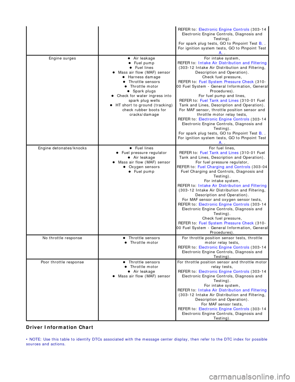
Driver Information
Chart
•
NOTE: Use this table to identify DTCs associated with the me
ssage center display, then refer to the DTC index for possible
sources and actions.
REF E
R to:
Electronic Engine Controls
(303
-14
Electronic Engine Co ntrols, Diagnosis and
Testing).
For spark plug tests, GO to Pinpoint Test B.
.
For ign i
tion system tests, GO to Pinpoint Test
A.
.
Engine s
urges
Air leakage
Fue
l
pump
Fue
l
lines
Mass ai
r fl
ow (MAF) sensor
Harness damage Throttl
e
sensors
Throttl
e
motor
Spark plugs
Check fo
r water ingress into
spark plug wells
HT short to ground (tracking) check rubber
boots for
cracks/damage
Fo r
intake system,
REFER to: Intake Air Distribution and Filtering
(30 3
-12 Intake Air Distribution and Filtering,
Description and Operation). Check fuel pressure,
REFER to: Fuel System Pressure Check
(310
-
00 Fuel System - Genera l Information, General
Procedures).
For fuel pump and lines,
REFER to: Fuel Tank and Lines
(310
-01 Fuel
Tank and Lines, Description and Operation).
For MAF sensor, throttle position sensor and
throttle motor relay tests,
REFER to: Electronic Engine Controls
(303
-14
Electronic Engine Co ntrols, Diagnosis and
Testing).
For spark plug tests, GO to Pinpoint Test B.
.
For ign i
tion system tests, GO to Pinpoint Test
A.
.
Engine detonates/k
nocks
Fue
l
lines
F
u
el pressure regulator
Air leakage
Mass air fl
ow (MAF) sensor
O
xygen senso
rs
Fue
l
pump
F
o
r fuel lines,
REFER to: Fuel Tank and Lines
(310
-01 Fuel
Tank and Lines, Description and Operation).
For fuel pressure regulator,
REFER to: Fuel Charging and Controls
(303
-04
Fuel Charging and Controls, Diagnosis and Testing).
For intake system,
REFER to: Intake Air Distribution and Filtering
(30 3
-12 Intake Air Distribution and Filtering,
Description and Operation).
For MAF sensor and oxyg en sensor tests,
REFER to: Electronic Engine Controls
(303
-14
Electronic Engine Co ntrols, Diagnosis and
Testing).
Check fuel pressure,
REFER to: Fuel System Pressure Check
(310
-
00 Fuel System - Genera l Information, General
Procedures).
No t
hrottle response
Throttl
e
sensors
Throttl
e
motor
Fo
r th
rottle position sensor tests, throttle
motor relay tests,
REFER to: Electronic Engine Controls
(303
-14
Electronic Engine Co ntrols, Diagnosis and
Testing).
Poor throttle responseThrottl e
sensors
Throttl
e
motor
Air leakage Mass air fl
ow (MAF) sensor
F
or throttl
e position se
nsor and throttle motor
relay tests,
REFER to: Electronic Engine Controls
(303
-14
Electronic Engine Co ntrols, Diagnosis and
Testing).
For intake system,
REFER to: Intake Air Distribution and Filtering
(30 3
-12 Intake Air Distribution and Filtering,
Description and Operation). For MAF sensor tests,
REFER to: Electronic Engine Controls
(303
-14
Electronic Engine Co ntrols, Diagnosis and
Testing).
Page 1095 of 2490
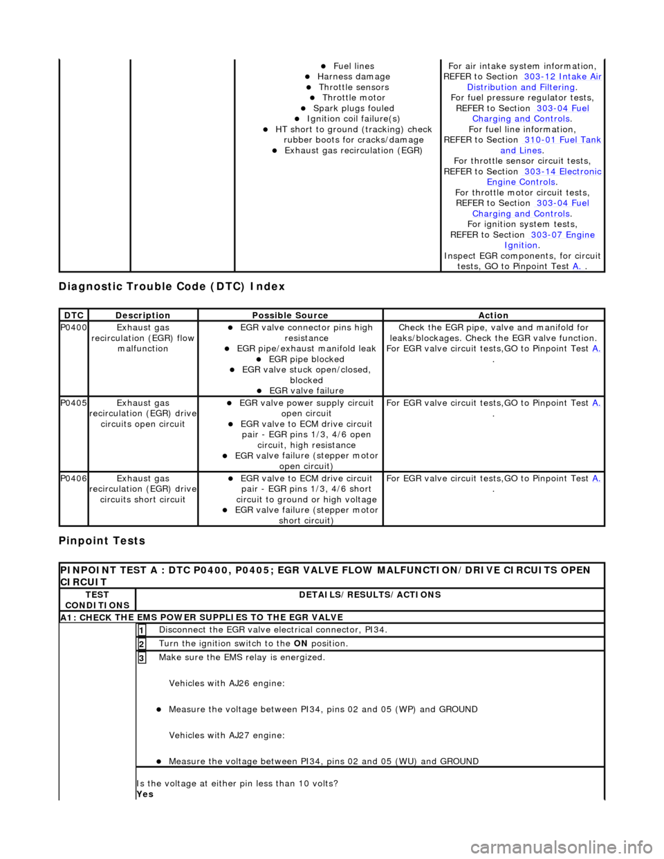
Diagnostic Trouble Code (D
TC) Index
Pinpoint Tests
Fue
l lines
Harness damage
Throttl
e sensors
Throttl
e motor
Spark plugs
fouled
Ignition coil
failure(s)
HT sho
rt to ground (tracking) check
rubber boots for cracks/damage
Exhaus
t gas recirculation (EGR)
F
or air intake syst
em information,
REFER to Section 303
-12
Intake Air
Distribu
tion and Filtering
.
F
or fuel pressure
regulator tests,
REF
ER to Section 303
-04
Fuel
Charging and Con
trols
.
F
or fuel line information,
REFER to Section 310
-01
Fuel Tank
and Lines.
F
or throttle sensor
circuit tests,
REFER to Section 303
-14
Electronic
Engine
Controls
.
Fo
r throttle motor
circuit tests,
REFER to Section 303
-04
Fuel
Charging and Con
trols
.
For ign
ition system tests,
REFER to Section 303
-07
Engine
Ignition.
Inspe
ct EGR components, for circuit
tests, GO to Pinpoint Test A.
.
DT
C
De
scription
Possib
le Source
Acti
on
P0400Exhaus
t gas
recirculation (EGR) flow malfunction
EGR
valve connector pins high
resistance
EGR pipe/exhaust manifold leak EGR pipe block
ed
EGR val
ve stuck open/closed,
blocked
EGR
valve failure
Check the EGR pi
pe, valve and manifold for
leaks/blockages. Check the EGR valve function.
For EGR valve circuit tests,GO to Pinpoint Test A.
.
P0405Exhaus
t gas
recirculation (EGR) drive
circuits open circuit
EGR valve power supply circuit o
pen circuit
EGR valve t
o ECM drive circuit
pair - EGR pins 1/3, 4/6 open circuit, high resistance
EGR val
ve failure (stepper motor
open circuit)
F
or EGR valve circuit tests,GO to Pinpoint Test
A.
.
P0406Exhaus
t gas
recirculation (EGR) drive
circuits short circuit
EGR valve t
o ECM drive circuit
pair - EGR pins 1/3, 4/6 short
circuit to ground or high voltage
EGR val
ve failure (stepper motor
short circuit)
F
or EGR valve circuit tests,GO to Pinpoint Test
A.
.
P
INPOINT TEST A : DTC P0400, P0405; EGR VALV
E FLOW MALFUNCTION/DRIVE CIRCUITS OPEN
CIRCUIT
TE
ST
CONDITIONS
D
ETAILS/RESULTS/ACTIONS
A1: CHECK
THE EMS POWER SU
PPLIES TO THE EGR VALVE
D
isconnect the EGR valve electrical connector, PI34.
1
Turn the ignition swi
tch to the ON
position.
2
Make sure the EMS re lay i
s energized.
Vehicles with AJ26 engine:
Me
asure the voltage between PI34, pins 02 and 05 (WP) and GROUND
Vehicles with AJ27 engine:
Me
asure the voltage between PI34, pins 02 and 05 (WU) and GROUND
3
Is th
e voltage at either pin less than 10 volts?
Yes
Page 1107 of 2490

Intake Air Distribution and Filtering - Intake Air Distribution and Filtering
Description an
d Operation
I
ntake Air Distribution and Filtering - Normally Aspirated Vehicles
Air Intake Asse
mbly
The air cleaner assembly consists of a two piece box containing the air filter, an airflow/temperature unit and the air intake
duct which connects to the top of the throttle assembly. The en gine full load breather feeds into the intake duct from the
bank 1 camshaft cover. A tuned stub on the ai r intake duct reduces the intake noise level.
Mass Air Flow and Temperature Sensors
The intake air is monitored by the Mass Air Flow (MAF) sensor assembly which is fitted at the outlet of the air filter
assembly. Two sensors are incorporated in the MAF sensor assembly, measuring air flow and temperature (temperature
sensor arrowed); both sensors provide anal ogue signal inputs to the engine control module (ECM) and are further described
in Section 303-14.
Page 1109 of 2490
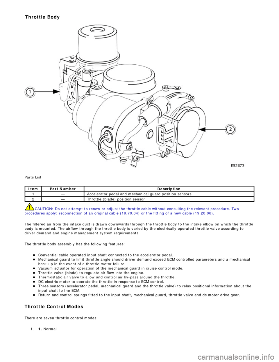
P
arts List
CAUTION: Do not attempt to renew or adjust the throttle cable without consulting the relevant procedure. Two
procedures apply: reconnection of an original cable (19.70.04) or the fitting of a new cable (19.20.06).
The filtered air from the intake duct is drawn downwards through the throttle body to the intake elbow on which the throttle
body is mounted. The airflow through the throttle body is vari ed by the electrically operated throttle valve according to
driver demand and engine mana gement system requirements.
The throttle body assembly has the following features:
Con
vential cable operated input shaft connected to the accelerator pedal.
M
echanical guard to limit throttle angl
e should driver demand exceed ECM co ntrolled parameters and a mechanical
back-up in the event of a throttle motor failure.
Vacuum actuator for operation of the mech anical guard in cru
ise control mode.
Thr
ottle valve (blade) to regula
te air flow into the engine.
Thermostatic air valve to allow and con
t
rol air by-pass around the throttle.
D
C electric motor to operate the thro
ttle in response to ECM control.
Three
sensors (accelerator pedal, mechan
ical guard and the throttle valve) to relay positional information about the
input shaft to the ECM.
R
eturn and control springs fitted to th
e input shaft, mechanical guard, thro ttle valve and dc motor drive gear.
Throttle Cont
rol Modes
There are seven throttle control
modes:
1. 1. Normal
It
em
Par
t Number
De
scription
1—Acce
lerator pedal and mechanic
al guard position sensors
2—Throttl
e (blade)
position sensor
Throttle Body
Page 1110 of 2490
2.2. Cruise
3. 3. Mechanica l
guard
4. 4. Fixed idle
5. 5. Redundancy
6. 6. Full authority
7. 7. Engine shut-down
Normal mode occurs when the EC M uses the mechanical and monitoring arrangem ent of the throttle valve to control throttle
opening. The ECM does not permit driver demand to be exceeded but it can be restricted to allow for such features as
stability / traction control, or engine power limitation.
The ECM determines engine idle speed by controlling the throttle valve motor to vary the blade angle between the non-
adjustable preset limits of the mechanic al guard and the throttle valve motor.
Cruise mode is engaged as a result of the ECM calculating and controlling the required throttle valve opening via the
vacuum system. When the driver releases the throttle pedal, the input shaft disengages from the mechanical guard or the
vacuum actuator pulls the guard away from th e throttle valve. The throttle pedal will feel light should it be pushed again to
accelerate (pressing the pedal further will re-engage the input shaft with the mechanical guard and restore normal feel).
The ECM utilizes sensors to monitor the relative positions of the mechanical guard and throttle valve and adjusts them to
maintain the set cruise speed.
Mechanical guard mode permits full mechanical operation of the throttle if the ECM detects that a problem has been
encountered with the throttle valve position sensor, dc motor, associated harnesses / connecto rs or the ECM.
Fixed idle mode occurs when any two of the three sensors (two input shaft sensors and the mechanical guard sensor) fail.
The ECM will assume values which represent a blade angl e of approximately 2,5° and 1200 rpm (unloaded) maximum
engine speed.
Redundancy mode occurs when any one of the three sensors (two input shaft sensors and the mechanical guard sensor)
fails. The operational pair will be deemed to be safe to co ntinue without intervention, but cruise will be inhibited.
Full authority mode is invoked when a mech anical guard failure occurs which indicates that the guard is stuck fully open.
The red warning lamp will be lit and road speed will be li mited to 120 kph.
Engine shut-down mode will occur followin g multiple failures, such as mechanical guard mode following full authority mode
(or vice versa) or the throttle blade sticks.
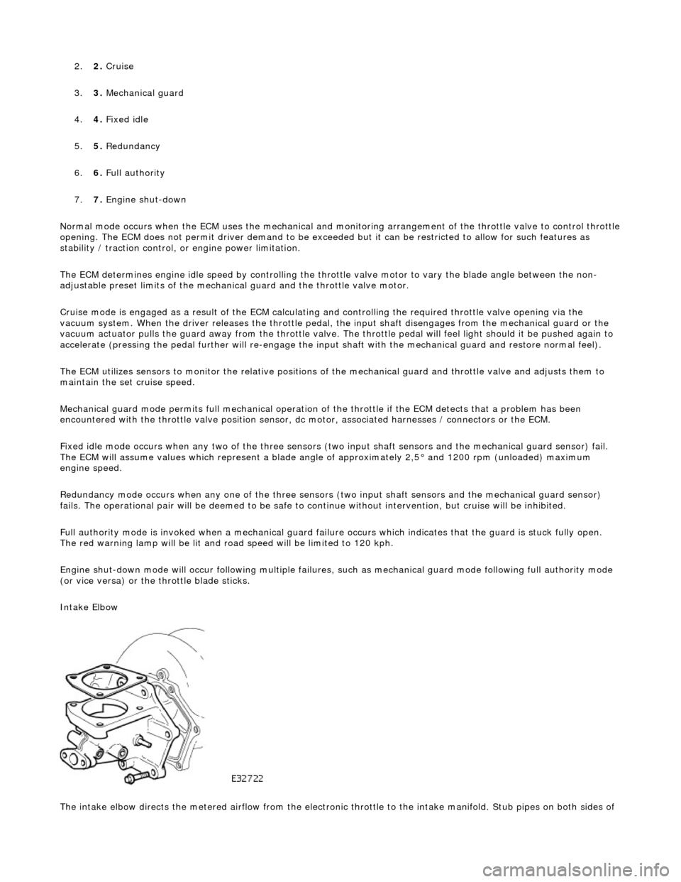
Intake Elbow
The intake elbow directs the metered airflow from the electronic throttle to the intake manifold. Stub pipes on both sides of
Page 1111 of 2490
the
intake elbow provide connections for vacuum actuators and are also used to redirect emissions into the engine.
On the right-hand side of the elbow a la rge diameter pipe connects to the brake servo. The smaller pipe provides a vacuum
feed to the fuel rail pressure regulator and throttle cruise control system. On the le ft-hand side of the elbow the front pipe
supplies vacuum control for the evaporative emissions system valves.
Emissions from the engine part load breather (bank 2) and pu rged fuel vapor from the EVAP valve are drawn via a common
T piece into the left-hand side of the intake elbow. Re-cir culated exhaust gas enters the intake elbow via the EGR valve
which is mounted directly on the rear of the elbow : where the EGR system is not used, a blanking plate is fitted.
The fuel system, throttle and emission control system s are described more fully in the relevant sections.
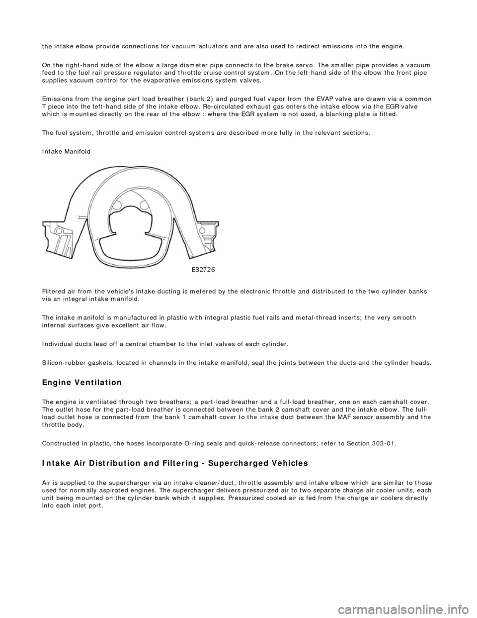
Intake Manifold
Filtered air from the vehicle's intake ducting is metered by th e electronic throttle and distributed to the two cylinder banks
via an integral intake manifold.
The intake manifold is manufactured in plastic with integral plastic fuel rails and metal-thread inserts; the very smooth
internal surfaces give excellent air flow.
Individual ducts lead off a central chamber to the inlet valves of each cylinder.
Silicon-rubber gaskets, loca ted in channels in the intake manifold, seal th e joints between the ducts and the cylinder heads.
Engine Ventilation
The e
ngine is ventilated through two brea
thers; a part-load breather and a full-load breather, one on each camshaft cover.
The outlet hose for the part-load breather is connected between the bank 2 camshaft cover and the intake elbow. The full-
load outlet hose is connected from the bank 1 camshaft cover to the intake duct between the MAF sensor assembly and the
throttle body.
Constructed in plastic, the hoses incorporate O-ring seal s and quick-release connectors; refer to Section 303-01.
I
ntake Air Distribution and Filtering - Supercharged Vehicles
Ai
r is supplied to the supercharger via an
intake cleaner/duct, throttle assembly and intake elbow which are similar to those
used for normally aspirated engines. The su percharger delivers pressurized air to two separate charge air cooler units, each
unit being mounted on the cy linder bank which it supplies. Pr essurized cooled air is fed from the charge air coolers directly
into each inlet port.