sensor JAGUAR X308 1998 2.G Workshop Manual
[x] Cancel search | Manufacturer: JAGUAR, Model Year: 1998, Model line: X308, Model: JAGUAR X308 1998 2.GPages: 2490, PDF Size: 69.81 MB
Page 1112 of 2490
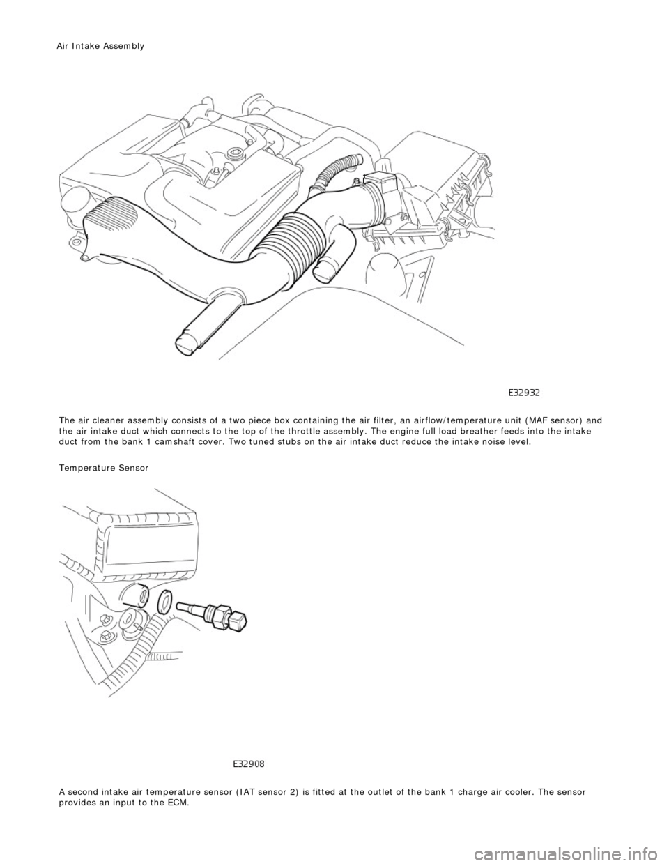
The air cleaner assembl y
consists of a tw
o piece box containing the ai r filter, an airflow/temperature unit (MAF sensor) and
the air intake duct which connects to the top of the throttle assembly. The engine full load breather feeds into the intake
duct from the bank 1 camshaft cover. Two tuned stubs on the air intake duct reduce the intake noise level.
Temperature Sensor
A second intake air temperature sensor (IAT sensor 2) is fitted at the outlet of the bank 1 charge air cooler. The sensor
provides an input to the ECM.
Air Intake Asse mbly
Page 1114 of 2490
P a
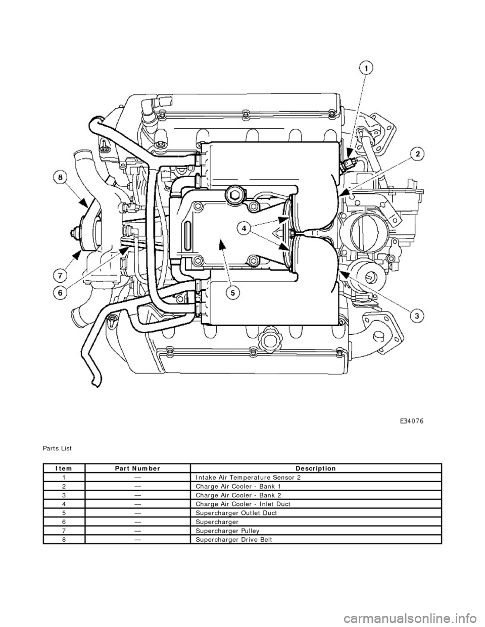
rts List
It
e
m
Par
t
Number
De
scr
iption
1—Inta
k
e Air Temperature Sensor 2
2—Charge Air Cooler - Bank 1
3—Charge Air Cooler - Bank 2
4—Charge Air Cooler - Inlet Duct
5—Supercharger
Outlet D
uct
6—Supercharger
7—Supercharger
Pull
ey
8—Supercharger
Dri
ve Belt
Page 1122 of 2490
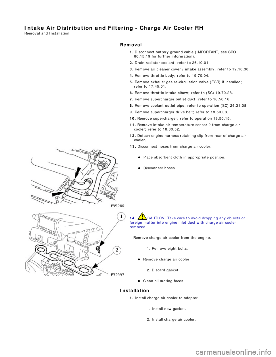
Intake Air Distribution and Filtering - Charge Air Cooler RH
Remo
val and Installation
Remov
a
l
Installation
1. Disc onne
ct battery ground cable (IMPORTANT, see SRO
86.15.19 for further information).
2. Drain radiator coolant; refer to 26.10.01.
3. Remove air cleaner cover / intake assembly; refer to 19.10.30.
4. Remove throttle body; refer to 19.70.04.
5. Remove exhaust gas re-circulation valve (EGR) if installed;
refer to 17.45.01.
6. Remove throttle intake elbo w; refer to (SC) 19.70.28.
7. Remove supercharger outlet duct; refer to 18.50.16.
8. Remove coolant outlet pipe; refe r to operation (SC) 26.31.08.
9. Remove supercharger drive belt; refer to 18.50.08.
10. Remove supercharger; refer to operation 18.50.15.
11. Remove intake air temperatur e sensor 2 from charge air
cooler; refer to 18.30.52.
12. Detach engine harness retaining clip from rear of charge air
cooler.
13. Di
sconnect hoses from charge air cooler.
Pla
ce absorbent cloth in appropriate position.
Di
sc
onnect hoses.
14 . CAUTI
ON: Take care to avoi
d dropping any objects or
foreign matter into engine inle t duct with charge air cooler
removed.
Remove charge air cooler from the engine. 1. Remove eight bolts.
Remove charge air cooler.
2
. Discard gasket.
Cle
a
n all mating faces.
1.
Install ch arge air
cooler to adaptor.
1. Install new gasket.
2. Install charge air cooler.
Page 1123 of 2490
2.
Conne
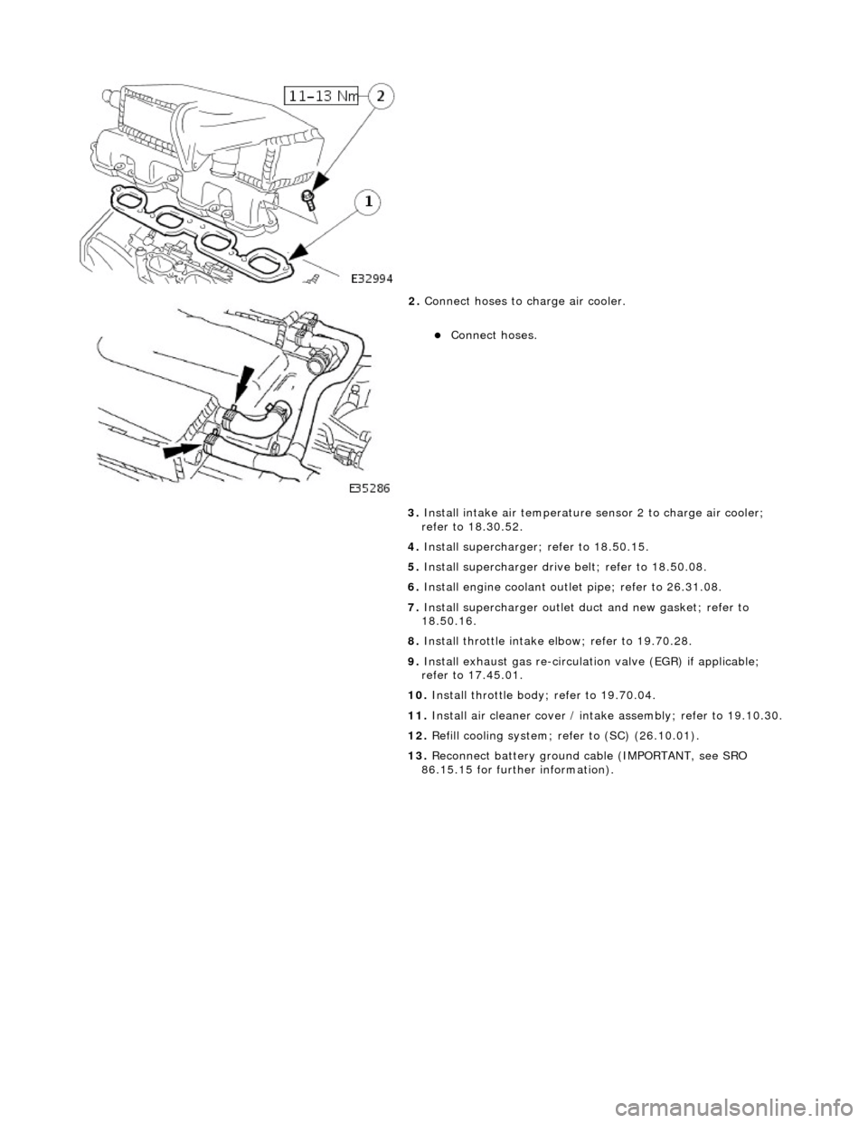
ct hoses to charge air cooler.
Conne
ct hoses.
3. Install intake air te mperature sensor 2 to charge air cooler;
refer to 18.30.52.
4. Install supercharger; refer to 18.50.15.
5. Install supercharger driv e belt; refer to 18.50.08.
6. Install engine coolant outlet pipe; refer to 26.31.08.
7. Install supercharger outlet du ct and new gasket; refer to
18.50.16.
8. Install throttle intake elbow; refer to 19.70.28.
9. Install exhaust gas re-circulation valve (EGR) if applicable;
refer to 17.45.01.
10. Install throttle body; refer to 19.70.04.
11. Install air cleaner cover / intake assembly; re fer to 19.10.30.
12. Refill cooling system; refer to (SC) (26.10.01).
13. Reconnect battery ground cable (IMPORTANT, see SRO
86.15.15 for further information).
Page 1126 of 2490
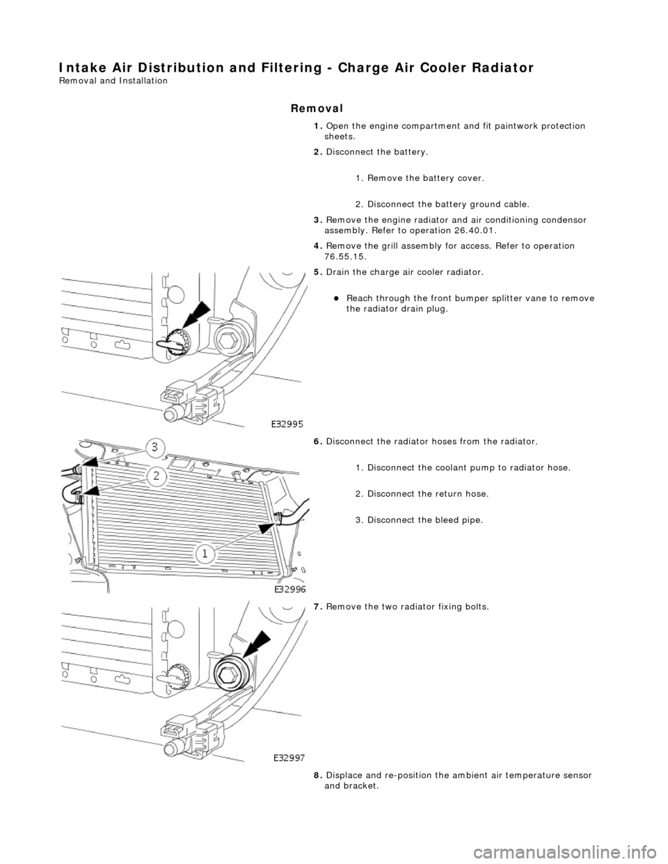
Intake Air Distribution and Filtering - Charge Air Cooler Radiator
Remo
val and Installation
Remov
a
l
1.
Op
en the engine compartment and fit paintwork protection
sheets.
2. Disconnect the battery.
1. Remove the battery cover.
2. Disconnect the battery ground cable.
3. Remove the engine radiator and air conditioning condensor
assembly. Refer to operation 26.40.01.
4. Remove the grill assembly fo r access. Refer to operation
76.55.15.
5. Drain th e charge air cooler radiator.
Reach t
hrough the front bumper
splitter vane to remove
the radiator drain plug.
6. Disc
onnect the radiator
hoses from the radiator.
1. Disconnect the coolant pump to radiator hose.
2. Disconnect the return hose.
3. Disconnect the bleed pipe.
7. Re
move the two radiator fixing bolts.
8. Displace and re-position the am bient air temperature sensor
and bracket.
Page 1127 of 2490
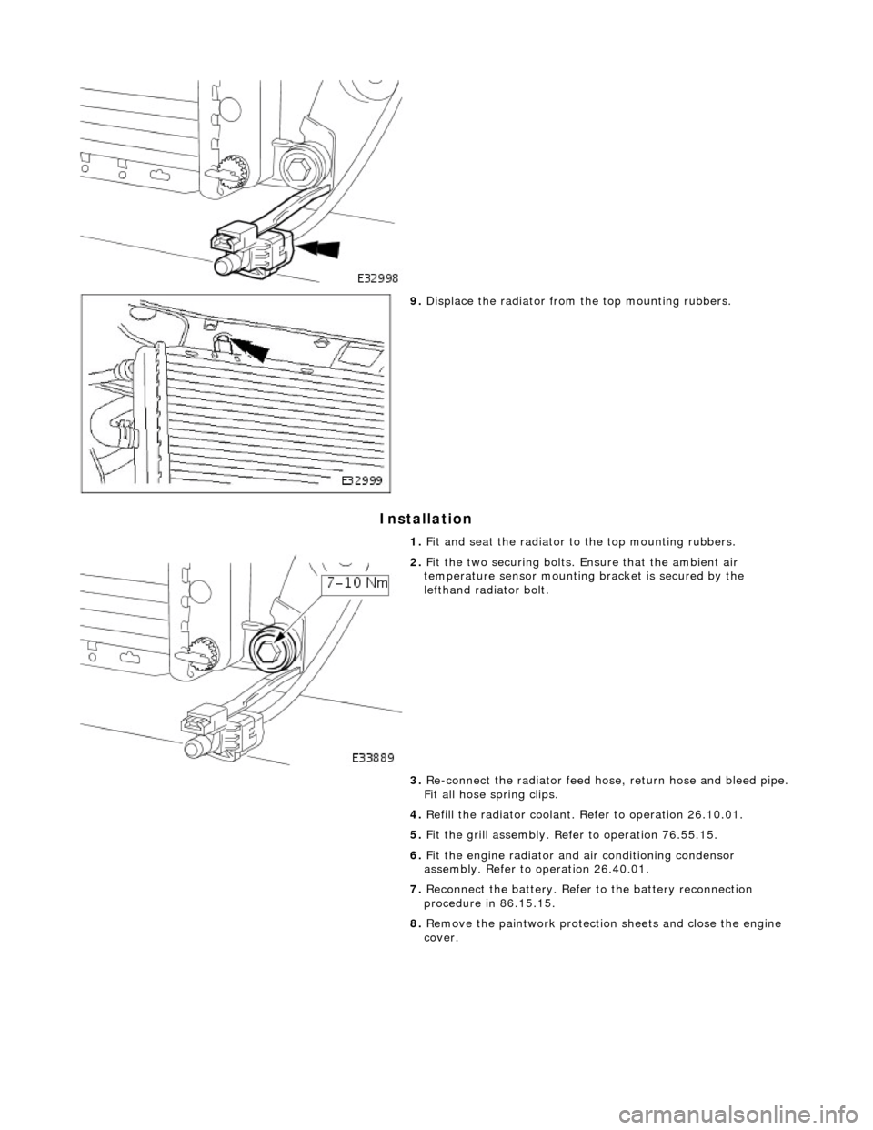
I
nstallation
9.
Di
splace the radiator from
the top mounting rubbers.
1. Fit and seat the radiator to the top mounting rubbers.
2. F
it the two securing bolts.
Ensure that the ambient air
temperature sensor mounting bracket is secured by the
lefthand radiator bolt.
3. Re-connect the radiator feed ho se, return hose and bleed pipe.
Fit all hose spring clips.
4. Refill the radiator coolant. Refer to operation 26.10.01.
5. Fit the grill assembly. Refer to operation 76.55.15.
6. Fit the engine radiator and air conditioning condensor
assembly. Refer to operation 26.40.01.
7. Reconnect the battery. Refer to the battery reconnection
procedure in 86.15.15.
8. Remove the paintwork protection sheets and close the engine
cover.
Page 1149 of 2490
The E
VAP canister purge valve controls th
e flow rate of fuel vapour drawn into the engine during the canister purge
operation. The valve is opened by a vacu um feed from the induction elbow : the vacu um feed is controlled by the integral
valve solenoid and is applied when the so lenoid is energised. The solenoid is pulsed on (energised) and off by a fixed
frequency (100Hz) variable pulse width control signal (pulse width modulation). By varying the pulse on to off time, the
ECM controls the duty cycle of the valve (time that the valve is open to time closed) and thus the vapour flow rate to the
engine.
With no ECM signal applied to the va lve solenoid, the valve remains closed.
Can
ister Purge Operation
The
following pre-conditions are ne
cessary for purging to commence :
aft
er battery disconnection/reconnection, engine
management adaptations must be re-instated.
engine has run for
at least 8 seconds.
engi
ne coolant temperature is not less than 70 °C.
engine
not running in the fuel
cut off condition (eg overrun).
t
he adaptive fuel correction
function has not registered a rich or lean failure
t
he evaporative emission leak test has not failed
no faults have been diagnosted in th
e rel
evant sensor and valve circuits -
Air Flow Meter (AFM), Engine Coolant
Temperature sensor, Evaporativ e Canister Purge valve and Canister Close Valve (CCV).
If these conditions have been satisfied, purging is started. If any failures are registered, purging is inhibited.
The canister(s) is purged during each driv e cycle at various rates in accordance with the prevailing engine conditions. The
engine management software st ores a map of engine speed (RPM) against engine load (grams of air inducted / rev). For
any given engine speed and load, a vapour purge rate is assigned (purge rate increases with engine speed and load).
The preset purge rates are base d on the assumption of a vapour concentratio n of 100%. The actual amount of vapour is
measured by the closed loop fueling system : the input of evaporative fuel into the engine causes the outputs from the
upstream oxygen sensors to change, the am ount of change providing a measure of the vapour concentration. This feedback
causes the original purge rate to be adju sted and also reduces the amount of fuel input via the injectors to maintain the
correct air to fuel ratio.
Engine speed/load mapping and the corresp onding purge rates are different for single canister, running loss and ORVR
evaporative systems.
Page 1152 of 2490
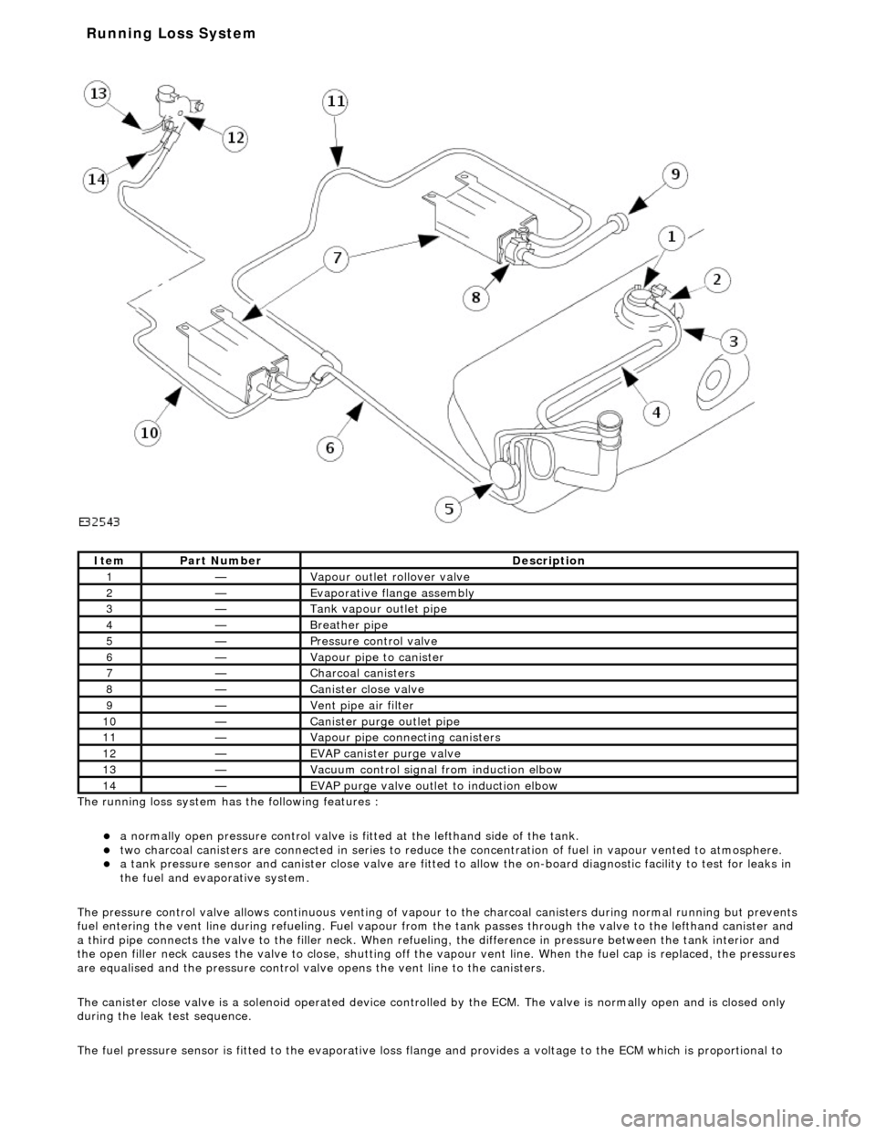
The ru nning loss
system has the following features :
a
normall
y open pressure control valve is fi
tted at the lefthand side of the tank.
two charcoal
canisters are connected in series to reduce th
e concentration of fuel in vapour vented to atmosphere.
a t
ank pressure sensor and canister close
valve are fitted to allow the on-board di agnostic facility to test for leaks in
the fuel and evaporative system.
The pressure control valve allows continuo us venting of vapour to the charcoal canisters during normal running but prevents
fuel entering the vent line duri ng refueling. Fuel vapour from the tank passes through the valve to the lefthand canister and
a third pipe connects the valve to the fill er neck. When refueling, the difference in pressure betw een the tank interior and
the open filler neck causes the valve to cl ose, shutting off the vapour vent line. Wh en the fuel cap is replaced, the pressures
are equalised and the pressure control valve opens the vent line to the canisters.
The canister close valve is a solenoid operated device controlled by the ECM. The valve is normally open and is closed only
during the leak test sequence.
The fuel pressure sensor is fitted to th e evaporative loss flange and provides a volt age to the ECM which is proportional to
Ite
m
Par
t
Number
De
scr
iption
1—Vapour outl
et rol
lover valve
2—Evaporative flan
ge assembly
3—Tank vapour outlet pipe
4—Breather pipe
5—Pressure control
valve
6—Vapour pipe to canister
7—Charcoal cani
sters
8—Cani
st
er close valve
9—Vent pi
pe ai
r filter
10—Canister purge ou
tlet pipe
11—Vapour pipe conn
ecting canisters
12—EVAP canister purge v
a
lve
13—Vacuu
m
control signal from induction elbow
14—EVAP pu
rge valve outlet to induction elbow
Running Loss Sys
tem
Page 1153 of 2490
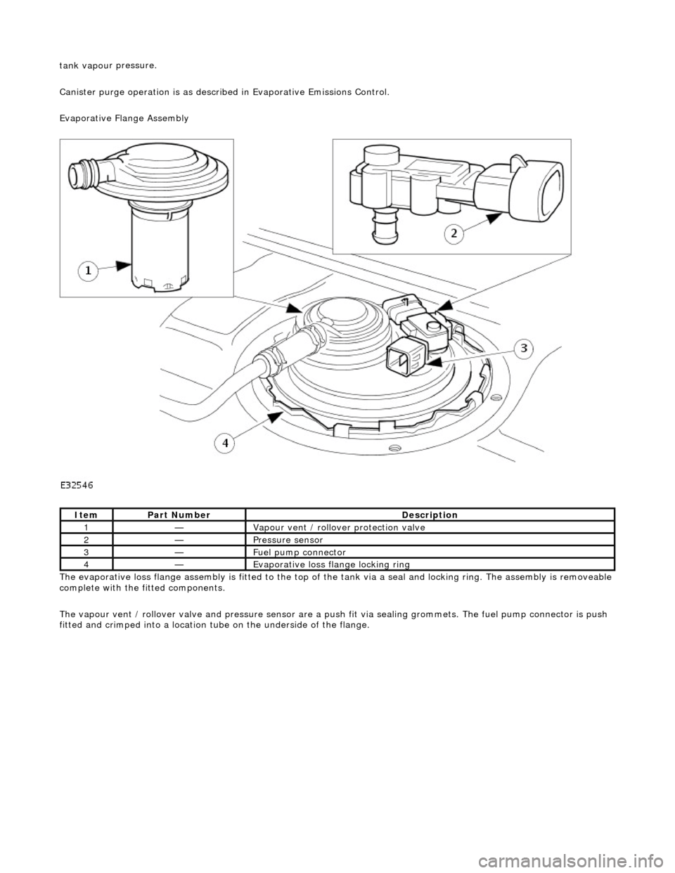
tank vapou
r pressure.
Canister purge operation is as described in Evaporative Emissions Control.
Evaporative Flange Assembly
The evaporative loss flange assembly is fitted to the top of the tank via a seal and locking ring. The assembly is removeable
complete with the fitted components.
The vapour vent / rollover valve and pressure sensor are a pu sh fit via sealing grommets. The fuel pump connector is push
fitted and crimped into a location tu be on the underside of the flange.
It
em
Par
t Number
De
scription
1—Vapour vent /
rollover protection valve
2—Pres
sure sensor
3—Fue
l pump connector
4—Evaporative loss flange locking rin
g
Page 1156 of 2490
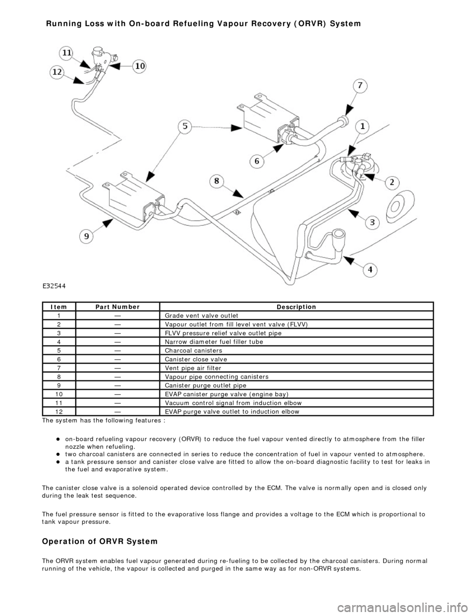
The system has the
following features :
o
n
-board refueling vapour recovery (ORVR) to reduce the fu
el vapour vented directly to atmosphere from the filler
nozzle when refueling.
two ch arcoal
canisters are connected in series to reduce th
e concentration of fuel in vapour vented to atmosphere.
a t
ank pressure sensor and canister close
valve are fitted to allow the on-board di agnostic facility to test for leaks in
the fuel and evaporative system.
The canister close valve is a solenoid operated device controlled by the ECM. The valve is normally open and is closed only
during the leak test sequence.
The fuel pressure sensor is fitted to th e evaporative loss flange and provides a volt age to the ECM which is proportional to
tank vapour pressure.
Op era
tion of ORVR System
The ORVR system enabl
e
s fuel vapour generated during re-fueling to be collected by
the charcoal canisters. During normal
running of the vehicle, the vapour is collected and purged in the same way as for non-ORVR systems.
Ite
m
Par
t
Number
De
scr
iption
1—Grade vent
valve outl
et
2—Vapour outl
et from fil
l level vent valve (FLVV)
3—F
L
VV pressure relief valve outlet pipe
4—N
a
rrow diameter fuel filler tube
5—Charcoal can
i
sters
6—Cani
st
er close valve
7—Vent pi
pe ai
r filter
8—Vapour pipe
conn
ecting canisters
9—Canister purge ou
tlet pipe
10—EVAP canister purge v a
lve (engine bay)
11—Vacuu
m
control signal from induction elbow
12—EVAP pu
rge valve outlet to induction elbow
Running Loss with On-board R
efuelin
g Vapour Recovery (ORVR) System