sensor JAGUAR X308 1998 2.G Workshop Manual
[x] Cancel search | Manufacturer: JAGUAR, Model Year: 1998, Model line: X308, Model: JAGUAR X308 1998 2.GPages: 2490, PDF Size: 69.81 MB
Page 1158 of 2490
The fuel fil
ler cap is the same as
that used on non-ORVR systems.
The check valve assembly is a push fit into the end of the fuel filler tube and is accessible with the evaporative flange
removed. The valve has a light spring load ing and opens under the inflow of fuel.
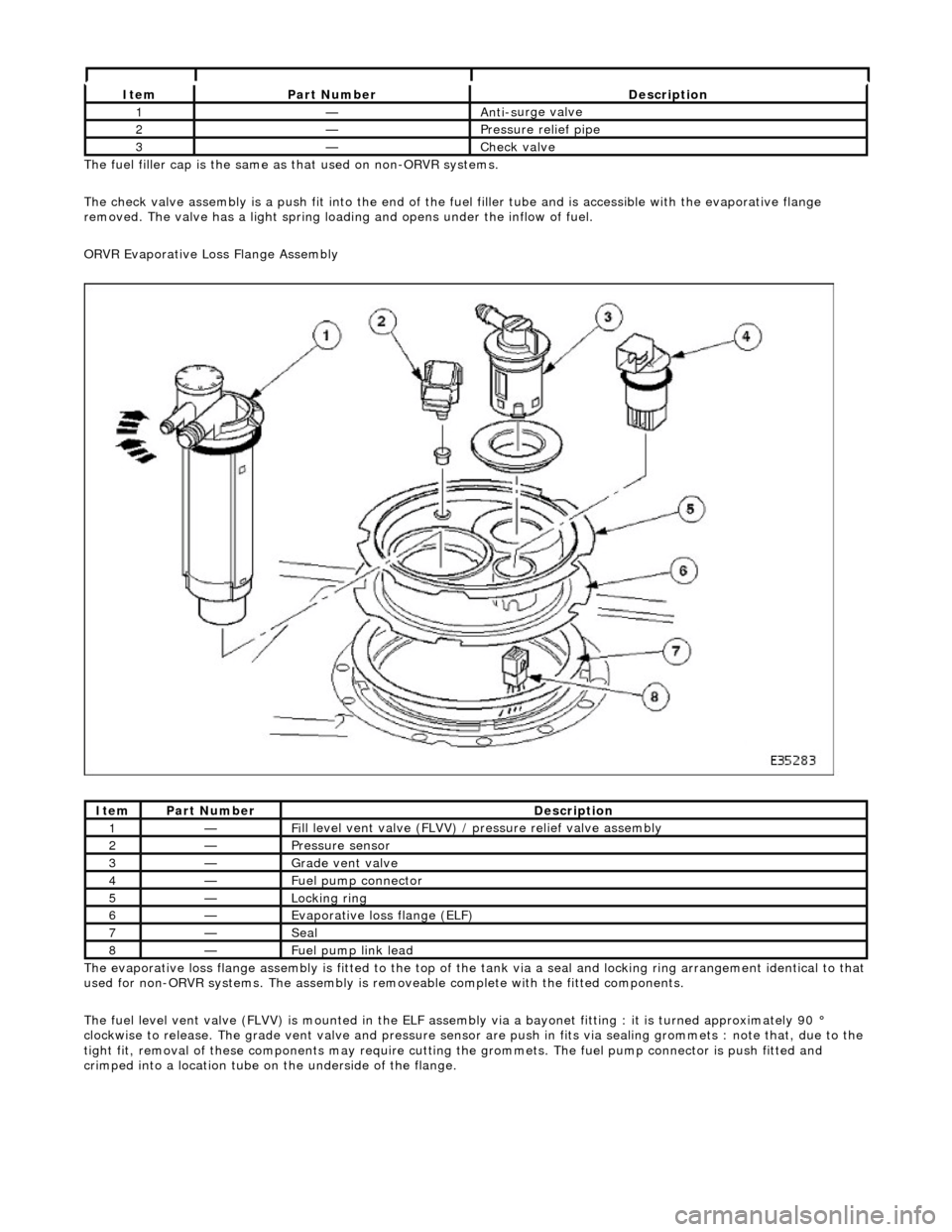
ORVR Evaporative Loss Flange Assembly
The evaporative loss flange assembly is fitted to the top of the tank via a seal and locking ring arrangement identical to that
used for non-ORVR systems. The assembly is re moveable complete with the fitted components.
The fuel level vent valve (FLVV) is mounted in the ELF assembly via a bayonet fitting : it is turned approximately 90 °
clockwise to release. The grade vent valve and pressure sensor are push in fits via sealing gromme ts : note that, due to the
tight fit, removal of these components may require cutting the grommets. The fuel pump connector is push fitted and
crimped into a location tube on the underside of the flange.
It e
m
Par
t
Number
De
scr
iption
1—An
ti-s
urge valve
2—Pressure rel
i
ef pipe
3—Check v
a
lve
It
e
m
Par
t
Number
De
scr
iption
1—Fi
ll
level vent valve (FLVV) /
pressure relief valve assembly
2—Pres
sure
sensor
3—Grade vent
valve
4—Fue
l
pump connector
5—Lockin
g rin
g
6—Evaporative loss flange (ELF)
7—Seal
8—F
u
el pump link lead
Page 1160 of 2490
Ite
m
Part
Number
Descr
iption
1—Fu
el tank pressure sensor (if applicable)
2—Engine m
anagement ECU
3—EVAP canister purge va
lve
4—EVAP ca
nister close valve (if applicable)
5—Engine
mana
gement fusebox - IGN supply
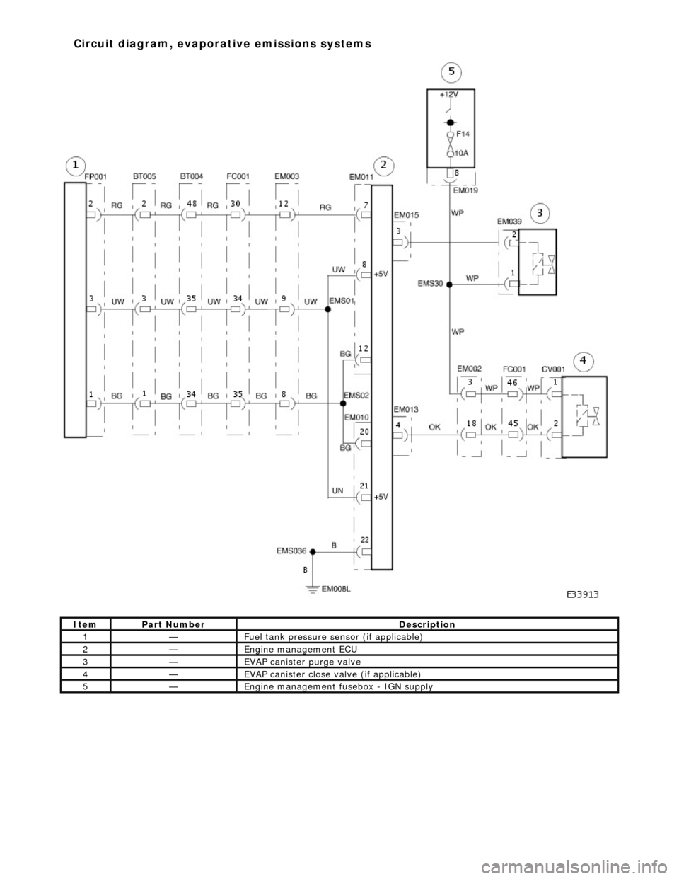
Circuit diagram
,
evaporative emissions systems
Page 1162 of 2490
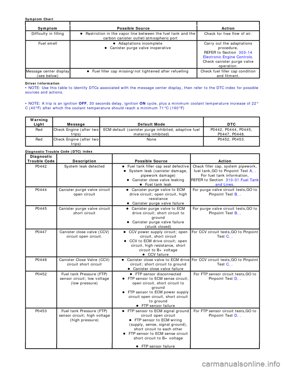
Driver Info
rmation
•
NOTE: Use this table to identify DTCs associated with the me
ssage center display, then refer to the DTC index for possible
sources and actions.
• NOTE: A trip is an ignition OFF, 30 seconds delay, ignition ON cycle, plus a minimum coolant temperature increase of 22°
C (40°F) after which the coolant temperat ure should reach a minimum 71°C (160°F)
Diagnostic Trouble C
ode (DTC) index
Sy
m
ptom
Possib
l
e Source
Acti
o
n
D
i
fficulty in filling
R
e
striction in the vapor line between the fuel tank and the
carbon canister outlet/atmospheric port
Check f or free f
low of air.
F
u
el smell
Adaptat
i
ons incomplete
Cani
st
er purge valve inoperative
Carry
o
ut the adaptations
procedure,
REFER to Section 303
-14 Ele c
tronic Engine Controls
.
Chec k cani
ster purge valve
operation.
M e
ssage center display
(see below)
Fue l
filler cap missing/not
tightened after refuelling
Check fu
el filler cap condition
and fitment.
Warning Li
ght
Mess
age Defaul
t Mode
DT
C
RedCheck Engine (after two
trip
s)
ECM de
fa
ult (canister purge inhibited, adaptive fuel
metering inhibited)
P0442,
P0444, P0445,
P0447, P0448.
Re dCheck Engine (after two
trip
s)
No
neP04 52,
P0453.
Di
agno
stic
Trouble Code
De scr
iption
Possib
l
e Source
Acti
o
n
P0442Sy
st
em leak detected
F
u
el tank filler cap seal defective
Sy
ste
m leak (c
anister damage,
pipework damage)
Cani st
er close valve leaking
F
u
el tank leak
Chec
k fi
ller cap,
system pipework,
fuel tank,GO to Pinpoint Test A.
.
F o
r fuel tank information,
REFER to Section 310
-01 Fu
el Tank
and Lines.
P0444Canist
er purge valve circuit
open circuit
Cani st
er purge valve to ECM
drive circuit; open circuit, high
resistance
Cani st
er purge valve failure
F
or purge
valve circuit tests,GO to
Pinpoint Test B.
.
P0445Canist
er purge valve circuit
short circuit
Cani st
er purge valve to ECM
drive circuit; short circuit to ground
Canist
er purge valve failure
(stuck closed)
F or purge
valve circuit tests,GO to
Pinpoint Test B.
.
P0447Canist
er close valve (CCV)
circuit open circuit.
CCV power su pply ci
rcuit; open
circuit, short circuit
CCV to ECM drive circuit;
open
circuit, high resistance, short circuit to B+ voltage
CCV failure
Fo
r CCV circuit tests,GO to Pinpoint
Test C.
.
P0448Canist
er Close Valve (CCV)
circuit short circuit
Cani st
er close valve to ECM drive
circuit; short circuit to ground
Cani st
er close valve failure
F
o
r CCV circuit tests,GO to Pinpoint
Test C.
.
P0452 Fu
el tank Pressure (FTP)
sensor circuit; low voltage (low pressure)
FTP sen
sor disconnected
FTP sen
sor to ECM sense circuit;
open circuit, short circuit to ground
FTP sens
or to ECM power supply
circuit open circuit, short circuit to ground
FT
P sensor failure
For FT
P se
nsor circuit tests,GO to
Pinpoint Test D.
.
P0453Fu
el tank Pressure (FTP)
sensor circuit; high voltage
(high pressure)
FTP sen
sor to ECM signal ground
circuit open circuit
F T
P sensor to ECM wiring
(supply, sense, signal ground),
short circuit to each other
FTP sen
sor to ECM sense circuit
short circuit to B+ voltage
For FT P se
nsor circuit tests,GO to
Pinpoint Test D.
.
FT
P sensor failure
Sym
ptom Chart
Page 1164 of 2490
"d
iagnostic drive cycles" above.
No GO to B2
.
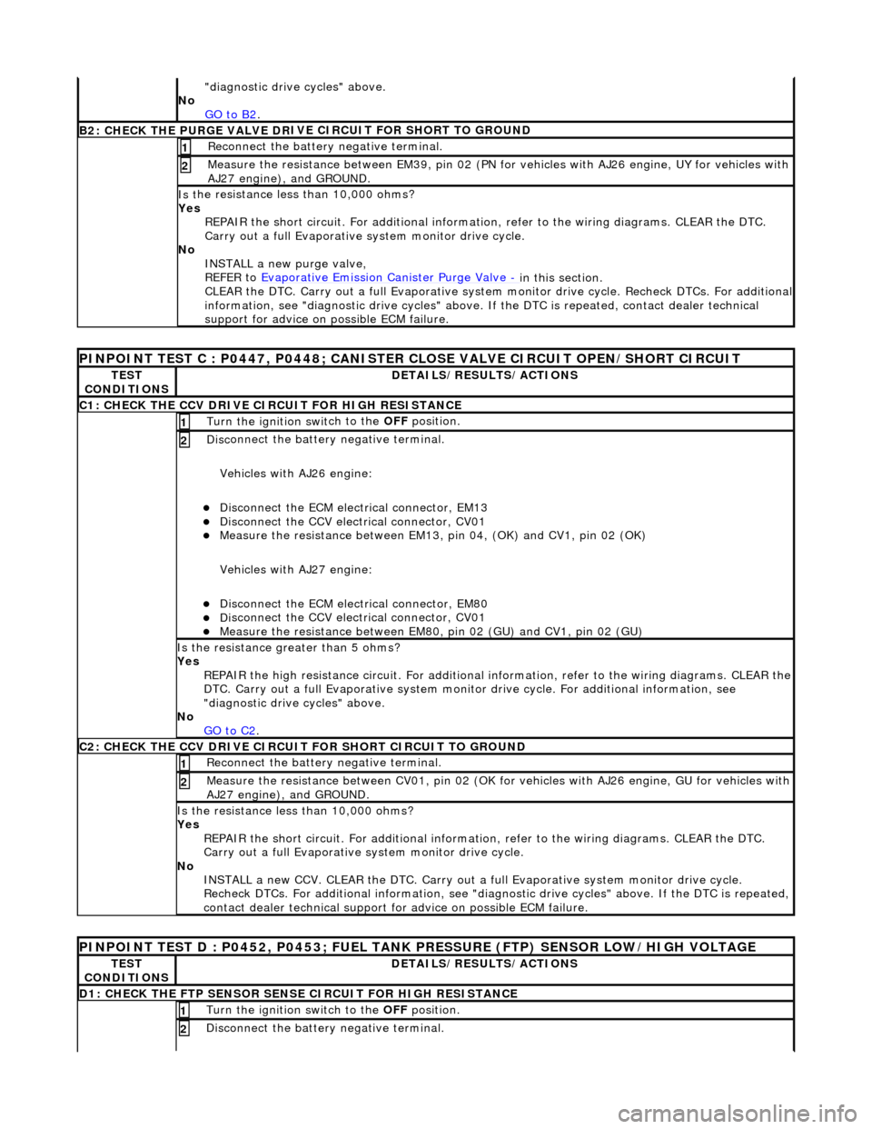
B2: CHECK THE PURGE VALVE DR
IV
E CIRCUIT FOR SHORT TO GROUND
Re
connect the battery negative terminal.
1
Meas
ure t
he resistance between EM39, pin 02 (PN for vehicles with AJ26
engine, UY for vehicles with
AJ27 engine), and GROUND.
2
Is t
he resistance less than 10,000 ohms?
Yes REPAIR the short circuit. For addi tional information, refer to the wiring diagrams. CLEAR the DTC.
Carry out a full Evaporative system monitor drive cycle.
No INSTALL a new purge valve,
REFER to Evaporative Emission Canister Purge Valve
- in thi
s section.
CLEAR the DTC. Carry out a full Evaporative system monitor drive cycle. Recheck DTCs. For additional
information, see "diagnostic drive cycles" above. If the DTC is repeated, contact dealer technical
support for advice on possible ECM failure.
PI
NPOINT TEST C : P0447, P0448; CANISTER CLOSE VALVE CIRCUIT OPEN/SHORT CIRCUIT
TE
S
T
CONDITIONS
D E
TAILS/RESULTS/ACTIONS
C1
: CH
ECK THE CCV DRIVE CIRCUIT FOR HIGH RESISTANCE
Turn the ignition swi
t
ch to the
OFF position.
1
Disc
onnect the battery negative terminal.
Vehicles with AJ26 engine:
Disc onne
ct the ECM electrical connector, EM13
Di
sc
onnect the CCV electrical connector, CV01
Meas
ure t
he resistance between EM13, pi
n 04, (OK) and CV1, pin 02 (OK)
Vehicles with AJ27 engine:
Disc onne
ct the ECM electrical connector, EM80
Di
sc
onnect the CCV electrical connector, CV01
Meas
ure t
he resistance between EM80,
pin 02 (GU) and CV1, pin 02 (GU)
2
Is the res
istance greater than 5 ohms?
Yes REPAIR the high resistance circuit. For additional information, refer to the wiring diagrams. CLEAR the
DTC. Carry out a full Evaporative system monitor drive cycle. For additional information, see
"diagnostic drive cycles" above.
No GO to C2
.
C2: CH
ECK THE CCV DRIVE CIRCUI
T FOR SHORT CIRCUIT TO GROUND
Re
connect the battery negative terminal.
1
Meas
ure t
he resistance between CV01,
pin 02 (OK for vehicles with AJ26 engine, GU for vehicles with
AJ27 engine), and GROUND.
2
Is t
he resistance less than 10,000 ohms?
Yes REPAIR the short circuit. For addi tional information, refer to the wiring diagrams. CLEAR the DTC.
Carry out a full Evaporative system monitor drive cycle.
No INSTALL a new CCV. CLEAR the DTC. Carry out a fu ll Evaporative system monitor drive cycle.
Recheck DTCs. For additional inform ation, see "diagnostic drive cycles" above. If the DTC is repeated,
contact dealer technical support for advice on possible ECM failure.
P INPOINT TES
T D : P0452, P0453; FUEL TANK
PRESSURE (FTP) SENSOR LOW/HIGH VOLTAGE
TES
T
CONDITIONS
DE
TAILS/RESULTS/ACTIONS
D
1:
CHECK THE FTP SENSOR SENSE CIRCUIT FOR HIGH RESISTANCE
Turn the ignition swi
t
ch to the OFF
position.
1
Disc
onnect the battery negative terminal.
2
Page 1165 of 2490

Vehicles with AJ26 en
gine:
D
isconnect the ECM electrical connector, EM11
Di
sconnect the FTP sensor electrical connector, FP01
Meas
ure the resistance between EM11,
pin 07 (RG) and FP01, pin 02 (RG)
Vehicles with AJ27 engine:
D
isconnect the ECM electrical connector, EM81
Di
sconnect the FTP sensor electrical connector, FP01
Meas
ure the resistance between EM81,
pin 16 (RG) and FP01, pin 02 (RG)
Is th
e resistance greater than 5 ohms?
Yes REPAIR the high resistance circuit. For additional information, refer to the wiring diagrams. CLEAR the
DTC. Carry out a full Evaporative system monitor drive cycle. For additional information, see
"diagnostic drive cycles" above.
No GO to D2
.
D2: CHECK
THE FTP SENSOR SENSE CI
RCUIT FOR SHORT CIRCUIT TO GROUND
R
econnect the battery negative terminal.
1
Meas
ure the resistance between
FP01, pin 07 (RG) and GROUND.
2
Is
the resistance less than 10,000 ohms?
Yes REPAIR the short circuit. For addi tional information, refer to the wiring diagrams. CLEAR the DTC.
Carry out a full Evaporative system monitor drive cycle.
No GO to D4
.
D3: CHECK
THE FTP SENSOR SENSE CIRCUI
T FOR SHORT CIRCUIT TO HIGH VOLTAGE
Turn the ignition swi
tch to the ON
position.
1
Measure the
voltage between FP
01, pin 02 (RG) and GROUND.
2
Is th
e voltage greater than 3 volts?
Yes REPAIR the short circuit. For addi tional information, refer to the wiring diagrams. CLEAR the DTC.
Carry out a full Evaporative system monitor drive cycle.
No GO to D4
.
D
4: CHECK THE FTP SENSOR SIGNAL GROUND CIRCUIT FOR HIGH RESISTANCE
Di
sconnect the battery negative terminal.
Vehicles with AJ26 engine:
D
isconnect the ECM electrical connector, EM10
Meas
ure the resistance between EM11, pin 12 (BG) and FP01, pin 01 (BG)
Meas
ure the resistance between EM10, pin 20 (BG) and FP01, pin 01 (BG)
Vehicles with AJ27 engine:
Re
connect the ECM electrical connector, EM81
D
isconnect the ECM electrical connector, EM82
D
isconnect the ECM electrical connector, EM83
Meas
ure the resistance between EM82, pin 07 (BG) and FP01, pin 01 (BG)
Meas
ure the resistance between EM83, pin 13 (BG) and FP01, pin 01 (BG)
1
Is either resi
stance
greater than 5 ohms?
Yes REPAIR the high resistance circui t. This circuit includes harness splice, EMS02. For additional
information, refer to the wiring diagrams. CLEAR the DTC. Carry out a full Evaporative system
monitor drive cycle. For additional informat ion, see "diagnostic drive cycles" above.
No GO to D5
.
D5:
CHECK THE FTP SENSOR SIGNAL GROUND
CIRCUIT FOR SHORT CIRCUIT TO GROUND
R
econnect the battery negative terminal.
1
Meas
ure the resistance between
FP01, pin 01 (BG) and GROUND.
2
Is
the resistance less than 10,000 ohms?
Page 1166 of 2490

Yes
R
EPAIR the short circuit. For addi
tional information, refer to the wiring diagrams. CLEAR the DTC.
Carry out a full Evaporative system monitor drive cycle.
No GO to D6
.
D6: CHECK
THE FTP SENSOR POWER SU
PPLY CIRCUIT FOR HIGH RESISTANCE
Disc
onnect the battery negative terminal.
Vehicles with AJ26 engine:
Measure t
he resistance between EM11,
pin 08 (UW) and FP01, pin 03 (UW)
Measure t
he resistance between EM10,
pin 21 (UW) and FP01, pin 03 (UW)
Vehicles with AJ27 engine:
Meas ure t
he resistance between EM82,
pin 01 (OY) and FP01, pin 03 (OY)
Measure t
he resistance between EM83,
pin 05 (OY) and FP01, pin 03 (OY)
1
Is either resistance greater
than 5 ohms?
Yes
REPAIR the high resistance circui t. This circuit includes harness splice, EMS01. For additional
information, refer to the wiring diagrams. CLEAR the DTC. Carry out a full Evaporative system
monitor drive cycle. For additional informat ion, see "diagnostic drive cycles" above.
No GO to D7
.
D7: CHECK
THE FTP SENSOR WIRING
FOR SHORT CIRCUIT TO EACH OTHER
Measure
the resistance between FP01, pins 01 (BG) and 02 (RG).
1
M
e
asure the resistance between FP01, pins 02 (RG) and 03 (UW).
2
Is either resi
stance le
ss than 10,000 ohms?
Yes REPAIR the short circuit. For addi tional information, refer to the wiring diagrams. CLEAR the DTC.
Carry out a full Evaporative system monitor drive cycle.
No INSTALL a new FTP sensor. CLEAR the DTC. Carry out a full Evaporative system monitor drive cycle.
For additional information, see "diagnostic drive cycles" above.
Page 1171 of 2490

E
vaporative Emissions - Fuel
Tank Pressure Sensor
Re
moval and Installation
Remov
al
Installation
1.
Disc
onnect battery ground cable (IMPORTANT, see SRO
86.15.19 for further information).
2. WARNING: BEFORE PROCEEDING, IT IS ESSENTIAL THAT
THE WARNING NOTES GIVEN IN SECTION 100-00 (UNDER THE
HEADING 'SAFETY PRECAUTIONS') ARE READ AND
UNDERSTOOD.
Drain the fuel tank using a suitab le suction pump/tanker. If the
On-board Refueling Vapor Recove ry (ORVR) system is fitted,
refer to General Procedures Section 310-01.
3. R
emove the fuel tank; refe
r to operation 19.55.01.
4. R
emove pressure sensor fro
m evaporative loss flange.
1. Installation is th e reverse of the re moval procedure.
Page 1175 of 2490

E
lectronic Engine Controls -
Torque spe
cification
Com
ponent
Nm
Engine
coolant temperature sensor
15
- 19
Camshaft position
sensor
9 -
11
Cranksh
aft position sensor
8 -
12
Knock
sensor
31
- 41
O
xygen sensor to downpipe
40
- 50
Inta
ke air temperature sensor (SC only)
30
- 40
Page 1177 of 2490
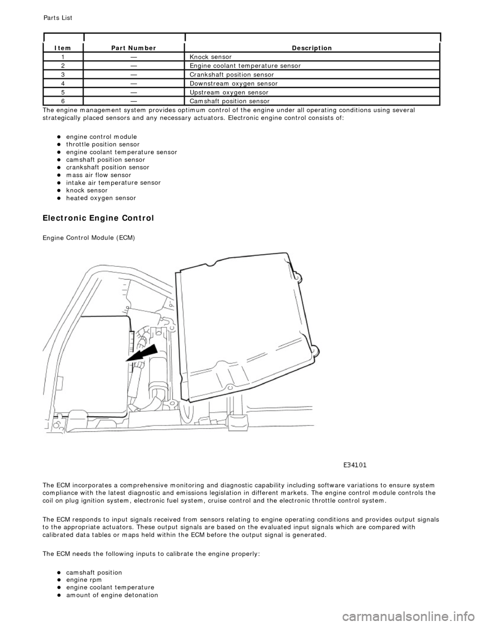
Th
e engine management system provides optimum control of
the engine under all operating conditions using several
strategically placed sensors and any necessary actuators. Electronic engine control consists of:
engine
control module
throttle posi
tion sensor
engi
ne coolant temperature sensor
cam
shaft position sensor
c
rankshaft position sensor
mass air
flow sensor
intake air temper
ature sensor
kn
ock sensor
heat
ed oxygen sensor
Electronic Engine Control
Engine
Control Module (ECM)
The ECM incorporates a comprehensive monitoring and diagnostic capability including software variations to ensure system
compliance with the latest diagnostic and emissions legislation in different markets. The engine control module controls the
coil on plug ignition system, electronic fuel system, cr uise control and the electronic throttle control system.
The ECM responds to input signals received from sensors relating to engine operatin g conditions and provides output signals
to the appropriate actuators. These outp ut signals are based on the evaluated input signals which are compared with
calibrated data tables or maps held within th e ECM before the output signal is generated.
The ECM needs the following inputs to calibrate the engine properly:
cam
shaft position
It
em
Par
t Number
De
scription
1—Knock
sensor
2—Engine
coolant temperature sensor
3—Cranksh
aft position sensor
4—D
ownstream oxygen sensor
5—Upstream oxygen sensor
6—Camshaft position
sensor
P
arts List
engi
ne rpm
engi
ne coolant temperature
amount
of engine detonation
Page 1178 of 2490

Throttle Position (TP) Sensor
Location
P
arts List
sen
d
s the ECM a signal indica
ting throttle plate angle
is
the main input to the ECM from the driver
i
s
a dual Hall effect devi
ce mounted on the motor en d of the throttle body
Two additional sensors are attached to the throttle body to provide additional feedback to the ECM: a mechanical guard
position sensor and an accelerator pedal position sensor.
Cam s
haft Position (CMP) Sensor
sen
d
s the ECM a signal indicating camshaft po
sition for fuel synchronization purposes
is
a variable reluctance device mounted on bank 2 cylinder side face
generates a signal when the ri
ng
fitted to the bank 2 inlet
camshaft passes the sensor
Cranksha
ft Position (CKP) Sensor
i
s
a variable reluctance device
mounted on the engine oil pan
Ite
m
Par
t
Number
De
scr
iption
1—Acce
le
rator pedal and mechanic
al guard position sensors
2—Throttle
(blade)
position sensor