Door remove JAGUAR X308 1998 2.G User Guide
[x] Cancel search | Manufacturer: JAGUAR, Model Year: 1998, Model line: X308, Model: JAGUAR X308 1998 2.GPages: 2490, PDF Size: 69.81 MB
Page 1916 of 2490

Speakers - Rear Door Tweeter Speaker
Removal and Installation
Removal
Installation
1.
Remove rear door casing fo r access; refer to 76.34.04.
2. Remove tweeter.
Disconnect connector.
Simultaneously depress retain ing clips and slide tweeter
away from location.
1. CAUTION: Misalignment of tw eeter during installation
could result in the retaining clips being broken. Position tweeter in
front of location and push into position.
Installation is a reversal of the removal procedure.
Page 1965 of 2490

Interior Lighting - Door Courtesy Lamp
Removal and Installation
Removal
Installation
1.
Remove front door casing fo r access. Refer to 76.34.01.
2. Remove the two lamp assembly securing screws.
3. Withdraw lamp assembly from door casing.
1. Position lamp assembly on door casing.
2. Install lamp securing screws.
3. Install door casing. Refer to 76.34.01.
Page 1966 of 2490

Interior Lighting - Door Courtesy Lamp Bulb
Removal and Installation
Removal
Installation
1. Using a thin plastic bl ade, carefully release lens retaining tang
from guard lamp assembly.
2. Withdraw lens from gu ard lamp assembly.
3. Remove bulb from bulb holder.
1. Install bulb in holder.
2. Position lens on guard lamp assembly.
3. Press lens firmly to fully seat securing tang in guard lamp
assembly..
Page 2014 of 2490
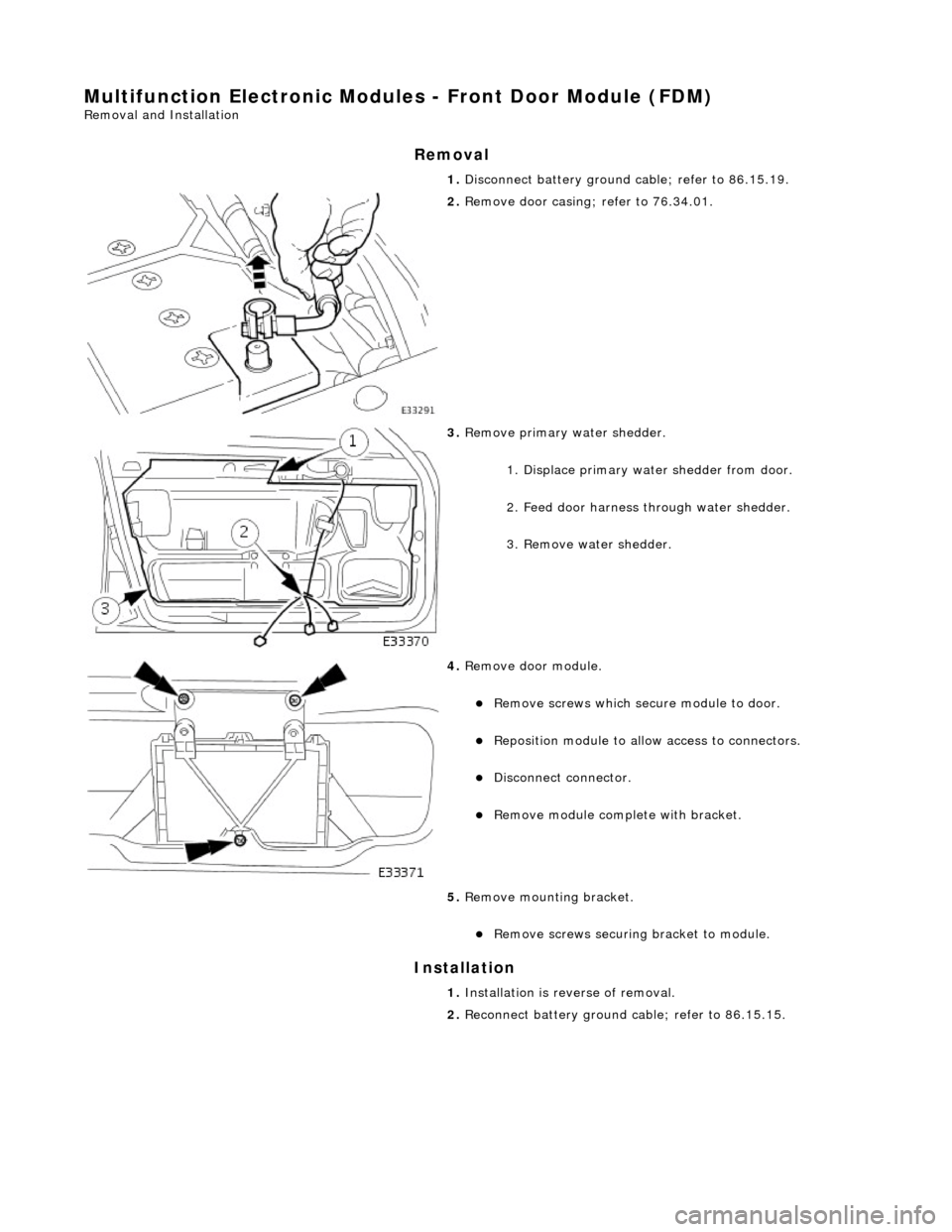
Multifunction Electronic Modules - Front Door Module (FDM)
Removal and Installation
Removal
Installation
1.
Disconnect battery ground cable; refer to 86.15.19.
2. Remove door casing; refer to 76.34.01.
3. Remove primary water shedder.
1. Displace primary water shedder from door.
2. Feed door harness through water shedder.
3. Remove water shedder.
4. Remove door module.
Remove screws which secu re module to door.
Reposition module to allow access to connectors.
Disconnect connector.
Remove module complete with bracket.
5. Remove mounting bracket.
Remove screws securing bracket to module.
1. Installation is reverse of removal.
2. Reconnect battery ground cable; refer to 86.15.15.
Page 2018 of 2490

Multifunction Electronic Modules - Rear Door Module (RDM)
Removal and Installation
Removal
Installation
1. Disconnect battery ground cable; refer to 86.15.19.
2. Remove door casing; refer to 76.34.04.
3. Remove primary water shedder.
1. Displace primary water shedder from door.
2. Feed door harness through water shedder.
3. Remove water shedder.
4. Remove door module.
Remove screws which secu re module to door.
Reposition module to allow access to connectors.
Disconnect connectors.
1. Installation is reverse of removal.
2. Reconnect battery ground cable; refer to 86.15.15.
Page 2019 of 2490
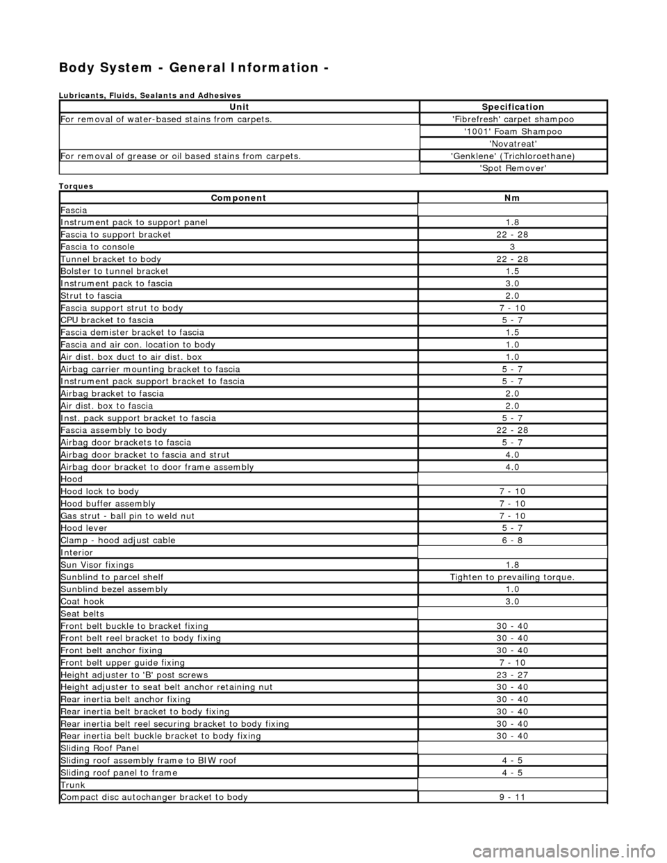
Body System - General Information -
Lubricants, Fluids, Sealants and Adhesives
Torques
UnitSpecification
For removal of water-based stains from carpets.'Fibrefresh' carpet shampoo
'1001' Foam Shampoo
'Novatreat'
For removal of grease or oil based stains from carpets.'Genklene' (Trichloroethane)
'Spot Remover'
ComponentNm
Fascia
Instrument pack to support panel1.8
Fascia to support bracket22 - 28
Fascia to console3
Tunnel bracket to body22 - 28
Bolster to tunnel bracket1.5
Instrument pack to fascia3.0
Strut to fascia2.0
Fascia support strut to body7 - 10
CPU bracket to fascia5 - 7
Fascia demister bracket to fascia1.5
Fascia and air con. location to body1.0
Air dist. box duct to air dist. box1.0
Airbag carrier mounting bracket to fascia5 - 7
Instrument pack suppo rt bracket to fascia5 - 7
Airbag bracket to fascia2.0
Air dist. box to fascia2.0
Inst. pack support bracket to fascia5 - 7
Fascia assembly to body22 - 28
Airbag door brackets to fascia5 - 7
Airbag door bracket to fascia and strut4.0
Airbag door bracket to door frame assembly4.0
Hood
Hood lock to body7 - 10
Hood buffer assembly7 - 10
Gas strut - ball pin to weld nut7 - 10
Hood lever5 - 7
Clamp - hood adjust cable6 - 8
Interior
Sun Visor fixings1.8
Sunblind to parcel shelfTighten to prevailing torque.
Sunblind bezel assembly1.0
Coat hook3.0
Seat belts
Front belt buckle to bracket fixing30 - 40
Front belt reel bracket to body fixing30 - 40
Front belt anchor fixing30 - 40
Front belt upper guide fixing7 - 10
Height adjuster to 'B' post screws23 - 27
Height adjuster to seat belt anchor retaining nut30 - 40
Rear inertia belt anchor fixing30 - 40
Rear inertia belt bracket to body fixing30 - 40
Rear inertia belt reel secu ring bracket to body fixing30 - 40
Rear inertia belt buckle bracket to body fixing30 - 40
Sliding Roof Panel
Sliding roof assembly frame to BIW roof4 - 5
Sliding roof panel to frame4 - 5
Trunk
Compact disc autochanger bracket to body9 - 11
Page 2038 of 2490
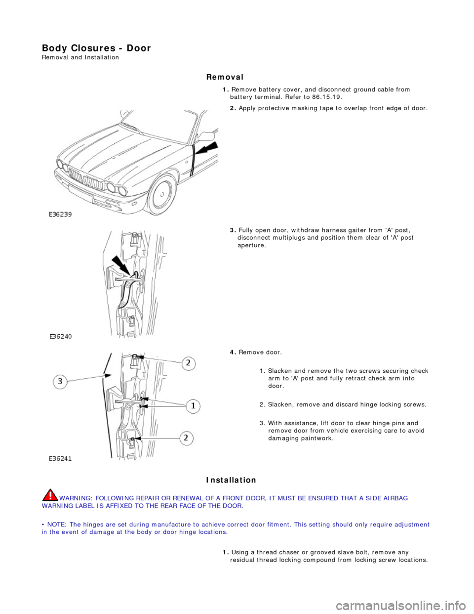
Body Closures - Door
Removal and Installation
Removal
Installation
WARNING: FOLLOWING REPAIR OR RENEWAL OF A FRONT DOOR, IT MUST BE ENSURED THAT A SIDE AIRBAG
WARNING LABEL IS AFFIXED TO THE REAR FACE OF THE DOOR.
• NOTE: The hinges are set during manufacture to achieve correct door fitment. This setting should on ly require adjustment
in the event of damage at the body or door hinge locations. 1.
Remove battery cover, and di sconnect ground cable from
battery terminal. Refer to 86.15.19.
2. Apply protective masking tape to overlap front edge of door.
3. Fully open door, withdraw harness gaiter from 'A' post,
disconnect multiplugs and posi tion them clear of 'A' post
aperture.
4. Remove door.
1. Slacken and remove the two screws securing check
arm to 'A' post and fully retract check arm into
door.
2. Slacken, remove and di scard hinge locking screws.
3. With assistance, lift d oor to clear hinge pins and
remove door from vehicle exercising care to avoid
damaging paintwork.
1. Using a thread chaser or gr ooved slave bolt, remove any
residual thread locking compound from locking screw locations.
Page 2039 of 2490
2.
Ensure that multiplugs are clea r of door front edge, and check
arm is fully retracted, then with assistance, lift door into
position and locate hinge pins.
3. Fit and fully tighten new hinge locking screws.
4. Position check arm bracket on 'A' post and fit and tighten
securing screws.
5. Fully open door and apply a thin co at of grease to both sides of
check arm.
6. Connect door harness multiplugs and fit and fully seat harness
gaiter in 'A' post.
7. Remove masking tape from front edge of door.
8. Check that door shuts correctly.
9. Wipe any excess grease from check arm.
10. Connect ground cable to batt ery terminal and fit battery
cover. Refer to 86.15.15.
Page 2040 of 2490
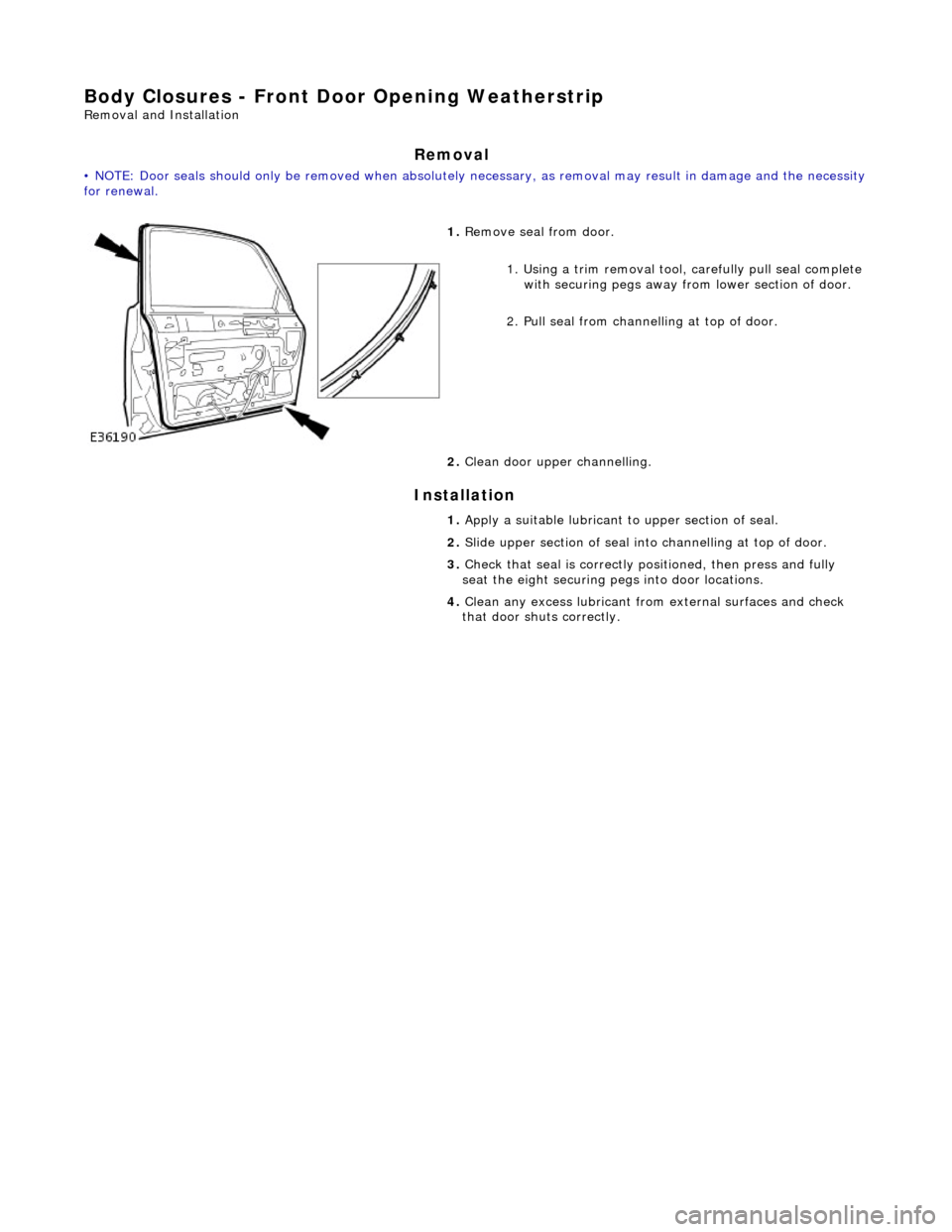
Body Closures - Front Door Opening Weatherstrip
Removal and Installation
Removal
• NOTE: Door seals should only be remove d when absolutely necessary, as removal may result in damage and the necessity for renewal.
Installation
1. Remove seal from door.
1. Using a trim removal tool, carefully pull seal complete
with securing pegs away from lower section of door.
2. Pull seal from chan nelling at top of door.
2. Clean door uppe r channelling.
1. Apply a suitable lubricant to upper section of seal.
2. Slide upper section of seal into channelling at top of door.
3. Check that seal is correctly positioned, then press and fully
seat the eight securing pegs into door locations.
4. Clean any excess lubricant from external surfaces and check
that door shuts correctly.
Page 2041 of 2490
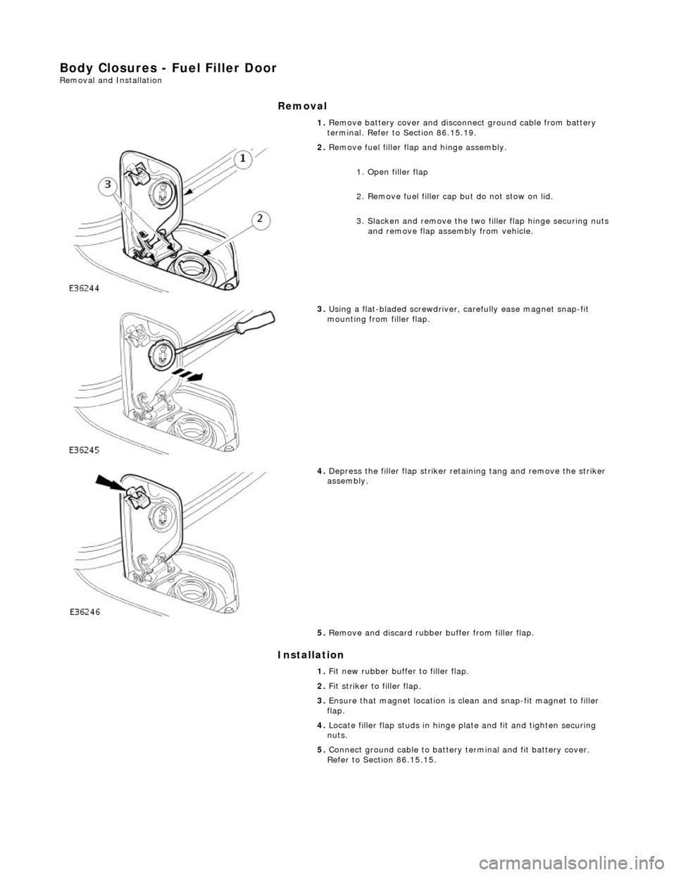
Body Closures - Fuel Filler Door Removal and Installation
Removal
Installation
1.
Remove battery cover and disconnect ground cable from battery
terminal. Refer to Section 86.15.19.
2. Remove fuel filler flap and hinge assembly.
1. Open filler flap
2. Remove fuel filler cap but do not stow on lid.
3. Slacken and remove the two filler flap hinge securing nuts and remove flap assembly from vehicle.
3. Using a flat-bladed screwdriver, carefully ease magnet snap-fit
mounting from filler flap.
4. Depress the filler flap striker retaining tang and remove the striker
assembly.
5. Remove and discard rubber buffer from filler flap.
1. Fit new rubber buffer to filler flap.
2. Fit striker to filler flap.
3. Ensure that magnet location is clean and snap-fit magnet to filler
flap.
4. Locate filler flap studs in hinge plate and fit and tighten securing
nuts.
5. Connect ground cable to battery terminal and fit battery cover.
Refer to Section 86.15.15.