Door remove JAGUAR X308 1998 2.G Workshop Manual
[x] Cancel search | Manufacturer: JAGUAR, Model Year: 1998, Model line: X308, Model: JAGUAR X308 1998 2.GPages: 2490, PDF Size: 69.81 MB
Page 717 of 2490
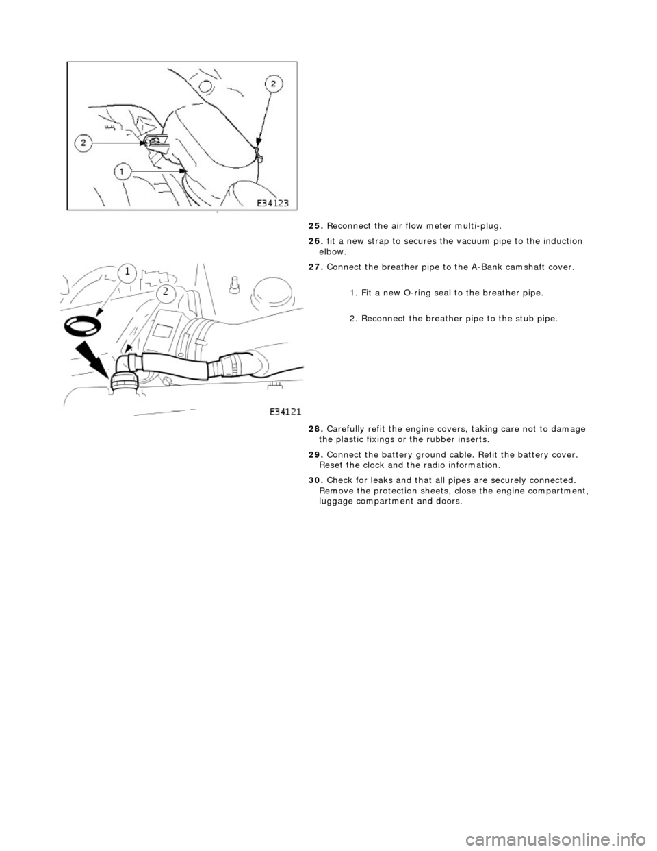
25. Reconnect the air flow meter multi-plug.
26. fit a new strap to secures the vacuum pipe to the induction
elbow.
27. Connect the breather pipe to the A-Bank camshaft cover.
1. Fit a new O-ring seal to the breather pipe.
2. Reconnect the breather pipe to the stub pipe.
28. Carefully refit the engine covers, taking care not to damage
the plastic fixings or the rubber inserts.
29. Connect the battery ground cabl e. Refit the battery cover.
Reset the clock and the radio information.
30. Check for leaks and that all pi pes are securely connected.
Remove the protection sheets, close the engine compartment,
luggage compartment and doors.
Page 728 of 2490
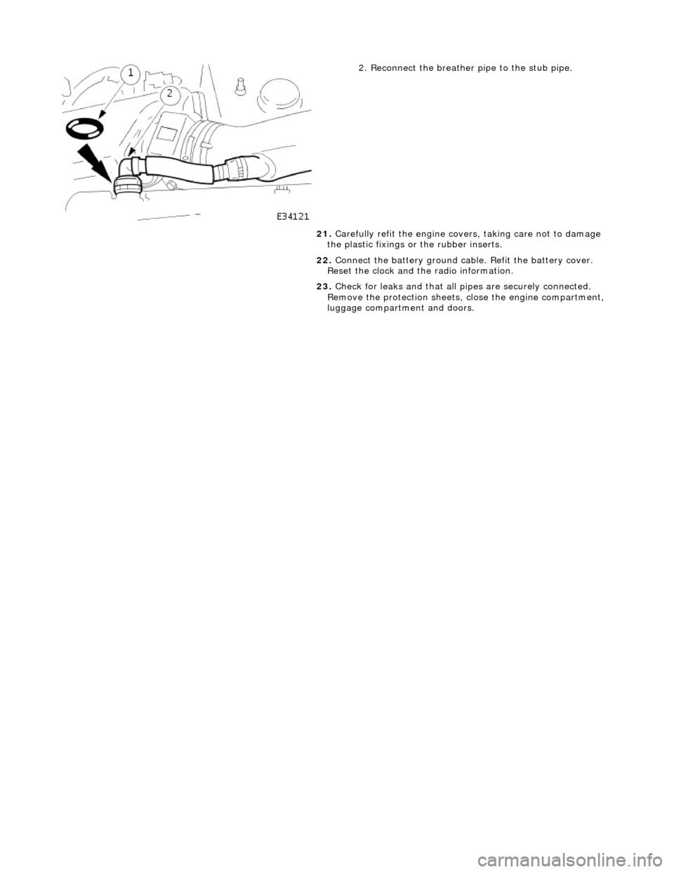
2. Reconnect the breather pipe to the stub pipe.
21. Carefully refit the engine covers, taking care not to damage
the plastic fixings or the rubber inserts.
22. Connect the battery ground cabl e. Refit the battery cover.
Reset the clock and the radio information.
23. Check for leaks and that all pi pes are securely connected.
Remove the protection sheets, close the engine compartment,
luggage compartment and doors.
Page 1693 of 2490

Filler Cap and P
ipe
The fuel
filler cap with bayonet-type fixi
ng is located beneath a remote-release sp ring-latched lid on the rear saddle panel
on the left-hand-side of the vehicle.
Fuel Pum
p
The fu
el pump(s) is energized by an ECM co
ntrolled relay. Fuel is drawn by this pu mp and supplied to the fuel injectors via
the fuel line, filter and fuel rails.
Servicing of the fuel pump re quires fuel tank removal.
Ev
aporative Loss Flange Assembly
The evaporative-loss flan
ge asse
mbly is mounted centrally on top of the tank. The flange assembly consists of a removeable
steel cap which mounts the evaporative emissions system vapor outlet valves and, if applicable, a pressure sensor. The
external electrical supply to th e fuel pump(s) is also made via a connector on the flange.
The flange assembly is fixed to the tank by a locking ring which is turned usin g special tool JD-174. A seal is fitted between
the flange assembly and the tank. Three di fferent flange assemblies are applicable according to the evaporative emission
system fitted to the vehicle. The fl ange size and fixing are identical fo r the three systems, as described.
Removal of the evaporative flange assembly is necessary to gain access to th e fuel pump(s) and other internal components.
To remove the evaporative fl ange assembly the fuel tank must first be removed.
The evaporative flange variant assemblies are described, together with service information, in Section 303-13.
Fuel R
eturn
Excess fuel
is directed back to
the fuel tank via a return line.
Fuel Pum
p Relay
The
fuel pump relay,
under control of the ECM, switches power to the fuel pump motor.
I
nertia Fuel Shutoff (IFS) Switch
The IF
S switch is located in the right-hand
side footwell behind the footboard carpet . When activated the switch isolates the
ignition system and fuel pump, releases any locked doors and disables unnecessary electrical systems. The system can be
reset by pressing down the flexible cover on the top of the switch.
• NOTE: The doors will not unlock if the IFS switch is tripped when the ignition switch is in position '0'.
Page 1777 of 2490
Air Distribution and Filtering - Center Registers
Removal and Installation
Removal
Installation
1.
Remove battery cover and disconnect ground cable from battery
terminal. Refer to 86.15.19.
2. Remove passenger airbag deployment door for access. Refer to
Section 501-20.
3. Remove major gauge module veneer panel for access. Refer to
76.47.24.
4. Carefully withdraw fascia centre veneer panel.
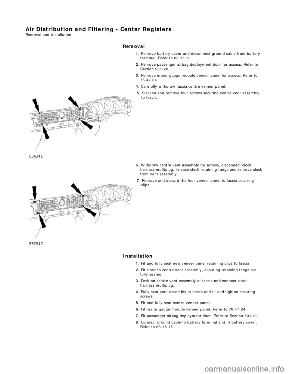
5. Slacken and remove four screws securing centre vent assembly
to fascia.
6. Withdraw centre vent assembly for access, disconnect clock
harness multiplug, release clock retaining tangs and remove clock
from vent assembly.
7. Remove and discard the four veneer panel to fascia securing
clips.
1. Fit and fully seat new veneer panel retaining clips to fascia.
2. Fit clock to centre vent assemb ly, ensuring retaining tangs are
fully seated.
3. Position centre vent assembly at fascia and connect clock
harness multiplug.
4. Fully seat vent assembly in fascia and fit and tighten securing
screws.
5. Fit and fully seat centre veneer panel.
6. Fit major gauge module veneer panel. Refer to 76.47.24.
7. Fit passenger airbag deployment door. Refer to Section 501-20.
8. Connect ground cable to battery terminal and fit battery cover.
Refer to 86.15.15.
Page 1842 of 2490
Control Components - Cold Air Bypass Blend Door Actuator
Removal and Installation
Removal
Installation
1.
Remove instrument panel for access; refer to 76.46.01.
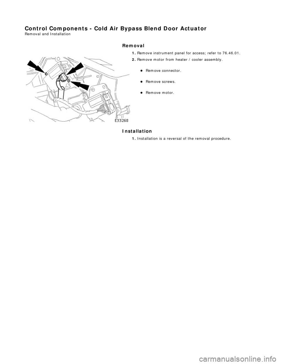
2. Remove motor from heater / cooler assembly.
Remove connector.
Remove screws.
Remove motor.
1. Installation is a reversal of the removal procedure.
Page 1843 of 2490
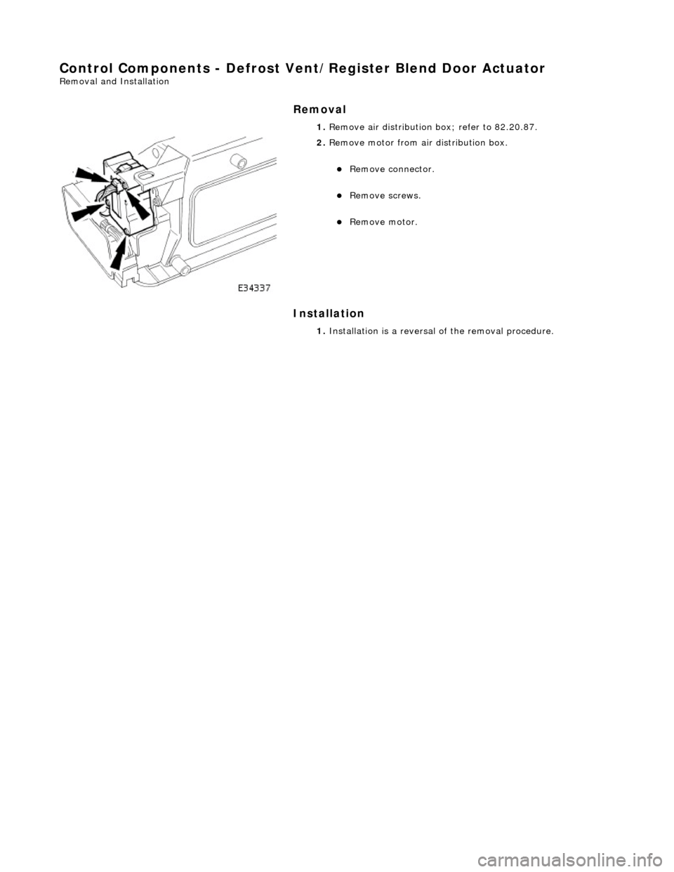
Control Components - Defrost Vent/Register Blend Door Actuator
Removal and Installation
Removal
Installation
1.
Remove air distribution box; refer to 82.20.87.
2. Remove motor from air distribution box.
Remove connector.
Remove screws.
Remove motor.
1. Installation is a reversal of the removal procedure.
Page 1844 of 2490
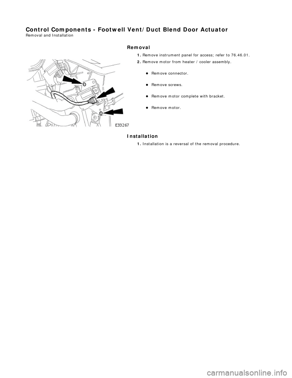
Control Components - Footwell Vent/Duct Blend Door Actuator
Removal and Installation
Removal
Installation
1.
Remove instrument panel for access; refer to 76.46.01.
2. Remove motor from heater / cooler assembly.
Remove connector.
Remove screws.
Remove motor complete with bracket.
Remove motor.
1. Installation is a reversal of the removal procedure.
Page 1845 of 2490
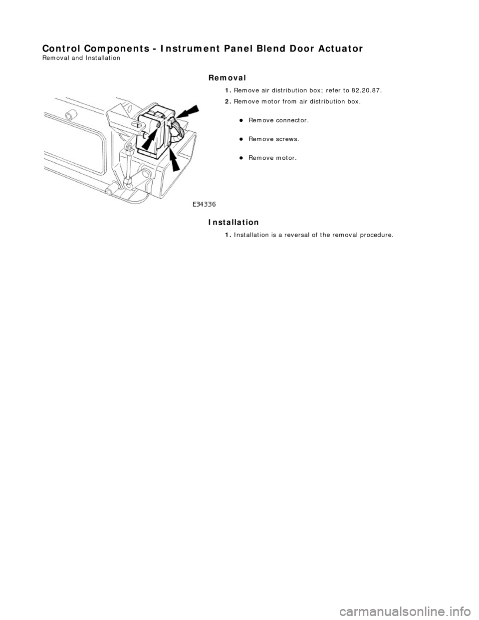
Control Components - Instrument Panel Blend Door Actuator
Removal and Installation
Removal
Installation
1.
Remove air distribution box; refer to 82.20.87.
2. Remove motor from air distribution box.
Remove connector.
Remove screws.
Remove motor.
1. Installation is a reversal of the removal procedure.
Page 1914 of 2490
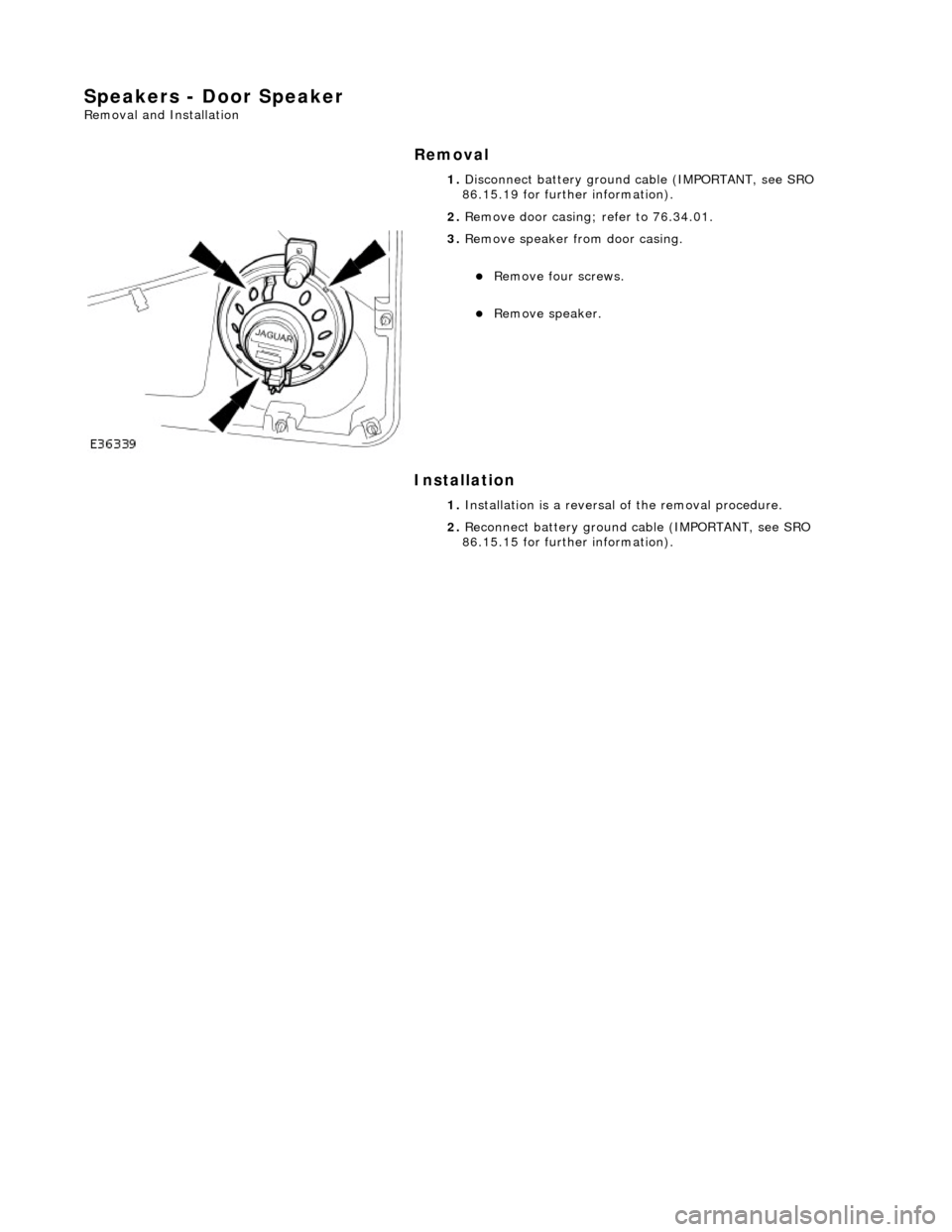
Speakers - Door Speaker
Removal and Installation
Removal
Installation
1.
Disconnect battery ground cable (IMPORTANT, see SRO
86.15.19 for further information).
2. Remove door casing; refer to 76.34.01.
3. Remove speaker from door casing.
Remove four screws.
Remove speaker.
1. Installation is a reversal of the removal procedure.
2. Reconnect battery ground cable (IMPORTANT, see SRO
86.15.15 for further information).
Page 1915 of 2490
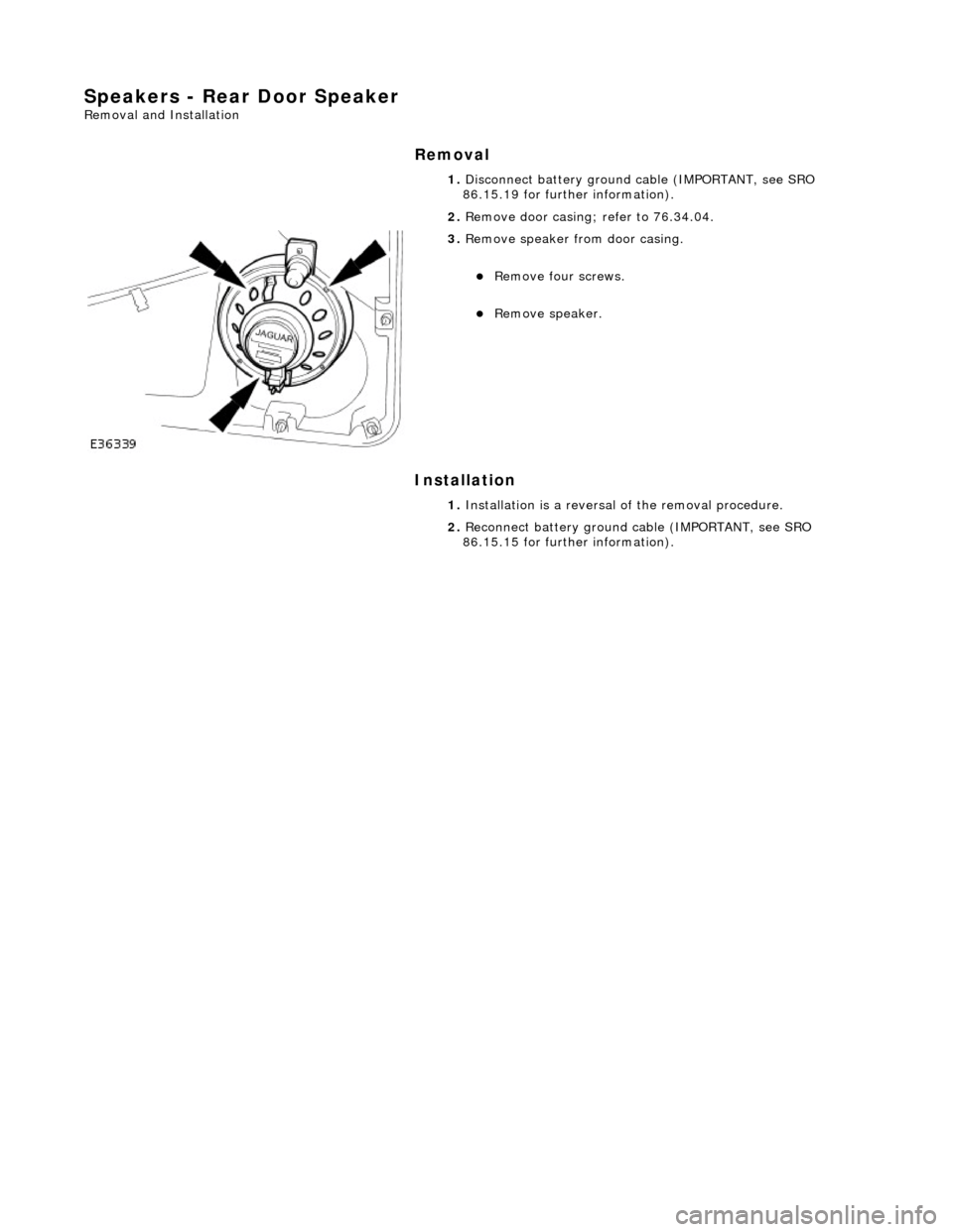
Speakers - Rear Door Speaker
Removal and Installation
Removal
Installation
1.
Disconnect battery ground cable (IMPORTANT, see SRO
86.15.19 for further information).
2. Remove door casing; refer to 76.34.04.
3. Remove speaker from door casing.
Remove four screws.
Remove speaker.
1. Installation is a reversal of the removal procedure.
2. Reconnect battery ground cable (IMPORTANT, see SRO
86.15.15 for further information).