Door remove JAGUAR X308 1998 2.G Service Manual
[x] Cancel search | Manufacturer: JAGUAR, Model Year: 1998, Model line: X308, Model: JAGUAR X308 1998 2.GPages: 2490, PDF Size: 69.81 MB
Page 2100 of 2490

Exterior Trim and Ornamentation - A-Pillar Moulding LH
Removal and Installation
Removal
Installation
1.
Remove front and rear grab handles. Refer to 76.58.30
2. Remove draught welt from adjace nt section of door aperture
flange.
3. Using a trim removal tool, carefu lly ease the six trim pad fir
tree fasteners from cantrail an d upper'A' post locations.
4. If premium ICE is fitt ed, carefully withdraw trim pad for access
and disconnect tweeter connectors.
5. Remove trim pad from vehicle an d remove tweeter. Refer to
415-03.
6. Remove and discard fir tree fasteners.
1. Fit new fir tree fasten ers to the trim pad.
2. Fit tweeter to trim pad. Refer to Section 415.
3. Position trim pad for access and connect tweeter to harness.
4. Commencing at top of 'A' post and working rearwards, fully
seat three fir tree fasteners.
5. Fully seat remaining three fir tr ee fasteners in upper'A' post.
6. Fit front and rear combined gr ab handles. Refer to 76.58.30
7. Fit draught welt to adjacent section of door aperture flange.
Page 2101 of 2490

Exterior Trim and Ornamentation - A-Pillar Moulding RH
Removal and Installation
Removal
Installation
1.
Remove rear grab handle. Refer to 76.58.30.
2. Remove draught welt from adjace nt section of door aperture
flange.
3. Using a trim removal tool, carefu lly ease the six trim pad fir
tree fasteners from cantrail an d upper'A' post locations.
4. If premium ICE is fitt ed, carefully withdraw trim pad for access
and disconnect tweeter connectors.
5. Remove trim pad from vehicle an d remove tweeter. Refer to
415-03.
6. Remove and discard fir tree fasteners.
1. Fit new fir tree fasten ers to the trim pad.
2. Fit tweeter to trim pad. Refer to Section 415.
3. Position trim pad for access and connect tweeter to harness.
4. Commencing at top of 'A' post and working rearwards, fully
seat three fir tree fasteners.
5. Fully seat remaining three fir tr ee fasteners in upper'A' post.
6. Fit grab handle. Refer to 76.58.30.
7. Fit draught welt to adjacent section of door aperture flange.
Page 2103 of 2490

Exterior Trim and Ornamentation - Door Moulding
Removal and Installation
Removal
Installation
1.
Apply suitable protecti ve tape to immediately adjacent areas of
paintwork.
2. Using a hand-held heat gun, appply heat uniformly along
moulding length.
3. Applying local heat at one end and using a suitable thin lever
to avoid damaging paintwork, progressively ease moulding
away from door panel.
4. Discard moulding and remove protective tape.
5. Remove any residual adhesive and thoroughly clean area using
white spirit.
1. NOTE: Optimum adhesion is achi eved by warming body panel
and moulding to 65deg C.
Using white spirit ensure that mounting area is clean, dry and
de-greased.
2. Remove protective backing tape from moulding.
3. NOTE: Do not allow moulding to contact the body panel until it
is correctly aligned.
Heat moulding and moun ting area to 65degC.)
4. Aligning with adjacent mouldings or to match opposite side of
vehicle, press new moulding firmly onto body panel.
5. Apply hand pressure along moulding length to ensure
satisfactory adhesion.
6. Allow moulding and door panel to cool , then thoroughly clean
both using white spirit.
7. Apply a coat of suitab le polish to moulding and body panel.
Page 2114 of 2490
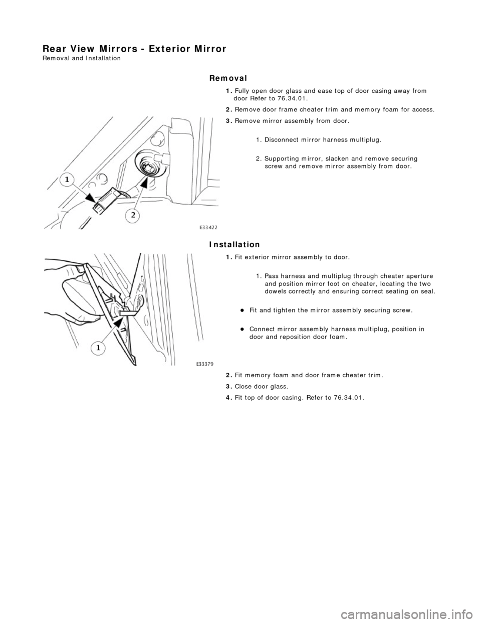
Rear View Mirrors - Exterior Mirror
Removal and Installation
Removal
Installation
1.
Fully open door glass and ease top of door casing away from
door Refer to 76.34.01.
2. Remove door frame cheater trim and memory foam for access.
3. Remove mirror assembly from door.
1. Disconnect mirror harness multiplug.
2. Supporting mirror, slacken and remove securing screw and remove mirror assembly from door.
1. Fit exterior mirror assembly to door.
1. Pass harness and multiplu g through cheater aperture
and position mirror foot on cheater, locating the two
dowels correctly and ensuring correct seating on seal.
Fit and tighten the mirror assembly securing screw.
Connect mirror assembly harness multiplug, position in
door and reposition door foam.
2. Fit memory foam and door frame cheater trim.
3. Close door glass.
4. Fit top of door casing. Refer to 76.34.01.
Page 2157 of 2490
Installation
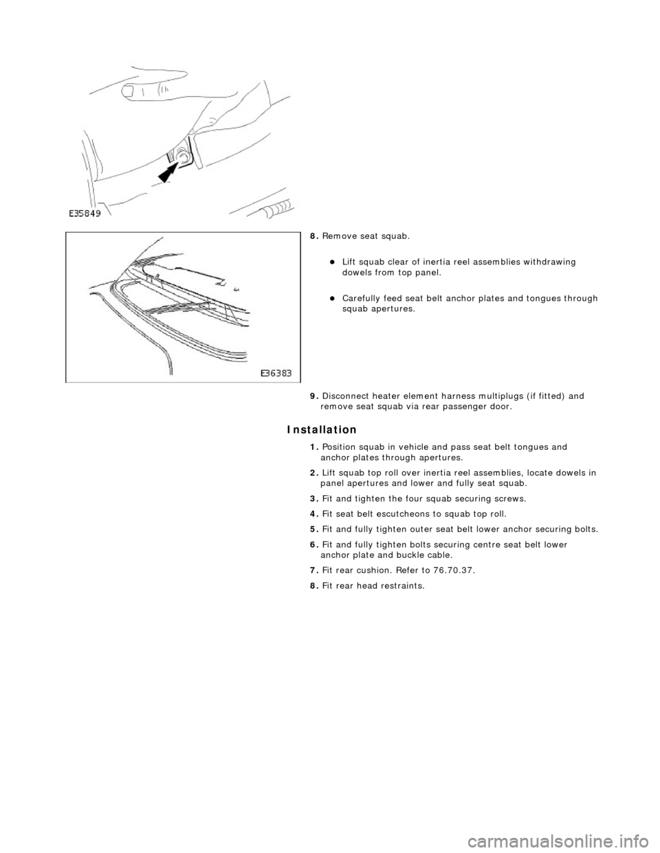
8. Remove seat squab.
Lift squab clear of inertia reel assemblies withdrawing
dowels from top panel.
Carefully feed seat belt anch or plates and tongues through squab apertures.
9. Disconnect heater element harness multiplugs (if fitted) and
remove seat squab via rear passenger door.
1. Position squab in vehicle and pass seat belt tongues and
anchor plates through apertures.
2. Lift squab top roll over inertia reel assemblies, locate dowels in
panel apertures and lower and fully seat squab.
3. Fit and tighten the four squab securing screws.
4. Fit seat belt escutcheons to squab top roll.
5. Fit and fully tighten outer seat be lt lower anchor securing bolts.
6. Fit and fully tighten bolts securing centre seat belt lower
anchor plate and buckle cable.
7. Fit rear cushion. Refer to 76.70.37.
8. Fit rear head restraints.
Page 2181 of 2490

Glass, Frames and Mechanisms - Door Window Control Switch Bulb
Removal and Installation
Removal
1. Remove casing/armrest asse mbly from door. Refer to
76.34.01.
2. Slacken and remove armres t front securing screw
3. Position armrest for access, slacken and remove two
switchpack securing screws and remove switchpack assembly from armrest.
4. Invert switchpack and using a small flat bladed screwdriver
rotate bulb holder 1/8 turn counterclockwise.
5. Remove bulb from switchpack base.
Page 2183 of 2490
Glass, Frames and Mechanisms - Front Door Window Glass
Removal and Installation
Removal
Installation
1. Remove battery cover and disc onnect ground cable from
battery terminal. Refer to 86.15.19.
2. Remove front door casing. Refer to 76.34.01.
3. Remove water shedder carefu lly guiding harness through
penetration, and place adhesive face down on clean polythene
sheet.
4. Position PVC weathe rshield for access.
5. Remove front door modu le. Refer to 86.80.34.
6. Remove front door glass lift motor and regulator assembly.
Refer to 86.25.04.
7. Supporting glass, remove tape securing it to top of door for
motor removal.
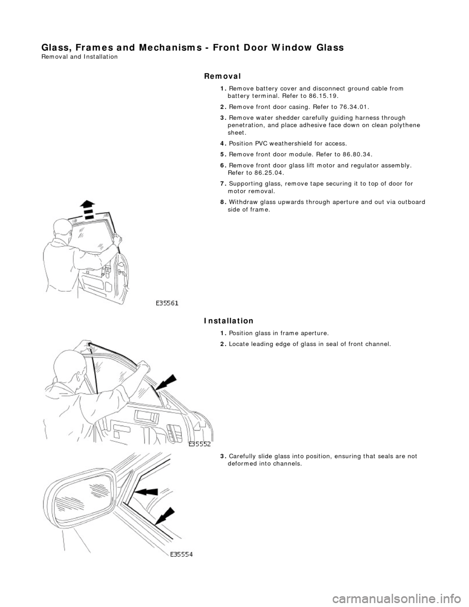
8. Withdraw glass upwards through aperture and out via outboard side of frame.
1. Position glass in frame aperture.
2. Locate leading edge of glass in seal of front channel.
3. Carefully slide glass into position, ensuring that seals are not
deformed into channels.
Page 2185 of 2490
Glass, Frames and Mechanisms - Front Door Window Glass Weatherstrip
Removal and Installation
Removal
Installation
1.
Pull seal out of door frame channelling and discard seal.
2. Clean channelling ensuring that any residual adhesive is
removed.
1. Avoiding adhesive at ends, apply a suitable dry lubricant to
seal.
2. Commencing at front of frame, feed seal into channelling
ensuring it is uniformly tensioned and free from kinks.
3. Wipe residual lubricant fro m adhesive contact areas.
4. Remove protective tape from en ds and press adhesive firmly
onto frame.
5. Clean any excess lubricant from external surfaces and check
that door shuts correctly.
Page 2186 of 2490
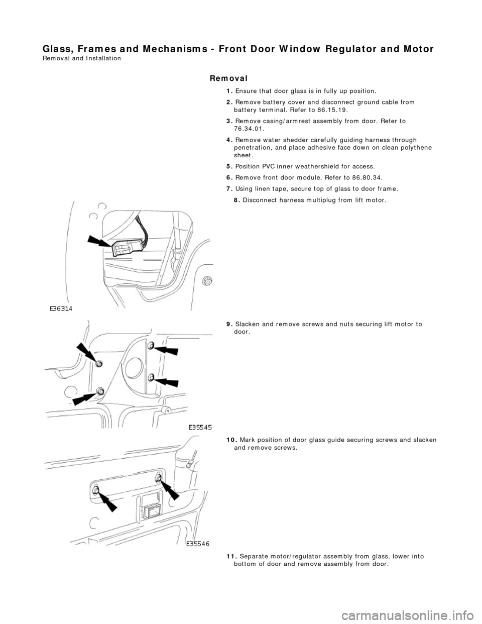
Glass, Frames and Mechanisms - Front Door Window Regulator and Motor
Removal and Installation
Removal
1. Ensure that door glass is in fully up position.
2. Remove battery cover and disc onnect ground cable from
battery terminal. Refer to 86.15.19.
3. Remove casing/armrest asse mbly from door. Refer to
76.34.01.
4. Remove water shedder carefu lly guiding harness through
penetration, and place adhesive face down on clean polythene
sheet.
5. Position PVC inner weat hershield for access.
6. Remove front door modu le. Refer to 86.80.34.
7. Using linen tape, secure to p of glass to door frame.
8. Disconnect harness mult iplug from lift motor.
9. Slacken and remove screws and nuts securing lift motor to
door.
10. Mark position of door glass gu ide securing screws and slacken and remove screws.
11. Separate motor/regulator assembly from glass, lower into
bottom of door and remove assembly from door.
Page 2187 of 2490
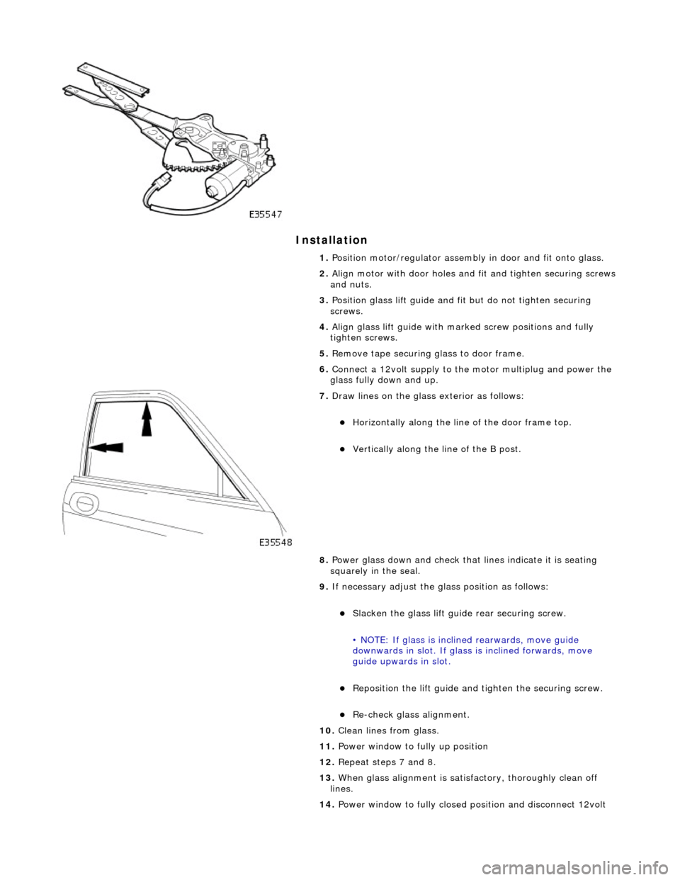
Installation
1. Position motor/regulator assembly in door and fit onto glass.
2. Align motor with door holes and fit and tighten securing screws
and nuts.
3. Position glass lift guide and fi t but do not tighten securing
screws.
4. Align glass lift guide with marked screw positions and fully
tighten screws.
5. Remove tape securing glass to door frame.
6. Connect a 12volt supply to the motor multiplug and power the
glass fully down and up.
7. Draw lines on the glass exterior as follows:
Horizontally along the line of the door frame top.
Vertically along the line of the B post.
8. Power glass down and check that lines indicate it is seating
squarely in the seal.
9. If necessary adjust the glass position as follows:
Slacken the glass lift guid e rear securing screw.
• NOTE: If glass is inclin ed rearwards, move guide
downwards in slot. If glass is inclined forwards, move
guide upwards in slot.
Reposition the lift guide and tighten the securing screw.
Re-check glass alignment.
10. Clean lines from glass.
11. Power window to fully up position
12. Repeat steps 7 and 8.
13. When glass alignment is satisf actory, thoroughly clean off
lines.
14. Power window to fully closed po sition and disconnect 12volt