Oxygen Sensor JAGUAR X308 1998 2.G User Guide
[x] Cancel search | Manufacturer: JAGUAR, Model Year: 1998, Model line: X308, Model: JAGUAR X308 1998 2.GPages: 2490, PDF Size: 69.81 MB
Page 1188 of 2490
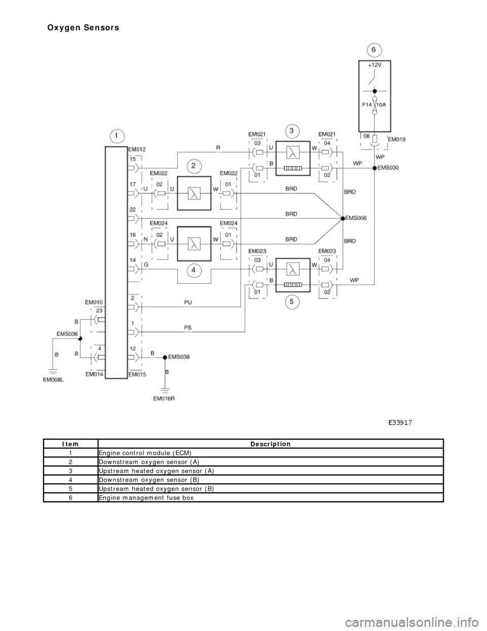
It e
m
De
scr
iption
1Engine
c
ontrol
module (ECM)
2Do
wnstream oxygen sensor (A)
3Upstream heated ox
ygen sensor
(A)
4D
o
wnstream oxygen sensor (B)
5Upstream heated ox
ygen sensor (B)
6Engine
management fuse box
Ox
yg
en Sensors
Page 1211 of 2490
Is
the resistance less than 10,000 ohms?
Yes REPAIR the short circuit. For addi tional information, refer to the wiring diagrams. CLEAR the DTC.
TEST the system for normal operation.
No GO to E4
.
E4
: CHECK THE H02S GROUND
CIRCUIT FOR OPEN CIRCUIT
Re
connect the ECM electrical connector, EM12.
1
Meas
ure the resistance between EM21, pin 04 (BRD) and GROUND.
2
Is th
e resistance greater than 5 ohms?
Yes
REPAIR the circuit (this is a braide d lead which would require different repair techniques to standard
wiring). For additional information, refer to the wiring diagrams. CL EAR the DTC. TEST the system for
normal operation.
No INSTALL a new H02S.
REFER to Heated Oxygen Sensor (HO2S) RH
in this section.
CLEAR the DTC. TEST the syst em for normal operation.
PI
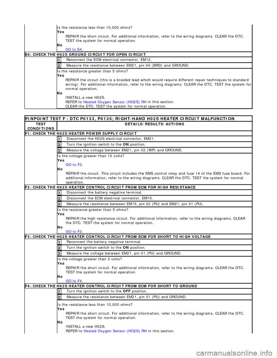
NPOINT TEST F : DTC P0133, P0135; RIGHT-HAND H02S HEATER CIRCUIT MALFUNCTION
TE
ST
CONDITIONS
D
ETAILS/RESULTS/ACTIONS
F1:
CHECK THE H02S HEATER POWER SUPPLY CIRCUIT
D
isconnect the H02S electrical connector, EM21.
1
Turn the ignition swi
tch to the ON
position.
2
Meas
ure the voltage between EM21, pin 02 (WP) and GROUND.
3
Is the vol
tage greater than 10 volts?
Yes GO to F2
.
No
REPAIR the circuit. This circuit in cludes the EMS control relay and fu se 14 of the EMS fuse board. For
additional information, refer to the wiring diagrams. CLEAR the DT C. TEST the system for normal
operation.
F2: CHECK THE H02
S HEATER CONTROL CI
RCUIT FROM ECM FOR HIGH RESISTANCE
Di
sconnect the battery negative terminal.
1
D
isconnect the ECM electrical connector, EM15.
2
Me
asure the resistance between EM15, pin 02 (PU) and EM21, pin 01 (PU).
3
Is th
e resistance greater than 5 ohms?
Yes REPAIR the high resistance circui t. For additional information, refer to the wiring diagrams. CLEAR
the DTC. TEST the system for normal operation.
No GO to F3
.
F3: CHECK THE H02
S HEATER CONTROL CIRCUI
T FROM ECM FOR SHORT TO HIGH VOLTAGE
R
econnect the battery negative terminal.
1
Turn the ignition swi
tch to the ON
position.
2
Meas
ure the voltage between EM21, pin 01 (PU) and GROUND.
3
Is th
e voltage greater than 3 volts?
Yes REPAIR the short circuit. For addi tional information, refer to the wiring diagrams. CLEAR the DTC.
TEST the system for normal operation.
No GO to F4
.
F4: CHECK THE H02
S HEATER CONTROL CI
RCUIT FROM ECM FOR SHORT TO GROUND
Turn the ignition swi
tch to the OFF
position.
1
Meas
ure the resistance between EM21, pin 01 (PU) and GROUND.
2
Is
the resistance less than 10,000 ohms?
Yes REPAIR the short circuit. For addi tional information, refer to the wiring diagrams. CLEAR the DTC.
TEST the system for normal operation.
No INSTALL a new H02S.
REFER to Heated Oxygen Sensor (HO2S) RH
in this section.
Page 1213 of 2490
Yes
REPAIR the high resistance circui t. For additional information, refer to the wiring diagrams. CLEAR
the DTC. TEST the system for normal operation.
No GO to H2
.
H
2: CHECK THE H02S SENSE CIRCUIT FOR SHORT TO HIGH VOLTAGE
R
econnect the battery negative terminal.
1
Turn the ignition swi
tch to the ON
position.
2
M
easure the voltage between EM12, pin 14 (G) and GROUND.
3
Is th
e voltage greater than 3 volts?
Yes REPAIR the short circuit. For addi tional information, refer to the wiring diagrams. CLEAR the DTC.
TEST the system for normal operation.
No GO to H3
.
H
3: CHECK THE H02S SENSE CIRCUIT FOR SHORT TO GROUND
Turn the ignition swi
tch to the OFF
position.
1
Meas
ure the resistance between EM12, pin 14 (G) and GROUND.
2
Is
the resistance less than 10,000 ohms?
Yes REPAIR the short circuit. For addi tional information, refer to the wiring diagrams. CLEAR the DTC.
TEST the system for normal operation.
No GO to H4
.
H4:
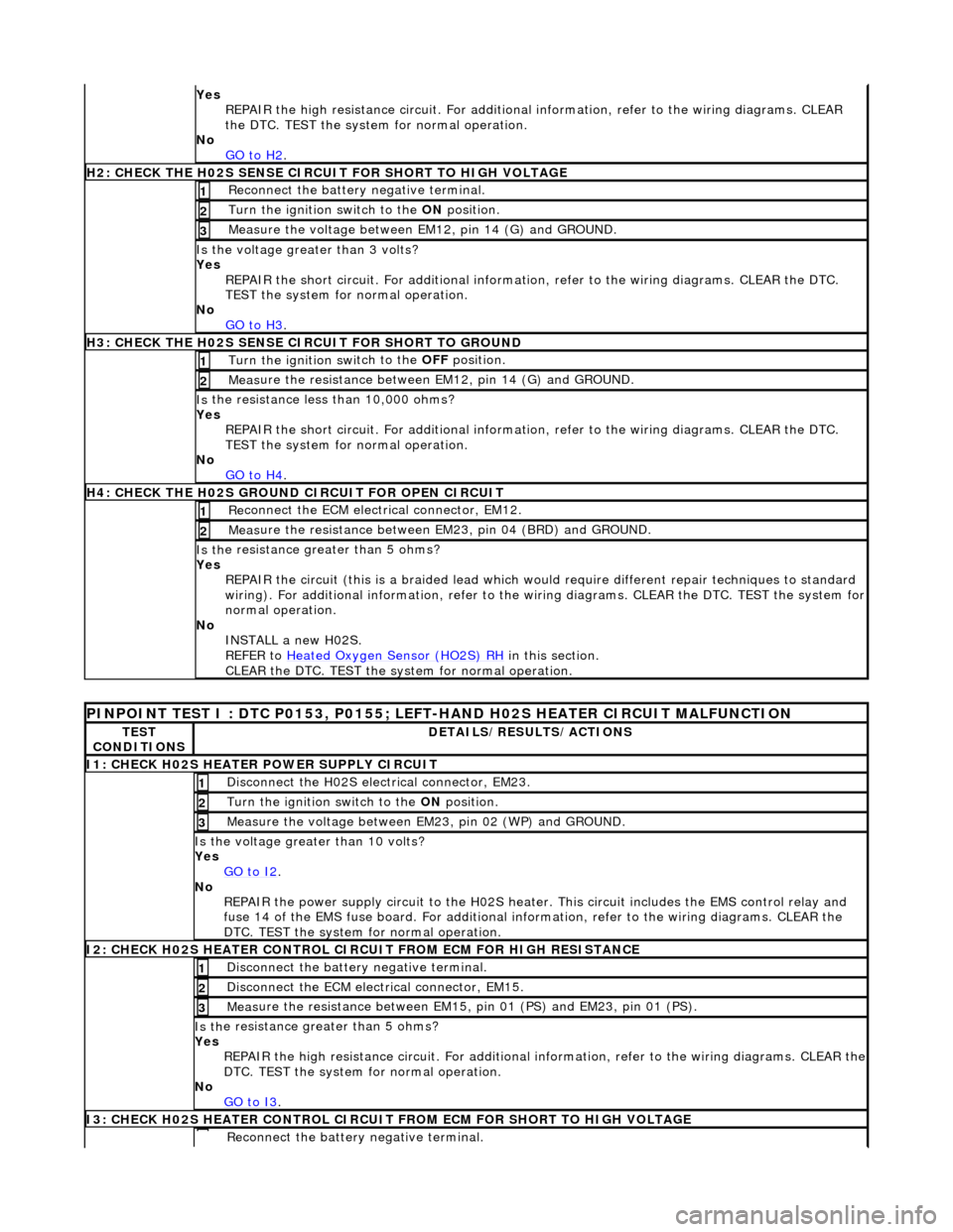
CHECK THE H02S GROUND CIRCUIT FOR OPEN CIRCUIT
Re
connect the ECM electrical connector, EM12.
1
Meas
ure the resistance between EM23, pin 04 (BRD) and GROUND.
2
Is th
e resistance greater than 5 ohms?
Yes REPAIR the circuit (this is a braide d lead which would require different repair techniques to standard
wiring). For additional information, refer to the wiring diagrams. CL EAR the DTC. TEST the system for
normal operation.
No INSTALL a new H02S.
REFER to Heated Oxygen Sensor (HO2S) RH
in this section.
CLEAR the DTC. TEST the syst em for normal operation.
P
INPOINT TEST I : DTC P0153, P0155; LEFT-HAND H02S HEATER CIRCUIT MALFUNCTION
TE
ST
CONDITIONS
D
ETAILS/RESULTS/ACTIONS
I
1: CHECK H02S HEATER POWER SUPPLY CIRCUIT
D
isconnect the H02S electrical connector, EM23.
1
Turn the ignition swi
tch to the
ON position.
2
Meas
ure the voltage between EM23, pin 02 (WP) and GROUND.
3
Is the vol
tage greater than 10 volts?
Yes GO to I2
.
No
REPAIR the power supply circuit to the H02S heater. This circuit includes the EMS control relay and
fuse 14 of the EMS fuse board. For additional info rmation, refer to the wiring diagrams. CLEAR the
DTC. TEST the system for normal operation.
I
2: CHECK H02S HEATER CONTROL CIRC
UIT FROM ECM FOR HIGH RESISTANCE
Di
sconnect the battery negative terminal.
1
D
isconnect the ECM electrical connector, EM15.
2
Meas
ure the resistance between EM15,
pin 01 (PS) and EM23, pin 01 (PS).
3
Is th
e resistance greater than 5 ohms?
Yes REPAIR the high resistance circuit. For additional information, refer to the wiring diagrams. CLEAR the
DTC. TEST the system for normal operation.
No GO to I3
.
I
3: CHECK H02S HEATER CONTROL CIRCUIT
FROM ECM FOR SHORT TO HIGH VOLTAGE
R
econnect the battery negative terminal.
Page 1214 of 2490

1
Turn the ignition swit
ch to the
ON position.
2
Meas ure t
he voltage between EM23, pin 01 (PS) and GROUND.
3
Is th
e volt
age greater than 3 volts?
Yes REPAIR the short circuit. For addi tional information, refer to the wiring diagrams. CLEAR the DTC.
TEST the system for normal operation.
No GO to I4
.
I4
: CHECK H02S HEATER CONTROL CIRCUIT FROM ECM FOR SHORT TO GROUND
Turn the ignition swit
ch to the
OFF position.
1
Measure t
he resistance between EM23, pin 01 (PS) and GROUND.
2
Is t
he resistance less than 10,000 ohms?
Yes REPAIR the short circuit. For addi tional information, refer to the wiring diagrams. CLEAR the DTC.
TEST the system for normal operation.
No INSTALL a new H02S.
REFER to Heated Oxygen Sensor (HO2S) LH
in this
section.
CLEAR the DTC. TEST the system for normal operation.
P INPOINT TES
T J : DTC P0157, P0158; LEFT-H
AND CATALYST MONITOR SENSOR LOW/HIGH
VOLTAGE, NO ACTIVITY
TE S
T
CONDITIONS
D E
TAILS/RESULTS/ACTIONS
J
1
: CHECK THE CATALYST MONITOR SENSOR
SENSE CIRCUIT FOR HIGH RESISTANCE
Disc
onnect the battery negative terminal.
1
Di
sc
onnect the catalyst monitor sensor electrical connector, EM24.
2
Disc
onne
ct the ECM electrical connector, EM12.
3
Meas
ure t
he resistance between EM24, pin 02 (N) and EM12, pin 16 (N).
4
Is th
e res
istance greater than 5 ohms?
Yes REPAIR the high resistance circui t. For additional information, refer to the wiring diagrams. CLEAR
the DTC. TEST the system for normal operation.
No GO to J2
.
J2
: CHECK THE CATALYST MONITOR SENSOR SENSE CIRCUIT FOR SHORT TO HIGH VOLTAGE
R
e
connect the battery negative terminal.
1
Turn the ignition swi
t
ch to the ON
position.
2
Measure t
he voltage between EM12, pin 16 (N) and GROUND.
3
Is th
e volt
age greater than 3 volts?
Yes REPAIR the short circuit. For addi tional information, refer to the wiring diagrams. CLEAR the DTC.
TEST the system for normal operation.
No GO to J3
.
J3
: CHECK THE CATALYST MONITOR SENSOR
SENSE CIRCUIT FOR SHORT TO GROUND
Turn the ignition swit
ch to the OFF
position.
1
Measure t
he resistance between EM12, pin 16 (N) and GROUND.
2
Is t
he resistance less than 10,000 ohms?
Yes REPAIR the short circuit. For addi tional information, refer to the wiring diagrams. CLEAR the DTC.
TEST the system for normal operation.
No GO to J4
.
J4
: CHECK THE CATALYST MONITOR SENSOR
GROUND CIRCUIT FOR OPEN CIRCUIT
Reconn
ect the ECM electrical connector, EM12.
1
Meas
ure t
he resistance between EM24, pin 01 (BRD) and GROUND.
2
Is th
e res
istance greater than 5 ohms?
Yes REPAIR the circuit (this is a braide d lead which would require different repair techniques to standard
wiring). For additional information, refer to the wiring diagrams. CL EAR the DTC. TEST the system for
Page 1249 of 2490
Electron
ic Engine Controls -
Heated Oxygen Sensor (HO2S) LH
Rem
oval and Installation
General Equipment
Remov
al
Installation
Snap
-on tool S6176
1. WARNING: ENSURE THAT TH E EXHAUST AND CATALYST
ARE COLD BEFORE COMMENCING WORK
Disconnect the battery ground lead.
2.
CAUTION: Make sure the wiring harness is not twisted or
damaged on removal. Failure to follow this instruction may result in
damage to the vehicle.
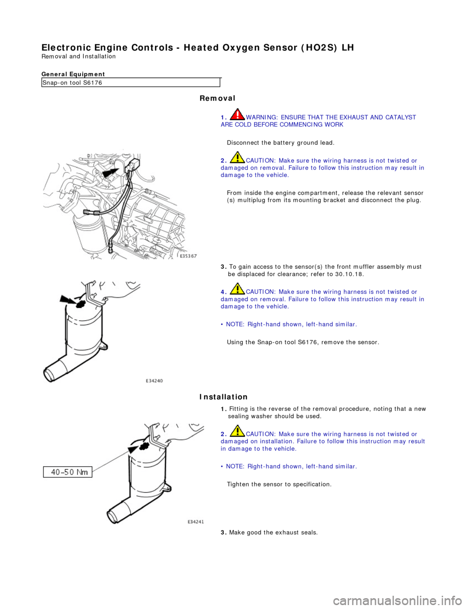
From inside the engine compartm ent, release the relevant sensor
(s) multiplug from its mounting bracket and disconnect the plug.
3.
To gain access to the sensor(s) the front muffler assembly must
be displaced for clearance; refer to 30.10.18.
4.
CAUTION: Make sure the wiring harness is not twisted or
damaged on removal. Failure to follow this instruction may result in
damage to the vehicle.
• NOTE: Right-hand shown, left-hand similar.
Using the Snap-on tool S6176, remove the sensor.
1.
Fitting is the reverse of the remo val procedure, noting that a new
sealing washer should be used.
2.
CAUTION: Make sure the wiring harness is not twisted or
damaged on installation. Failure to follow this instruction may result
in damage to the vehicle.
• NOTE: Right-hand shown, left-hand similar.
Tighten the sensor to specification.
3.
Make good the exhaust seals.
Page 1250 of 2490
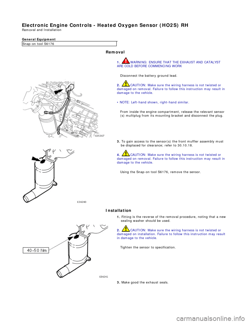
Electronic
Engine Controls -
Heated Oxygen Sensor (HO2S) RH
Remo
val and Installation
General Equipment
Remov a
l
Installation
Snap -on to
ol S6176
1. WARNING: ENSURE THAT TH E EXHAUST AND CATALYST
ARE COLD BEFORE COMMENCING WORK
Disconnect the battery ground lead.
2. CAU
TION: Make sure the wiring harness is not twisted or
damaged on removal. Failure to follow this instruction may result in
damage to the vehicle.
• NOTE: Left-hand shown, right-hand similar.
From inside the engine compartm ent, release the relevant sensor
(s) multiplug from its mounting bracket and disconnect the plug.
3. To
gain access to the sensor(s)
the front muffler assembly must
be displaced for clearance; refer to 30.10.18.
4. CAU
TION: Make sure the wiring harness is not twisted or
damaged on removal. Failure to follow this instruction may result in
damage to the vehicle.
Using the Snap-on tool S6176, remove the sensor.
1. Fittin
g is the reverse of the remo
val procedure, noting that a new
sealing washer should be used.
2. CAU
TION: Make sure the wiring harness is not twisted or
damaged on installation. Failure to follow this instruction may result
in damage to the vehicle.
Tighten the sensor to specification.
3. M
ake good the exhaust seals.
Page 1522 of 2490

Exhaust System -
Torques
ComponentNm
Nut - Downpipe catalytic converter to exhaust manifold14 - 18
Bolt - Downpipe catalytic converter to lower mounting bracket39 - 51
Bolt - Front muffler mounting to gearbox (SC)22 - 28
Bolt - Front muffler mounting to front muffler cross brace (SC)22 - 28
Bolt - Over-axle mounting to rear suspension A-frame22 - 28
Torca clamps52 - 68
Oxygen sensor to downpipe40 - 50
Page 1525 of 2490
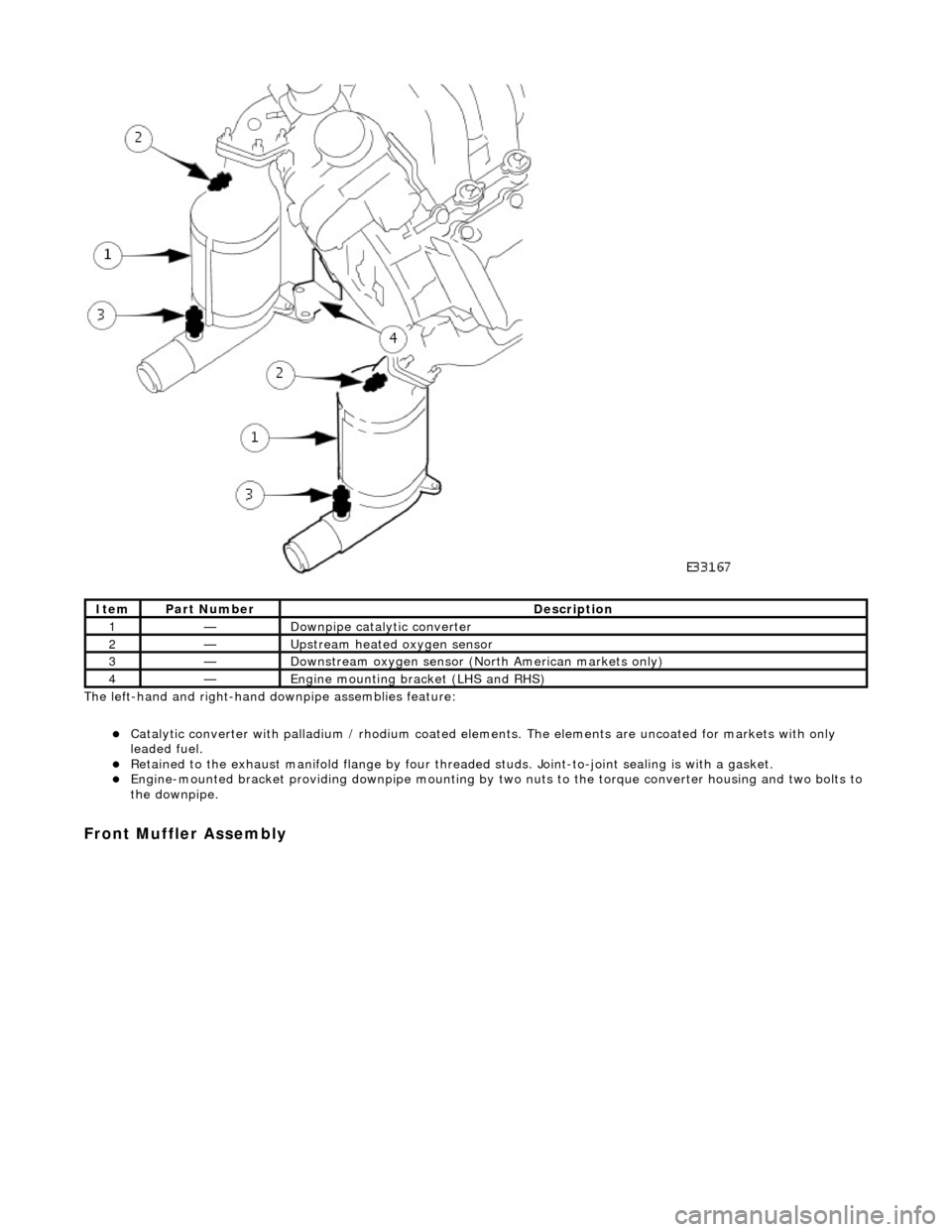
The left-hand and right-hand do wnpipe assemblies feature:
Catalytic converter with palladium / rhodium coated elem ents. The elements are uncoated for markets with only
leaded fuel.
Retained to the exhaust manifold flange by four thread ed studs. Joint-to-joint sealing is with a gasket. Engine-mounted bracket providing downpipe mounting by two nuts to the torque converter housing and two bolts to
the downpipe.
Front Muffler Assembly
ItemPart NumberDescription
1—Downpipe catalytic converter
2—Upstream heated oxygen sensor
3—Downstream oxygen sensor (North American markets only)
4—Engine mounting bracket (LHS and RHS)
Page 1528 of 2490

Joints and Clamps
Pipe-to-pipe joints which are slip joints, feature:
Clamping by Torca strap clamp. Indicator rings providing Maximum, Mini mum and Nominal engagement marks.
Oxygen Sensor (O2)
Location
Page 1529 of 2490

Parts List
Operation
ItemPart NumberDescription
1—Heated oxygen sensor (upstream)
2—Oxygen sensor (downstream)
3—Catalytic converter