Power steering pump JAGUAR X308 1998 2.G User Guide
[x] Cancel search | Manufacturer: JAGUAR, Model Year: 1998, Model line: X308, Model: JAGUAR X308 1998 2.GPages: 2490, PDF Size: 69.81 MB
Page 468 of 2490
Hiss (Swish)
Hiss or Val
ve Hiss is a high-frequency so
und coming from the steering gear when the system is loaded. It is a rushing or
"swish" noise that doesn't change frequency with RPM. Hiss is the general noise generated by the flow of hydraulic fluid
through restrictions in the steer ing system. Restrictions include the rotary stee ring valve, power steering tubes, connectors,
tuning orifices, etc. Hiss can be air- borne and structure-borne, but the structure-borne path through the steering
intermediate shaft is usually dominant.
Moan (Groan)
Moan is the general structu r
e-borne noise of the steering system. Moan is primarily transmitted to the driver via the body
structure through the pump mount, engine mounts, power steering lines and power steering brackets. On some vehicles,
moan is a load humming noise, often present when the wheel is turned and the system is loaded. It may change frequency
with engine RPM and if the sy stem is loaded or unloaded.
Rack Knock (R
ack Slap)
CAU
T
ION: DO NOT attempt to adjust the stee
ring gear yoke. Failure to follow this instruction will result in the steering
gear warranty to become invalid.
Rack Knock is a rattle sound an d steering wheel vibration caused by separation of the steering gear and pinion while driving
over bumps. It is a structure-borne noise transmitted throug h the intermediate shaft and column. Rack knock can also be
heard as a "thump" or impact noise that occurs with the vehicle stationary when the steering wheel is released from a
loaded position and allowed to return to rest . Noise occurs with the engine on or off.
Rattles
Ra
ttles are noises caused by knocking or hitting with components in the steering system. Steering rattles can occur in the
engine compartment, the suspension, or the passenger compartment . Rattles can be caused by loose parts, movable and
flexible parts, and improper clearances.
Squea k
s/Scrapes
Squeaks/Scrapes are noises due
to fri
ction or component rubbi
ng anywhere in the steering system. Squeaks/Scrapes have
appeared in steering linkages and jo ints, in column components and in co lumn and steering wheel trim parts.
Weep
We
ep is an air-borne noise, occasionally
generated when turning the steering across lock at a constant rate. When present
on a vehicle the noise, once initiated can often be maintained across a large proportion of the available steering movement.
Whistle
Wh
istle is similar to hiss but is louder and of a higher frequency. It is also more
of a pure tone noise than hiss. Whistle is
air-borne and is generated by a high flow rate of hydraulic fluid through a small restriction.
Zip
Zip n
o
ise is the air-borne noise
generated by power steerin g pump cavitation when power steering fluid does not flow freely
through the suction hose from the rese rvoir to the pump. Zip primarily occurs during cold weather at start-up.
Steering System Vibrations and Harshne
ss
Buzz
Buzz is a tactile rotary vi
bration felt in
the steering wheel for slow steering inputs. Buzz can also be called a grinding feel
and it is closely related to grunt and is caused by high system gain with low damping. Buzz is generally excited during
parking manoeuvres with low to medium speed steering input.
Page 471 of 2490
Stee
ring System - General Informatio
n - Power Steering System Filling
and Bleeding
Gen
eral Procedures
Fluid Level Indica
tor
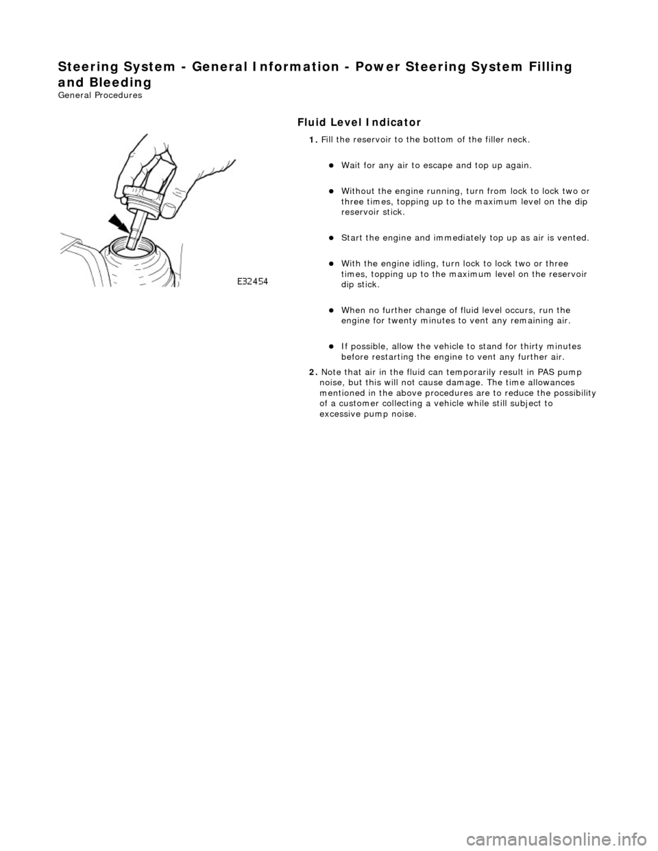
1.
F
ill the reservoir to the bo
ttom of the filler neck.
W
ait for any air to escape and top up again.
W
ithout the engine running, tu
rn from lock to lock two or
three times, topping up to the maximum level on the dip
reservoir stick.
St
art the engine and
immediately top up as air is vented.
W
ith the engine idling, turn
lock to lock two or three
times, topping up to the ma ximum level on the reservoir
dip stick.
W
hen no further change of
fluid level occurs, run the
engine for twenty minutes to vent any remaining air.
If po
ssible, allow the vehicle
to stand for thirty minutes
before restarting the engine to vent any further air.
2. Note that air in the fluid can temporarily result in PAS pump
noise, but this will not cause damage. The time allowances
mentioned in the above procedures are to reduce the possibility
of a customer collecting a vehicle while still subject to
excessive pump noise.
Page 476 of 2490

Steering System - Gen
eral Informatio
n - Power Steering System Vacuum
Filling and Bleeding
Gen e
ral Procedures
Fluid Ho
ses
1.
Parts L i
st
It
e
m
De
scr
iption
1R
e
turn hose
2High
pressure h
ose
2. If vacuum filling equipment is available, proceed as follows:
Disconnect both the
high pres
sure hose and return hose
from the PAS pump and the re turn hose from the steering
rack.
D rain as much fl
uid as possible from the system by
turning the steering from lock to lock two or three times.
Re conn
ect all hoses.
Fi
ll
the system using the vacuum equipment according to
the manufacturers instructions.
St art
the engine and top up
the fluid as necessary.
Turn the steering from lock to lock two or three ti mes wi
th
the engine running, topping up with fluid as necessary.
If possibl
e, run the engine for twenty minutes to expel any
remaining air.
Page 478 of 2490
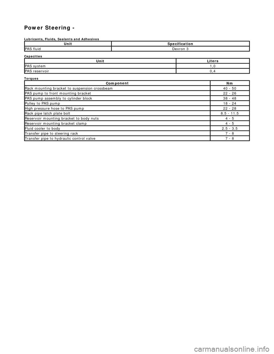
Power Steering -
Lubric
ants, Fluids, Sealants and Adhesives
Capacities
Torques
UnitSp
ecification
PAS flu
i
d
De
xr
on 3
UnitLi
t
ers
PAS syste
m1,0
PAS reservoi
r0,4
Com p
onent
Nm
Rac
k
mountin
g brac
ke
t to suspension crossbeam
40
- 50
PAS pump to front mounti
ng bracket
22
-
26
P
AS pu
mp assembly to cylinder block
38
-
48
Pul
l
ey to PAS pump
18
-
24
Hi
gh pressure hose to PAS pump22 -
28
Rack
pipe latch plate bolt8.5 -
11.5
R
e
servoir mounting bracket to body nuts
4 -
5
R
e
servoir mounting bracket clamp
4 -
5
Fluid cooler to body2.
5 -
3.5
Transfer pipe
to steering rack7 -
8
Transfer pipe
to hydraulic con
trol valve
7 -
8
Page 479 of 2490
Power Steering - Power Steering
Description an
d Operation
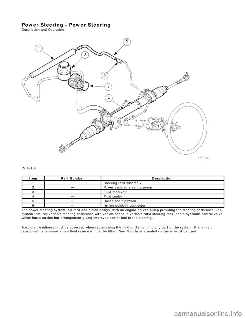
Parts List
The power steering system is a rack and pinion design, with an engine-dri ve n pump providing the steering assistance. The
system features variable steering assistance with vehicle spee d, a variable ratio steering rack, and a hydraulic control valve
which has a torsion bar arrangement giving improved center feel to the steering.
Absolute cleanliness must be observed wh en replenishing the fluid or dismantling any part of the system. If any major
component is renewed a new fluid rese rvoir must be fitted. New fluid from a sealed container must be used.
It
em
Par
t Number
De
scription
1—Steeri
ng rack assembly
2—Power as
sisted steering pump
3—F
luid reservoir
4—F
luid cooler
5—Hoses and pipework
6—In-
line quick-fit connector
Page 484 of 2490
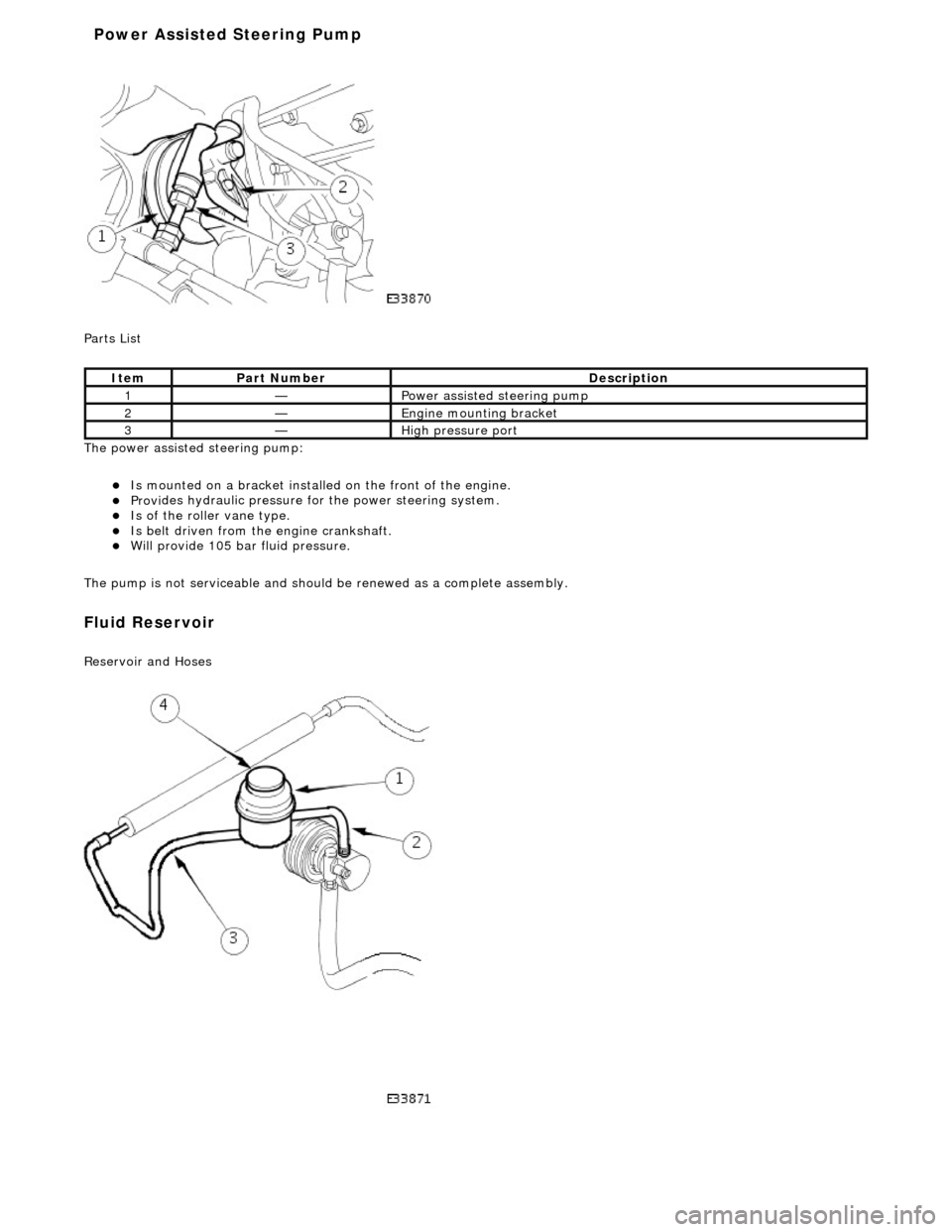
P a
rts List
The power assisted steering pump:
Is mo u
nted on a bracket installe
d on the front of the engine.
Provides hydraul
ic pressure fo
r the power steering system.
Is of the roll
er vane type.
Is belt driven from th
e en
gine crankshaft.
Will provide 1
05 bar f
luid pressure.
The pump is not serviceable and should be renewed as a complete assembly.
Fluid Reservoir
Re
servoir and Hoses
Ite
m
Par
t
Number
De
scr
iption
1—Power as
si
sted steering pump
2—Engine
m
ounting bracket
3—High
pressure port
Power Assisted Steering Pump
Page 490 of 2490
Power Steering - Power Steering
Diagn
osis and Testing
Refer to the Description and Operation sub-section for details of the power operated steering system and Servotronic control
system.
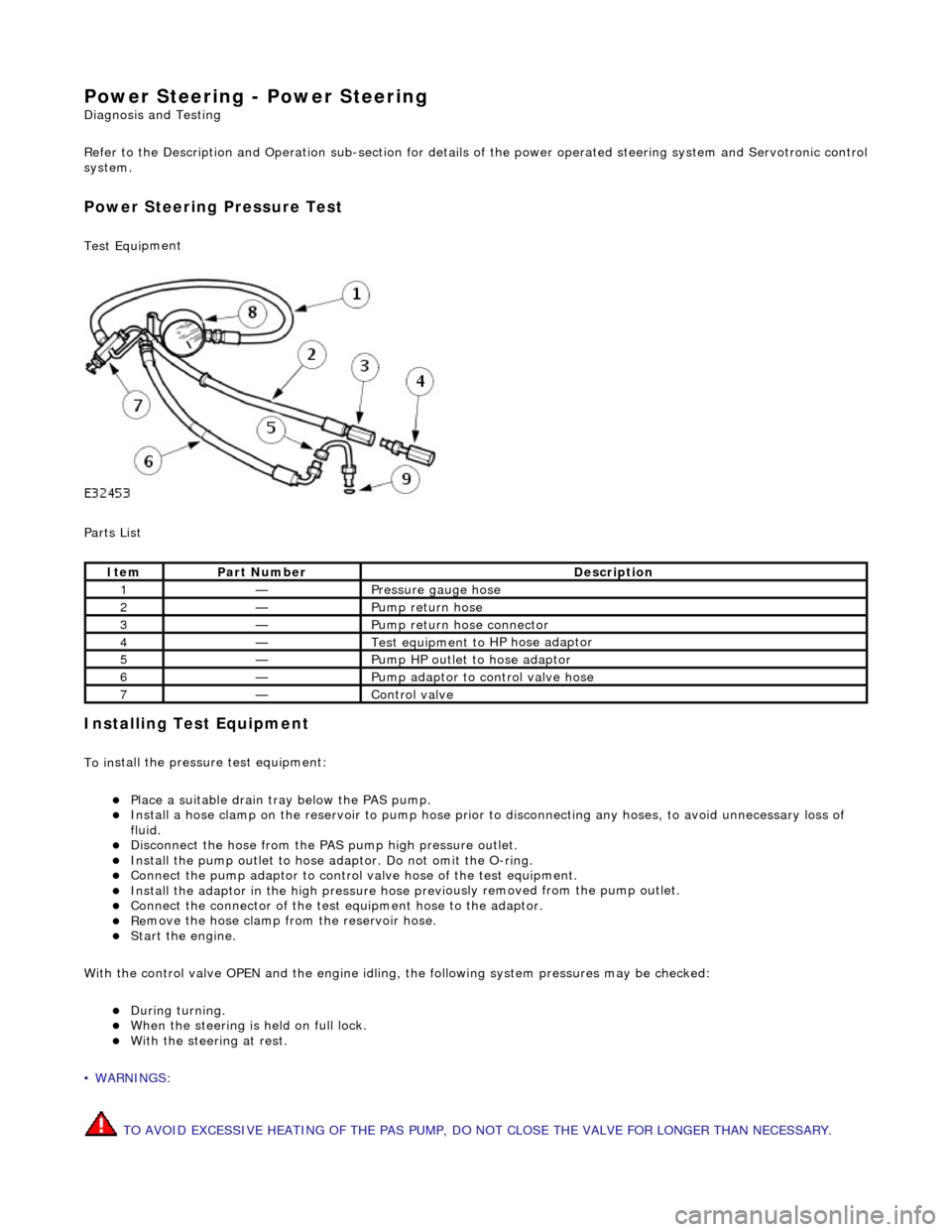
Power Steer ing Pressure Test
Test Equ
i
pment
Parts List
In
stalling Test Equipment
To
in
stall the pressure test equipment:
Pla
c
e a suitable drain tray below the PAS pump.
Install a hose clamp
on
the re
servoir to pump hose prior to disconnecting any hoses, to avoid unnecessary loss of
fluid.
Di sc
onnect the hose from the PAS pump high pres
sure outlet.
Ins
tall the pump outlet to hose ad
aptor. Do not omit the O-ring.
Conn
ect the pump adaptor to control valve hose of the test equipment.
Install th
e adaptor in the high pressure hose previ
ously re
moved from the pump outlet.
Conne
ct the connector of the test equipment hose to the adaptor.
R
e
move the hose clamp fro
m the reservoir hose.
Start th
e engine.
With the control valve OPEN and the engine idling , the following system pressures may be checked:
Du
ring turning.
W
h
en the steering is
held on full lock.
With
the steeri
ng at rest.
• WARNINGS:
TO AVOID EXCESSIVE HEATING OF THE PAS PUMP, DO NOT CLOSE THE VALVE FOR LONGER THAN NECESSARY.
Ite
m
Par
t
Number
De
scr
iption
1—Pressure
gauge hose
2—Pump return hose
3—Pump return hose connector
4—Test equi
pment to
HP hose adaptor
5—Pump HP outlet to hose adaptor
6—Pump adaptor
to control valve hose
7—Control valve
Page 903 of 2490
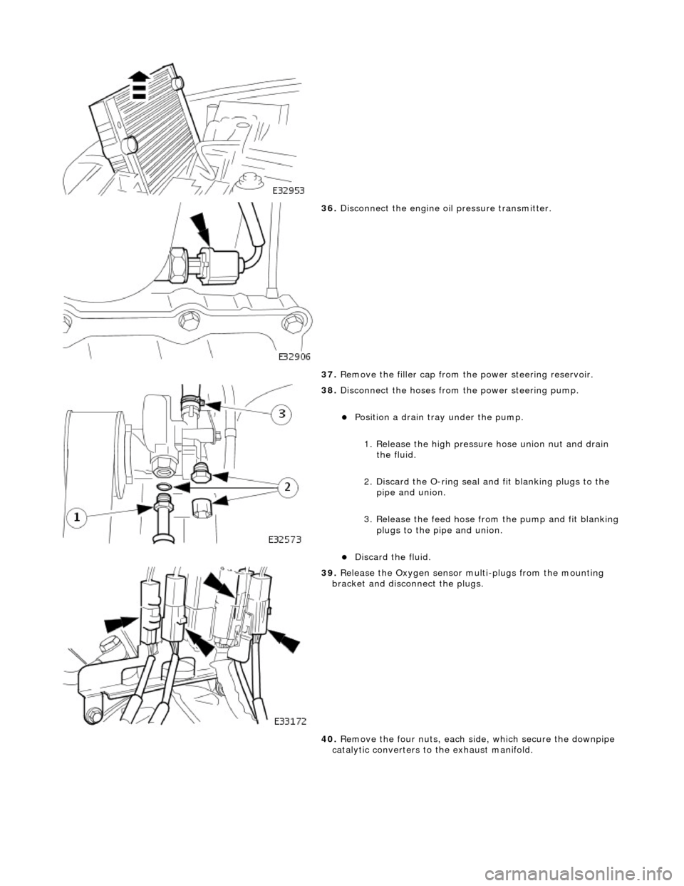
36. Disconnect the engine oi l pressure transmitter.
37. Remove the filler cap from the power steering reservoir.
38. Disconnect the hoses from the power steering pump.
Position a drain tray under the pump.
1. Release the high pressure hose union nut and drain the fluid.
2. Discard the O-ring seal an d fit blanking plugs to the
pipe and union.
3. Release the feed hose from the pump and fit blanking
plugs to the pipe and union.
Discard the fluid.
39. Release the Oxygen sensor multi-plugs from the mounting
bracket and disconnect the plugs.
40. Remove the four nuts, each side, which secure the downpipe
catalytic converters to the exhaust manifold.
Page 917 of 2490
WARNING: B
EFORE PROCEEDING, IT IS ESSENTIAL THAT
THE WARNING NOTES GIVEN IN SECTION 100-00 (UNDER
THE HEADING 'SAFETY PRECAUTION S') ARE READ AND UNDERSTOOD.
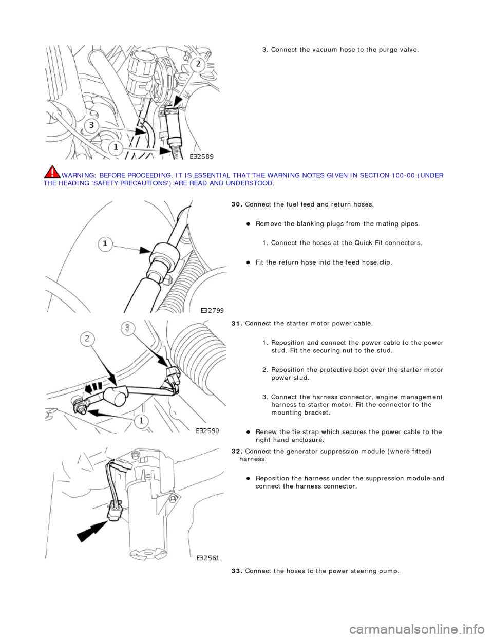
3.
Connect the vacuum hose to the purge valve.
30
.
Connect the fuel feed and return hoses.
R
emove the blanking plugs
from the mating pipes.
1. Connect the hoses at the Quick Fit connectors.
F
it the return hose into the feed hose clip.
31
.
Connect the starter motor power cable.
1. Reposition and connect the power cable to the power stud. Fit the securing nut to the stud.
2. Reposition the protective boot over the starter motor power stud.
3. Connect the harness connector, engine management harness to starter motor. Fit the connector to the
mounting bracket.
R
enew the tie strap which secures the power cable to the
right hand enclosure.
32
.
Connect the generator suppressi on module (where fitted)
harness.
Re
position the harn
ess under the suppression module and
connect the harness connector.
33. Connect the hoses to the power steering pump.
Page 1049 of 2490

Accessory Drive - Accessory Drive
Description an
d Operation
Parts List
Cran
kshaft Pulley
The combined crankshaft
pulley and torsio
nal vibration damper drives a single, seve n ribbed vee belt. The belt drives all of
the engine-mounted accessories; the generator, the power assi sted steering pump, the air-conditioning compressor and the
coolant water pump.
I
dler Pulley
An i
dler pulley, on the right-hand
accessory mounting, increases the wrap-angle around the generator pulley.
Coolant Pump Drive
The coolan
t pump pulley is the
uppermost of the accessory drive pulleys. Th e coolant pump is fitted between the two
cylinder banks on the front face of the engine.
Air Conditioning Compressor Drive
Thi
s is positioned at the lowest poin
t of the front-end accessory-d rive on the left hand side accessory mounting.
It
em
Par
t Number
De
scription
1—Coo
lant Pump Drive
2—Ai
r-Conditioning Compressor Drive
3—Power Steer
ing Pump Drive
4—Au
tomatic Belt Tensioner
5—Crankshaft Pul
ley
6—Idle
r Pulley
7—Generator Dri
ve