Power steering pump JAGUAR X308 1998 2.G Owner's Manual
[x] Cancel search | Manufacturer: JAGUAR, Model Year: 1998, Model line: X308, Model: JAGUAR X308 1998 2.GPages: 2490, PDF Size: 69.81 MB
Page 1050 of 2490
Power Assisted Steering Pump Drive
The power assisted steering pump pull
ey
is located on the left side, above the air-conditioning compressor.
Generator Dr
ive
The genera
tor is fitted on the
right hand accessory mounting.
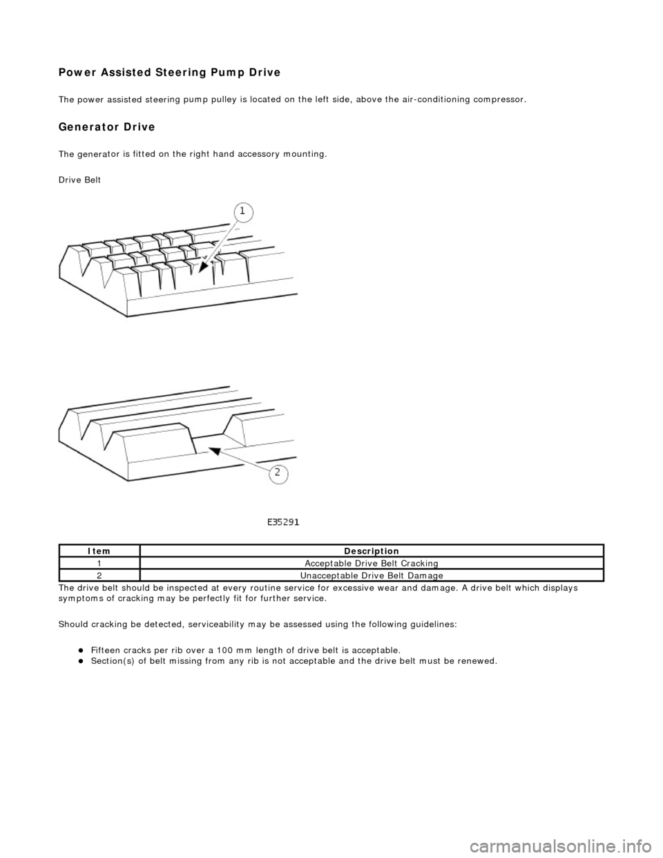
Drive Belt
The drive belt should be inspected at every routine service for excessive wear and damage. A drive belt which displays
symptoms of cracking may be pe rfectly fit for further service.
Should cracking be detected, serviceability ma y be assessed using the following guidelines:
Fi
fteen cracks per rib over a 100 mm le
ngth of drive belt is acceptable.
Sec
tion(s) of belt missing from an
y rib is not acceptable and the drive belt must be renewed.
Ite
m
De
scr
iption
1Ac
c
eptable Drive Belt Cracking
2Unacceptable Drive Belt Damage
Page 1804 of 2490
Air Conditioning - Air Conditioning (A/C) Compressor
Removal and Installation
Removal
1. Disconnect battery ground cable (IMPORTANT, see SRO
86.15.19 for further information).
2. Recover refrigerant from air co nditioning system; refer to
82.30.30.
3. Remove supercharger drive belt (where fitted); refer to
18.50.08.
4. Remove front end accessory dr ive belt; refer to 12.10.40 or
(SC) 12.10.40.
5. NOTE: A commercially availa ble brake pipe clamp is
recommended. Do not over tighten.
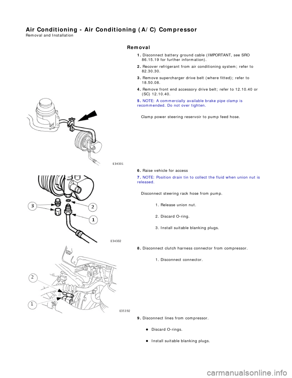
Clamp power steering reservoir to pump feed hose.
6. Raise vehicle for access
7. NOTE: Position drain tin to collect the fluid when union nut is
released.
Disconnect steering rack hose from pump. 1. Release union nut.
2. Discard O-ring.
3. Install suitable blanking plugs.
8. Disconnect clutch harness connector from compressor.
1. Disconnect connector.
9. Disconnect lines from compressor.
Discard O-rings.
Install suitable blanking plugs.
Page 1806 of 2490
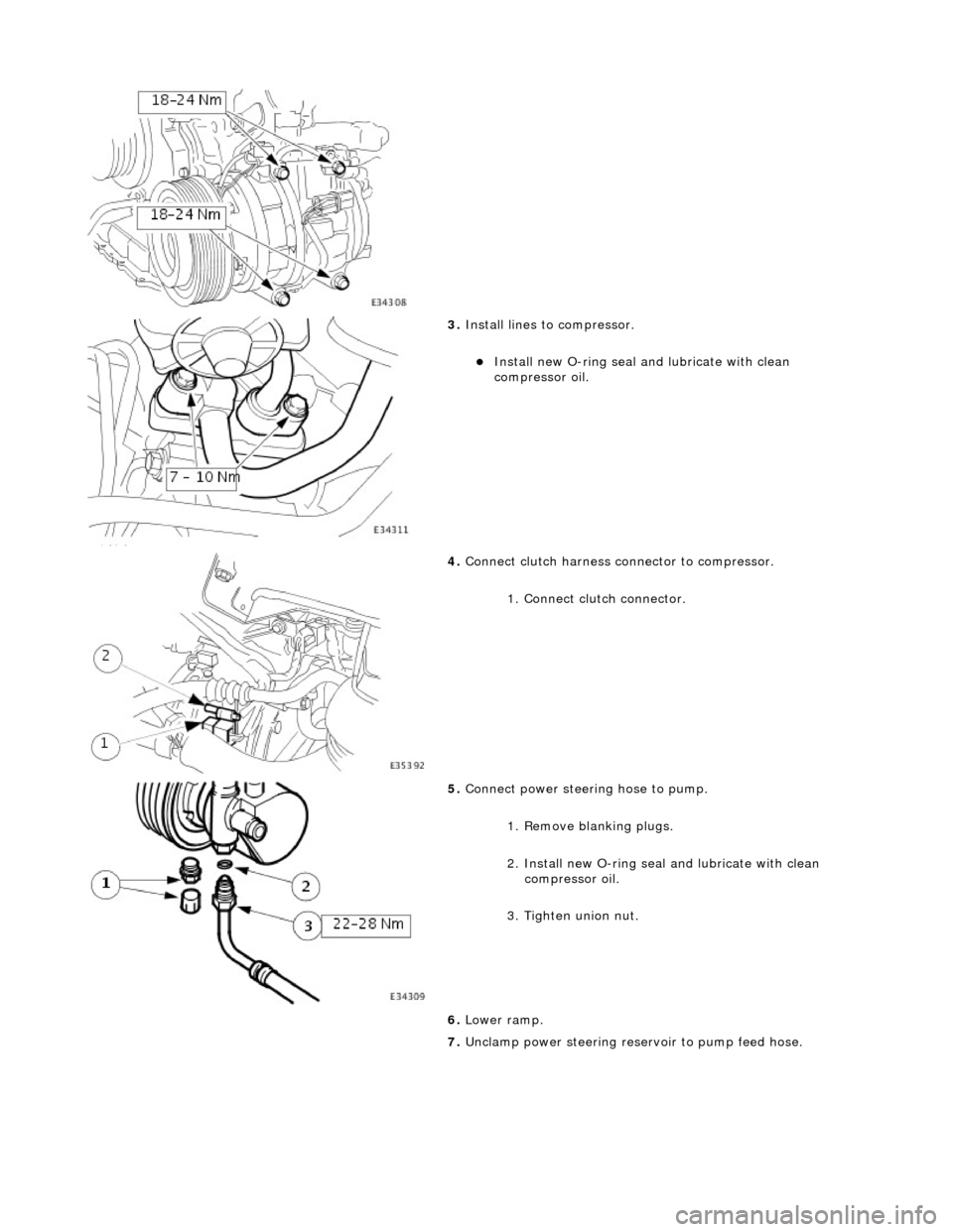
3. Install lines to compressor.
Install new O-ring seal and lubricate with clean
compressor oil.
4. Connect clutch harness connector to compressor.
1. Connect clutch connector.
5. Connect power steering hose to pump.
1. Remove blanking plugs.
2. Install new O-ring seal and lubricate with clean
compressor oil.
3. Tighten union nut.
6. Lower ramp.
7. Unclamp power steering rese rvoir to pump feed hose.
Page 1975 of 2490
Location of J1962 socket
The J1962 socket is located at the driver side inboard footwell.
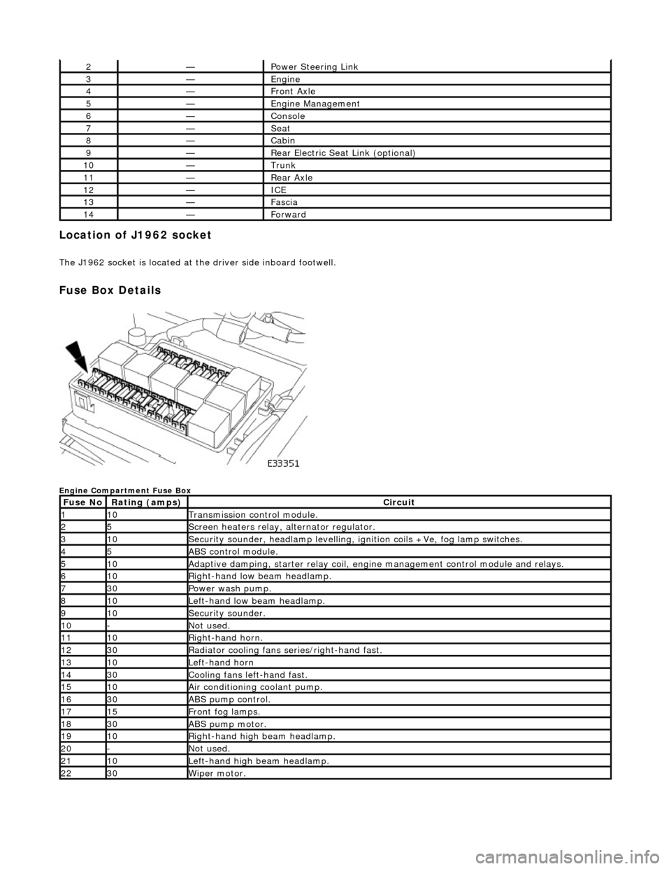
Fuse Box Details
Engine Compartment Fuse Box
2—Power Steering Link
3—Engine
4—Front Axle
5—Engine Management
6—Console
7—Seat
8—Cabin
9—Rear Electric Seat Link (optional)
10—Trunk
11—Rear Axle
12—ICE
13—Fascia
14—Forward
Fuse NoRating (amps)Circuit
110Transmission control module.
25Screen heaters relay, alternator regulator.
310Security sounder, headlamp levelling, ignition coils +Ve, fog lamp switches.
45ABS control module.
510Adaptive damping, starter relay coil, engine management control module and relays.
610Right-hand low beam headlamp.
730Power wash pump.
810Left-hand low beam headlamp.
910Security sounder.
10-Not used.
1110Right-hand horn.
1230Radiator cooling fans series/right-hand fast.
1310Left-hand horn
1430Cooling fans left-hand fast.
1510Air conditioning coolant pump.
1630ABS pump control.
1715Front fog lamps.
1830ABS pump motor.
1910Right-hand high beam headlamp.
20-Not used.
2110Left-hand high beam headlamp.
2230Wiper motor.
Page 2008 of 2490
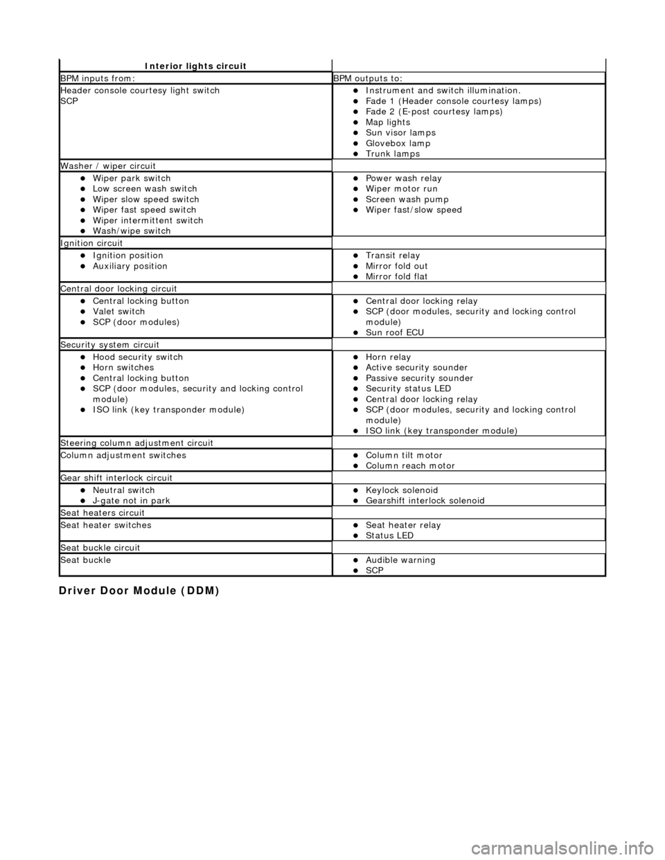
Driver Door Module (DDM)
Interior lights circuit
BPM inputs from: BPM outputs to:
Header console courtesy light switch
SCPInstrument and switch illumination. Fade 1 (Header console courtesy lamps) Fade 2 (E-post courtesy lamps) Map lights Sun visor lamps Glovebox lamp Trunk lamps
Washer / wiper circuit
Wiper park switch Low screen wash switch Wiper slow speed switch Wiper fast speed switch Wiper intermittent switch Wash/wipe switch
Power wash relay Wiper motor run Screen wash pump Wiper fast/slow speed
Ignition circuit
Ignition position Auxiliary position Transit relay Mirror fold out Mirror fold flat
Central door locking circuit
Central locking button Valet switch SCP (door modules)
Central door locking relay SCP (door modules, security and locking control
module)
Sun roof ECU
Security system circuit
Hood security switch Horn switches Central locking button SCP (door modules, security and locking control
module)
ISO link (key transponder module)
Horn relay Active security sounder Passive security sounder Security status LED Central door locking relay SCP (door modules, security and locking control
module)
ISO link (key transponder module)
Steering column adjustment circuit
Column adjustment switchesColumn tilt motor Column reach motor
Gear shift interlock circuit
Neutral switch J-gate not in park Keylock solenoid Gearshift interlock solenoid
Seat heaters circuit
Seat heater switchesSeat heater relay Status LED
Seat buckle circuit
Seat buckleAudible warning SCP