Power steering pump JAGUAR X308 1998 2.G Workshop Manual
[x] Cancel search | Manufacturer: JAGUAR, Model Year: 1998, Model line: X308, Model: JAGUAR X308 1998 2.GPages: 2490, PDF Size: 69.81 MB
Page 46 of 2490
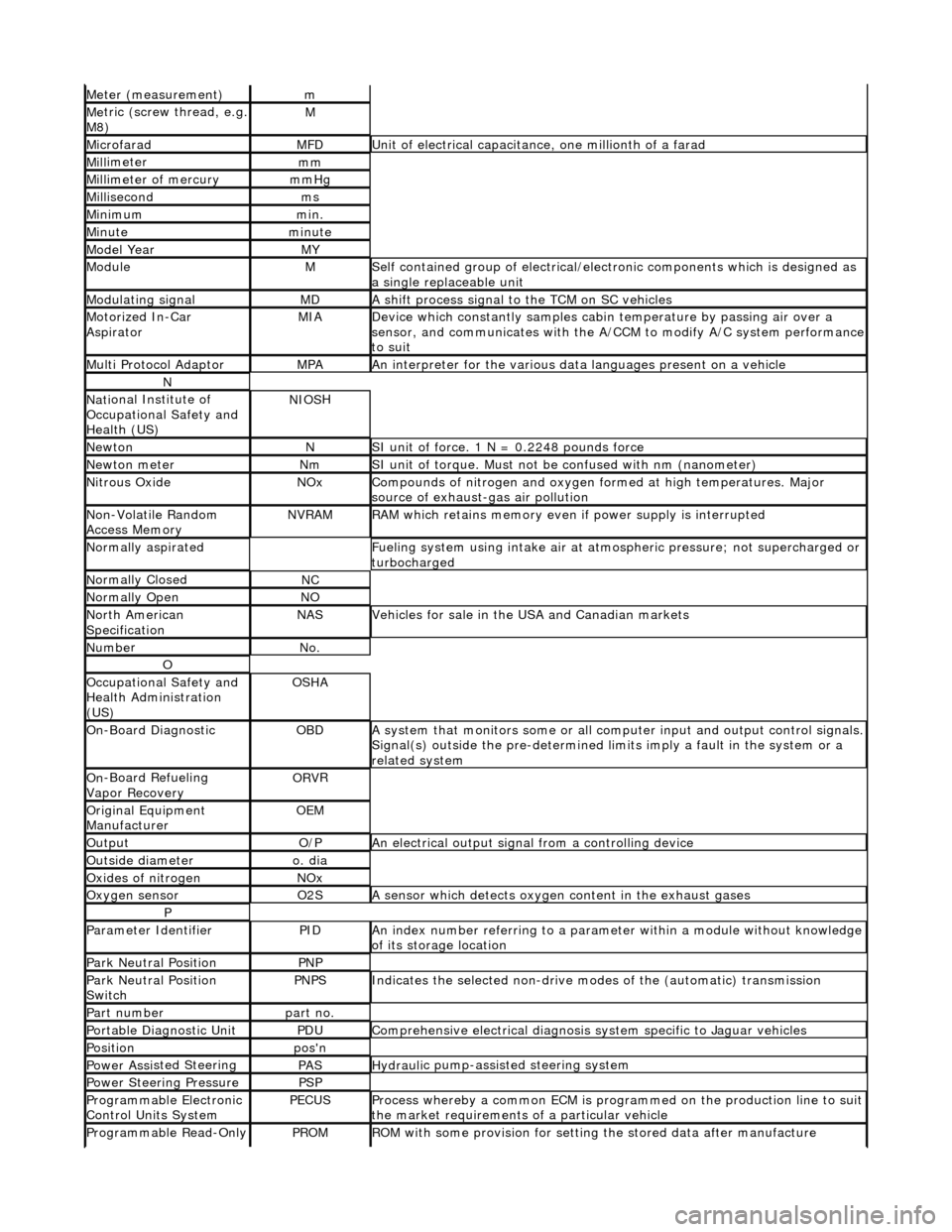
Meter (measurement)m
Me
tric (screw thread, e.g.
M8)
M
MicrofaradMFDUni t
of electrical capacitance, one millionth of a farad
Mi
ll
imeter
mm
Mi
ll
imeter of mercury
mm
Hg
Mill
isecond
ms
Min
i
mum
mi
n.
Min u
te
minut
e
Model YearMY
ModuleMSelf
contained group of electrical/electronic components which is designed as
a single replaceable unit
Modulating signalMDA sh
ift process signal to the TCM on SC vehicles
Motorized In
-Car
AspiratorMIAD e
vice which constantly samples cabi
n temperature by passing air over a
sensor, and communicates with the A/ CCM to modify A/C system performance
to suit
Mult i Prot
ocol Adaptor
MPAAn i
n
terpreter for the various data
languages present on a vehicle
N
Nati
onal Institute of
Occupational Safety and
Health (US)
NIO S
H
Ne
wto
n
NSI unit of force. 1
N = 0.224
8 pounds force
Ne
wto
n meter
NmSI unit of torque. Must not be
co
nfused with nm (nanometer)
Ni
tr
ous Oxide
NO
xCompounds of nit rogen and oxygen fo rmed at high temperatures. Major
sourc
e of exhaust-gas air pollution
No
n
-Volatile Random
Access Memory
NVR A
M
R
A
M which retains memory even
if power supply is interrupted
Normal
ly aspirated
F
u
eling system using intake air at atmo
spheric pressure; not supercharged or
turbocharged
N ormal
ly Closed
NC
N
o
rmally Open
NO
No
r
th American
Specification
NASVehicles f or sal
e in the USA and Canadian markets
Nu
mbe
r
No
.
O
Oc
cupational Safety and
Health Administration
(US)
OS H
A
O
n
-Board Diagnostic
OB
DA system that moni
tors some or all co
mputer input and output control signals.
Signal(s) outside the pre-de termined limits imply a fault in the system or a
related system
O n
-Board Refueling
Vapor Recovery
OR V
R
O
riginal
Equipment
Manufacturer
OE M
Outp
ut
O/
PAn electrical o u
tput signal from a controlling device
Ou
ts
ide diameter
o.
d
ia
O
xides of
nitrogen
NO
x
Oxygen senso
r
O2
SA s
ensor which detects oxygen content in the exhaust gases
P
Parameter Identifi
erPIDAn in
dex number referring to a parame
ter within a module without knowledge
of its storage location
Park N e
utral Position
PN
P
Park N e
utral Position
Switch
PN PSIndic
ates the selected non-drive modes of the (automatic) transmission
Part numberpart no.
Portable Diag
nostic Un
it
PD
UCompre hen
sive electrical diagnosis system specific to Jaguar vehicles
Posi
ti
on
po
s'n
Power As si
sted Steering
PASHydraul
i
c pump-assisted steering system
Power Steer
i
ng Pressure
PSP
Programmable Elect
r
onic
Control Units System
PECU SProcess whereb y
a common ECM is progra
mmed on the production line to suit
the market requirements of a particular vehicle
Programmable Read-O
nly
PROMRO
M with some provision for setting
the stored data after manufacture
Page 453 of 2490
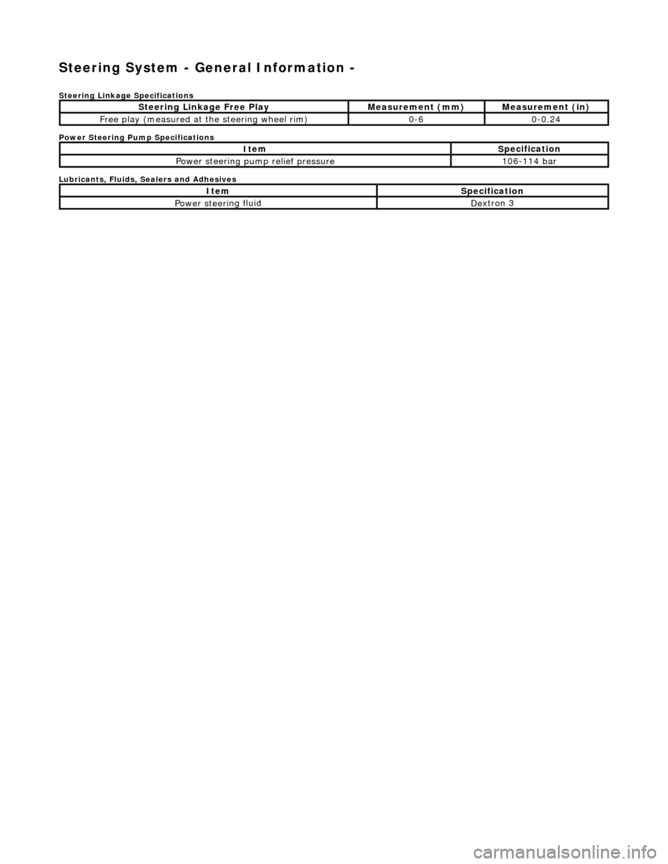
Stee
ring System - General Information -
S
teering Linkage Specifications
Power Steering Pump Specifications
Lubricants, Fluids, Sealers and Adhesives
S
teering Linkage Free Play
Meas
urement (mm)
Meas
urement (in)
F
ree play (measured at
the steering wheel rim)
0-
6
0
-0.24
It
em
S
pecification
Power steeri
ng pump relief pressure
10
6-114 bar
It
em
S
pecification
Power steeri
ng fluid
De
xtron 3
Page 455 of 2490
Steering System - General Inform
ation - Steering System
D
iagnosis and Testing
I
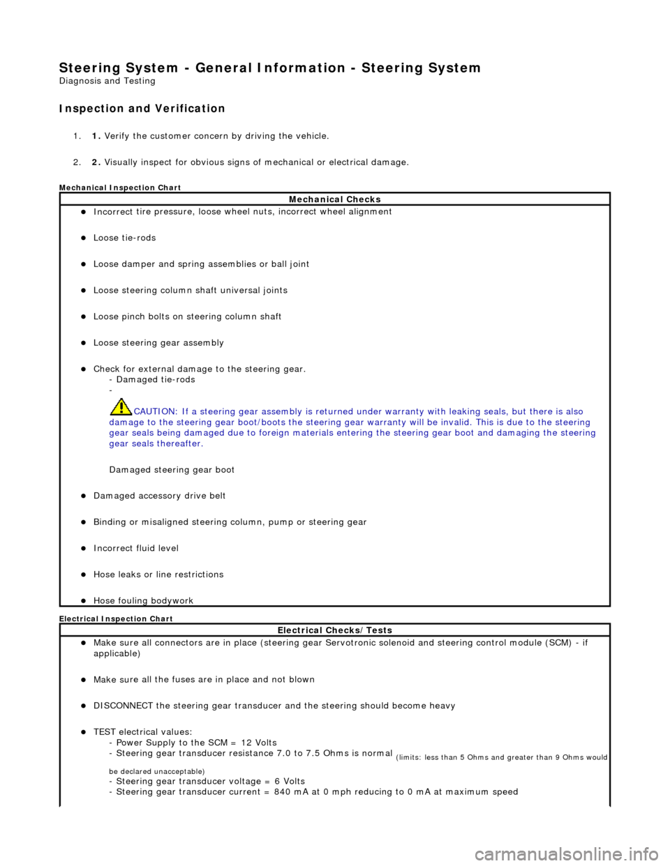
nspection and Verification
1.
1. Verify t
he customer concern by driving the vehicle.
2. 2. Visually inspect for obvious signs of mechanical or electrical damage.
Mec
hanical Inspection Chart
Electrical Inspection Chart
Mechanical Checks
Incorrect
tire pressure, loose whee
l nuts, incorrect wheel alignment
Loose ti
e-rods
Loose dam
per and spring assemblies or ball joint
Loose s
teering column shaft universal joints
Loose pinc
h bolts on steering column shaft
Loose steeri
ng gear assembly
Check f
or external damage to the steering gear.
- Damaged tie-rods
-
CAUTION: If a steering gear assemb ly is returned under warranty with leaking seals, but there is also
damage to the steering gear boot/boots the steering gear warranty will be invalid. This is due to the steering
gear seals being damaged due to fore ign materials entering the steering gear boot and damaging the steering
gear seals thereafter.
Damaged steering gear boot
Damaged accessory driv
e belt
Bin
ding or misaligned steering co
lumn, pump or steering gear
Incorrect fluid
level
Hose leaks o
r line restrictions
Hose fou
ling bodywork
El
ectrical Checks/Tests
Make sure all
connectors are in plac
e (steering gear Servotronic solenoid and steering control module (SCM) - if
applicable)
Make su
re all the fuses are in place and not blown
D
ISCONNECT the steering gear transducer
and the steering should become heavy
TEST e
lectrical values:
- Power Supply to the SCM = 12 Volts
- Steering gear transducer resist ance 7.0 to 7.5 Ohms is normal
(
limits: less than 5 Ohms and greater than 9 Ohms would
be declared unacceptable)
- Steeri
ng gear transducer voltage = 6 Volts
- Steering gear transducer cu rrent = 840 mA at 0 mph reducing to 0 mA at maximum speed
Page 457 of 2490
•
NOTE: The following steps must be carried out with assistance.
1. 1. With the wheels in the straight ahead po sition, gently turn the steering wheel to the left and the right to check for
free play.
2. 2. Free play should be between 0 and 6 mm (0 and 0.24 in) at the steering wheel rim. If the free play exceeds this
limit, either the ball joints are worn, the lower steering column joints are worn or the backlash of the steering gear
is excessive.
CAUTION: DO NOT attempt to adjust the stee ring gear yoke. Failure to follow this instruction will result in the steering
gear warranty to become invalid.
3. 3. The backlash of the steering gear cannot be adjusted, in stall a new steering gear. For additional information,
REFER to Section 211
-0
2 Power Steering
.
4. 4. Grasp the steering wheel
firm
ly and move it up and down and to the left and right without turning the wheel to
check for column bearing wear, steering wheel or steering column. For additional information,
REFER to Section 211
-0
4 Steering Column
.
Power Steering Fluid Condition Check
1.
1. R
un the engine for 2 minutes.
2. 2. Check the power steering fluid system level.
3. 3. Observe the color and the odor. The color under normal circumstances should be dark reddish, not brown or
black.
4. 4. Allow the fluid to drip onto a faci al tissue and examine the stain.
5. 5. If evidence of solid material is foun d, the power steering fluid system should be drained for further inspection.
6. 6. If fluid contamination or steering co mponent failure is confirmed by the se diment in the power steering fluid
system, REFER to Steering Fault Diagnosis by Symptom Charts in this section.
Power Steer
ing Pressure Test
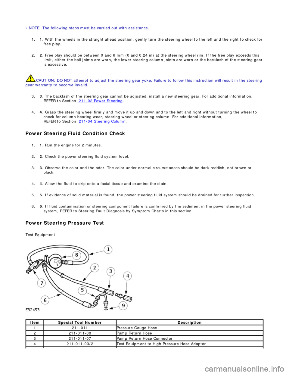
Test Equ
ipment
It
em
S
pecial Tool Number
De
scription
12
11-011
Pres
sure Gauge Hose
221
1-011-08
Pump Return Hose
321
1-011-07
Pump Return Hose Connector
42
11-011-03/2
Test Equ
ipment to High
Pressure Hose Adaptor
Page 458 of 2490
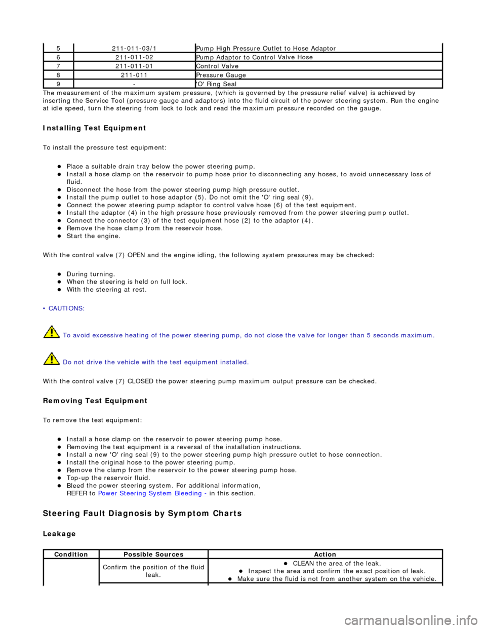
The
measurement of the maximum system pressure, (which is
governed by the pressure relief valve) is achieved by
inserting the Service Tool (pressure gauge and adaptors) into th e fluid circuit of the power steering system. Run the engine
at idle speed, turn the st eering from lock to lock and read the ma ximum pressure recorded on the gauge.
Installin
g Test Equipment
To
in
stall the pressure test equipment:
Pla
c
e a suitable drain tray be
low the power steering pump.
Install a hose clamp on
the re
servoir to pump hose prior to disconnecting any hoses, to avoid unnecessary loss of
fluid.
Disc
onnect the hose from the power st
eering pump high pressure outlet.
Install the pu
mp outlet to hose adaptor (5
). Do not omit the 'O' ring seal (9).
Connect the power steering
pump
adaptor to control valve hose (6) of the test equipment.
Install th e adaptor (4) in th
e high
pressure hose previously removed from the power steering pump outlet.
Conn
ect the connector (3) of the test equipment hose (2) to the adaptor (4).
R
e
move the hose clamp fro
m the reservoir hose.
Start th
e engine.
With the control valve (7) OPEN and the engine idli ng, the following system pressures may be checked:
Du
ring turning.
W
h
en the steering is
held on full lock.
With
the steeri
ng at rest.
• CAUTIONS:
To avoid excessive heating of the po wer steering pump, do not close the valve for longer than 5 seconds maximum.
Do not drive the vehicle with the test equipment installed.
With the control valve (7) CLOSED the power steering pump maximum ou tput pressure can be checked.
Removing Test Equipment
To
remove the test equipment:
Install a hose clamp
on
the reservoir to power steering pump hose.
Re
movi
ng the test equipmen
t is a reversal of the in stallation instructions.
Install a new '
O
' ring seal (9) to the power steering pump high pressu
re outlet to hose connection.
Instal
l the original hose to
the power steering pump.
Re
move the clamp from the reservoir to
the power steering pump hose.
Top-up the reservoir flui
d.
Ble
e
d the power steerin
g system. For additional information,
REFER to Power Steering System Bleeding
- in thi
s section.
Stee
ring Fault Diagnosis by Sympt
om Charts
Leakage
52
11-0
11-03/1
Pump High Pressure Ou
tlet
to Hose Adaptor
621
1
-011-02
Pump Adaptor
to Contro
l Valve Hose
721
1
-011-01
Control Valve
82
11-
011
Pressure Gauge
9-'O
'
Ring Seal
Cond
iti
on
Possib
l
e Sources
Acti
o
n
Co
nfirm
the position of the fluid
leak.
CLEAN th
e area of the leak.
In
s
pect the area and confirm the exact position of leak.
Make sure the fluid
is not from anoth
er system on
the vehicle.
Page 459 of 2490
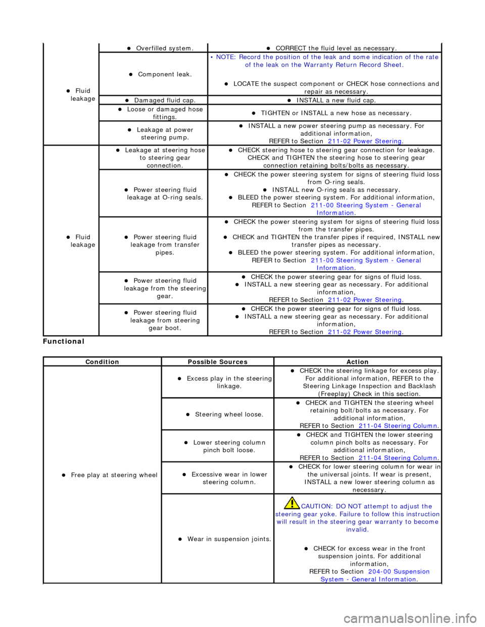
Function
al
Fl
uid
leakage
O
verfilled system.
CORRECT the
fluid leve
l as necessary.
Compon
ent leak.
•
NOTE: Record the position of the le
ak and some indication of the rate
of the leak on the Warra nty Return Record Sheet.
LOCATE
the suspect component or CHECK hose connections and
repair as necessary.
Damaged fluid cap. INST
ALL a new fluid cap.
Loose or damaged h
ose
fittings.
TI
GHTEN or INSTALL a new hose as necessary.
Leakage at
power
steering pump.
INST
ALL a new power steering
pump as necessary. For
additional information,
REFER to Section 211
-0
2 Power Steering
.
Fl
uid
leakage
Leakage
at steering hose
to steering gear connection.
CHECK
steering hose to
steering gear conn ection for leakage.
CHECK and TIGHTEN the steeri ng hose to steering gear
connection retaining bolt s/bolts as necessary.
Power steeri
ng fluid
leakage at O-ring seals.
CHECK
the power steering system fo
r signs of steering fluid loss
from O-ring seals.
INST
ALL new O-ring seals as necessary.
BLEE
D the power steering system.
For additional information,
REF
ER to Section 211
-0
0 Steering System
- Ge
neral
Informati
on
.
Power steeri
ng fluid
leakage from transfer pipes.
CHECK
the power steering system fo
r signs of steering fluid loss
from the transfer pipes.
CHECK
and TIGHTEN the transfer pipes if required, INSTALL new
transfer pipes as necessary.
BLEE
D the power steering system.
For additional information,
REF
ER to Section 211
-0
0 Steering System
- Ge
neral
Informati
on
.
Power steeri
ng fluid
leakage from the steering
gear.
CHECK
the power steering gear for signs of fluid loss.
INST
ALL a new steering gear as
necessary. For additional
information,
REFER to Section 211
-0
2 Power Steering
.
Power steeri
ng fluid
leakage from steering gear boot.
CHECK
the power steering gear for signs of fluid loss.
INST
ALL a new steering gear as
necessary. For additional
information,
REFER to Section 211
-0
2 Power Steering
.
Cond
ition
Possib
le Sources
Acti
on
F
ree play at steering wheel
Exce
ss play in the steering
linkage.
CHECK
the steering linkage for excess play.
For additional information, REFER to the
Steering Linkage Inspection and Backlash (Freeplay) Check in this section.
S
teering wheel loose.
CHECK
and TIGHTEN the steering wheel
retaining bolt/bolts as necessary. For additional information,
REFER to Section 211
-0
4 Steering Column
.
Lower steeri
ng column
pinch bolt loose.
CHECK
and TIGHTEN the lower steering
column pinch bolts as necessary. For additional information,
REFER to Section 211
-0
4 Steering Column
.
Exce
ssive wear in lower
steering column.
CHECK
for lower steering column for wear in
the universal joints. If wear is present,
INSTALL a new lower steering column as necessary.
W
ear in suspension joints.
CAU
TION: DO NOT attempt to adjust the
steering gear yoke. Failure to follow this instruction
will result in the steering gear warranty to become
invalid.
CHECK
for excess wear in the front
suspension joints. For additional information,
REFER to Section 204
-00
Suspension
Sy
stem
- General
Information
.
Page 462 of 2490
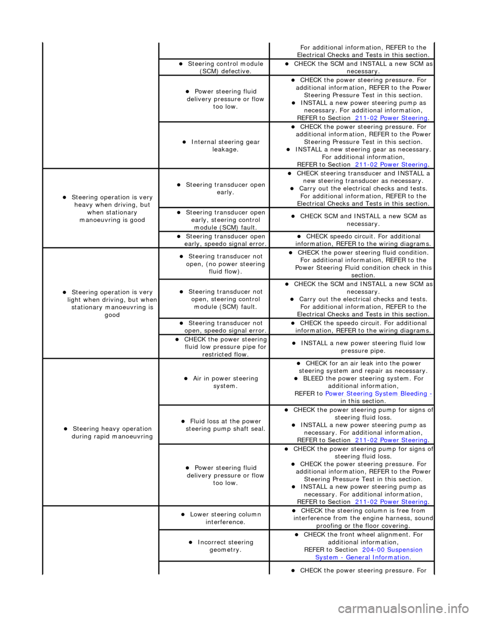
Fo
r additional information, REFER to the
Electrical Checks and Tests in this section.
Steering control
module
(SCM) defective.
CHECK
the SCM and INSTALL a new SCM as
necessary.
Power steeri ng f
luid
delivery pressure or flow too low.
CHECK
the power stee
ring pressure. For
additional information, REFER to the Power Steering Pressure Test in this section.
INSTALL a ne
w power steering pump as
necessary. For additi onal information,
REFER to Section 211
-0 2
Power Steering
.
Internal steering gear
leakage.
CHECK
the power stee
ring pressure. For
additional information, REFER to the Power Steering Pressure Test in this section.
INSTALL a ne
w steering
gear as necessary.
For additional information,
REFER to Section 211
-0 2
Power Steering
.
Steeri
ng operati
on is very
heavy when driving, but when stationary
manoeuvring is good
Steering transducer open earl
y.
CHECK
steering transducer and INSTALL a
new steering transducer as necessary.
Carry out th
e electrical checks and tests.
For additional information, REFER to the
Electrical Checks and Tests in this section.
Steering transducer open
early,
steering control
module (SCM) fault.
CHECK
SCM and INSTALL a new SCM as
necessary.
Steering transducer open
earl
y, speedo signal error.
CHECK
speedo
circui
t. For additional
information, REFER to the wiring diagrams.
Steeri ng operati
on is very
light when driving, but when
stationary manoeuvring is good
Steering transducer not
o
pen, (no power steering
fluid flow).
CHECK
the power steering fluid condition.
For additional information, REFER to the
Power Steering Fluid condition check in this section.
Steering transducer not o
pen, steering control
module (SCM) fault.
CHECK
the SCM and INSTALL a new SCM as
necessary.
Carry out th
e electrical checks and tests.
For additional information, REFER to the
Electrical Checks and Tests in this section.
Steering transducer not
o
pen, speedo signal error.
CHECK
the speedo circ
uit. For additional
information, REFER to the wiring diagrams.
CHECK
the power steering
fluid low pressure pipe for restricted flow.
INSTALL a ne
w power steering fluid low
pressure pipe.
S t
eering heavy operation
during rapid manoeuvring
Ai r i
n power steering
system.
CHECK for an air l
eak into the power
steering system and re pair as necessary.
BLEED the
power steering system. For
additional information,
REFER to Power Steering System Bleeding
- in t hi
s section.
Fluid loss at the power
steering pump shaft seal.
CHECK the power steer
ing pump for signs o
f steering fl
ui
d loss.
INST
ALL a ne
w power steering pump as
necessary. For additi onal information,
REFER to Section 211
-0 2
Power Steering
.
Power steeri
ng f
luid
delivery pressure or flow too low.
CHECK the power steer
ing pump for signs o
f steering fl
ui
d loss.
CHECK
the power stee
ring pressure. For
additional information, REFER to the Power Steering Pressure Test in this section.
INSTALL a ne
w power steering pump as
necessary. For additi onal information,
REFER to Section 211
-02
Power Steering
.
Lower steeri
ng col
umn
interference.
CHECK
the steering co
lumn is free from
interference from the en gine harness, sound
proofing or the floor covering.
Incorrect steering geometry. CHE
CK the front wheel alignment. For
additional information,
REFER to Section 204
-00 Sus
pension
Sy
ste
m
- General
Information
.
CHECK
the power stee
ring pressure. For
Page 463 of 2490
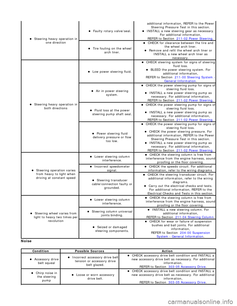
No
ise
S
teering heavy operation in
one direction
F
aulty rotary valve/seal.
addi
tional information, REFER to the Power
Steering Pressure Test in this section.
INST
ALL a new steering
gear as necessary.
For additional information,
REFER to Section 211
-0
2 Power Steering
.
Ti
re fouling on the wheel
arch liner.
CHECK for
clearance be
tween the tire and
the wheel arch liner.
R
emove and refit the wheel arch liner or
INSTALL a new wheel arch liner as necessary.
S
teering heavy operation in
both directions
Low power steer
ing fluid.
CHE
CK steering system
for signs of steering
fluid loss.
BLEE
D the power steering system. For
additional information,
REFER to Section 211
-0
0 Steering System
- General Informati
on
.
Ai
r in power steering
system.
CHECK
the power steering pump for signs o
f steering fl
uid loss.
INST
ALL a new power steering pump as
necessary. For additi onal information,
REFER to Section 211
-0
2 Power Steering
.
Fluid loss at the power
steering pump shaft seal.
CHECK
the power steering pump for signs o
f steering fl
uid loss.
INST
ALL a new power steering pump as
necessary. For additi onal information,
REFER to Section 211
-0
2 Power Steering
.
Power steeri
ng fluid
delivery pressure or flow too low.
CHECK
the power steering pump for signs o
f steering fl
uid loss.
CHECK
the power stee
ring pressure. For
additional information, REFER to the Power Steering Pressure Test in this section.
INST
ALL a new power steering pump as
necessary. For additi onal information,
REFER to Section 211
-0
2 Power Steering
.
Steeri
ng operation varies
from heavy to light when
driving at constant speed
Lower steeri
ng column
interference.
CHECK
the steering co
lumn is free from
interference from the en gine harness, sound
proofing or the floor covering.
Incorre
ct sp
eedometer
signal.
CHECK
the speedo circ
uit. For additional
information, refer to the wiring diagrams.
Steeri
ng transducer
cable/connection faulty or grounded.
CHECK
the steering transducer circuit. For
additional information, refer to the wiring diagrams.
Carry ou
t the electrical checks and tests.
For additional information, REFER to the
Electrical Checks and Tests in this section.
Steeri
ng wheel varies from
light to heavy two times per revolution
Lower steeri
ng column
interference.
CHECK
the steering co
lumn is free from
interference from the en gine harness, sound
proofing or the floor covering.
Steeri
ng column universal
joints binding.
IN
STALL a new steering column. For
additional information,
REFER to Section 211
-0
4 Steering Column
.
Seized or damaged
ste
ering components.
CHECK
for wear or failure of suspension
bushes and ball join ts. For additional
information,
REFER to Section 204
-00
Suspension
Sy
stem
- General
Information
.
Cond
ition
Possib
le Sources
Acti
on
Acce
ssory drive
belt squeal
Incorre
ct accessory drive belt
tension or accessory drive belt glazed.
CHECK
accessory drive belt condition and INSTALL a
new accessory drive belt as necessary. For additional
information,
REFER to Section 303
-0
5 Accessory Drive
.
Chir
p noise in
the steering pump
Loose or worn accessory dr
ive belt.
CHECK
accessory drive belt condition and INSTALL a
new accessory drive belt as necessary. For additional
information,
REFER to Section 303
-0
5 Accessory Drive
.
Page 464 of 2490
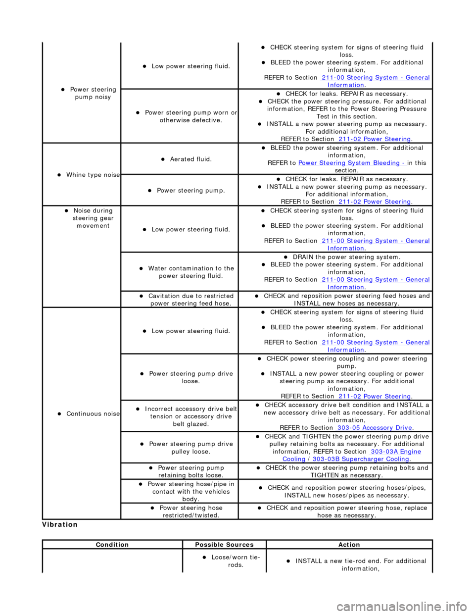
Vibrati
on
Power steeri
ng
pump noisy
Low power steer i
ng fluid.
CHECK
steering system for s
igns of steering fluid
loss.
BLEE D the
power steering system. For additional
information,
REFER to Section 211
-0 0
Steering System
-
Ge n
eral
Informati
o
n
.
Power steeri
ng pump wor
n or
otherwise defective.
CHECK for leaks. R
EPAIR as necessary.
CHECK
the power steering pressure. For additional
information, REFER to th e Power Steering Pressure
Test in this section.
INST ALL a ne
w power steering pump as necessary.
For additional information,
REFER to Section 211
-0 2
Power Steering
.
Wh
in
e type noise
Aerated flui
d.
BLEE
D the
power steering system. For additional
information,
REFER to Power Steering System Bleeding
- in t h
is
section.
Power steering pump.
CHECK for leaks. R
EPAIR as necessary.
INSTALL a ne
w power steering pump as necessary.
For additional information,
REFER to Section 211
-0 2
Power Steering
.
No
i
se during
steering gear movement
Low power steer i
ng fluid.
CHECK
steering system for s
igns of steering fluid
loss.
BLEE D the
power steering system. For additional
information,
REFER to Section 211
-0 0
Steering System
-
Ge n
eral
Informati
o
n
.
Water co
n
tamination to the
power steering fluid.
DR AIN
the power steering system.
BLEE
D the
power steering system. For additional
information,
REFER to Section 211
-00
Steering System
-
Gen
eral
Informati
o
n
.
Cavi
tation due to restricted
po
wer steering feed hose.
CHECK
and reposition power
steering feed hoses and
INSTALL new hoses as necessary.
Continu o
us noise
Low power steer i
ng fluid.
CHECK
steering system for s
igns of steering fluid
loss.
BLEE D the
power steering system. For additional
information,
REFER to Section 211
-0 0
Steering System
-
Ge n
eral
Informati
o
n
.
Power steeri
ng pump dri
ve
loose.
CHECK
power steering coupli
ng and power steering
pump.
IN ST
ALL a new power steering coupling or power
steering pump as nece ssary. For additional
information,
REFER to Section 211
-0 2
Power Steering
.
Incorre
ct
accessory drive belt
tension or accessory drive belt glazed.
CHECK acc
essory drive belt condition and INSTALL a
new accessory drive belt as necessary. For additional
information,
REFER to Section 303
-0 5 Ac
cessory Drive
.
Power steeri
ng pump dri
ve
pulley loose.
CHECK
and TIGHTEN the power steering pump drive
pulley retaining bolts as necessary. For additional
information, REFER to Section 303
-03A En
gine
Coo
ling / 30 3-03
B Supercharger Cooling
.
Power steeri
ng pump
r
etaining bolts loose.
CHECK
the power steering pump retaining bolts and
TIGHTEN as necessary.
Power steering hose/pipe in c
ontact with the vehicles
body.
CHECK
and reposition powe
r steering hoses/pipes,
INSTALL new hoses/pipes as necessary.
Power steeri ng hose
r
estricted/twisted.
CHECK
and reposition powe
r steering hose, replace
hose as necessary.
Conditi
on
Possibl
e Sources
Actio
n
Loose/worn tie-
ro
ds.
INST
ALL a new tie-r
od end. For additional
information,
Page 467 of 2490

High
-pitched sound like rubbing a clean window.
Squea
l
Continu
ous, high-pitched sound like runn
ing finger nails across a chalkboard.
Tap
Ligh
t, hammering sound like tapping pencil on edge
of table. May be rhythmic or intermittent.
Weep
Continu
ous mid-range sound (lower frequency
than squeal, higher frequency than groan).
Whir/
Whine
High
-pitched buzzing sound, like
an electric motor or drill.
Whistle
Sharp, shril
l sound, like wi
nd passing a small opening.
Description of Specific St eer
ing System Noise Types
Bel
t Squeal
Belt squea
l is a high frequency air-born
e noise generated by slippage of the ribbe d Vee belt on the power steering pump
pulley. Squeal increases with system loading and at the end of lock.
Clonk
Cl
onk is a structure-borne nois
e heard as a loose-sounding rattle or vibration coming from the steering column. Clonk can
be identified by driving and turning over cobblestones, rough roads, or high frequency bumps such as 25-50 mm tall tar
strips. Clonk requires a tie-rod load impact.
Column Knoc
k
Col
umn knock is a loose-sounding rattle or
vibration generated by the steering column shaft contacting other portions of the
column assembly. The noise is both audible and tactile. Column knock is generate d by driving over cobblestones or rough
pavement. It is not necessary to turn the steering wheel to create this noise.
Column Ra
ttle
Co
lumn rattle is a metallic sounding no
ise created when applying a highly impuls ive force to the steering wheel. Column
rattle is often used to combine the more general group of column noises includin g clonk and column knock. Column rattle
noises can be caused by clonk, knock, l oose column components, bonus parts etc. A series of parked, straight-line driving,
and cornering test should be carried out to isolate the source/sources.
Gr
inding/Scrape
Gr
inding is a low frequency noise in the column when the st
eering wheel is turned. Is generally caused by interference
between moving components such as the st eering wheel to steering column shroud.
Gr
unt (Squawk)
Grunt
is a "honking" sound elicited when coming off one of
the steering stops. Grunt is generally excited during parking
manoeuvres with a low to me dium speed steering input.
Squea
k