air control JAGUAR X308 1998 2.G User Guide
[x] Cancel search | Manufacturer: JAGUAR, Model Year: 1998, Model line: X308, Model: JAGUAR X308 1998 2.GPages: 2490, PDF Size: 69.81 MB
Page 42 of 2490
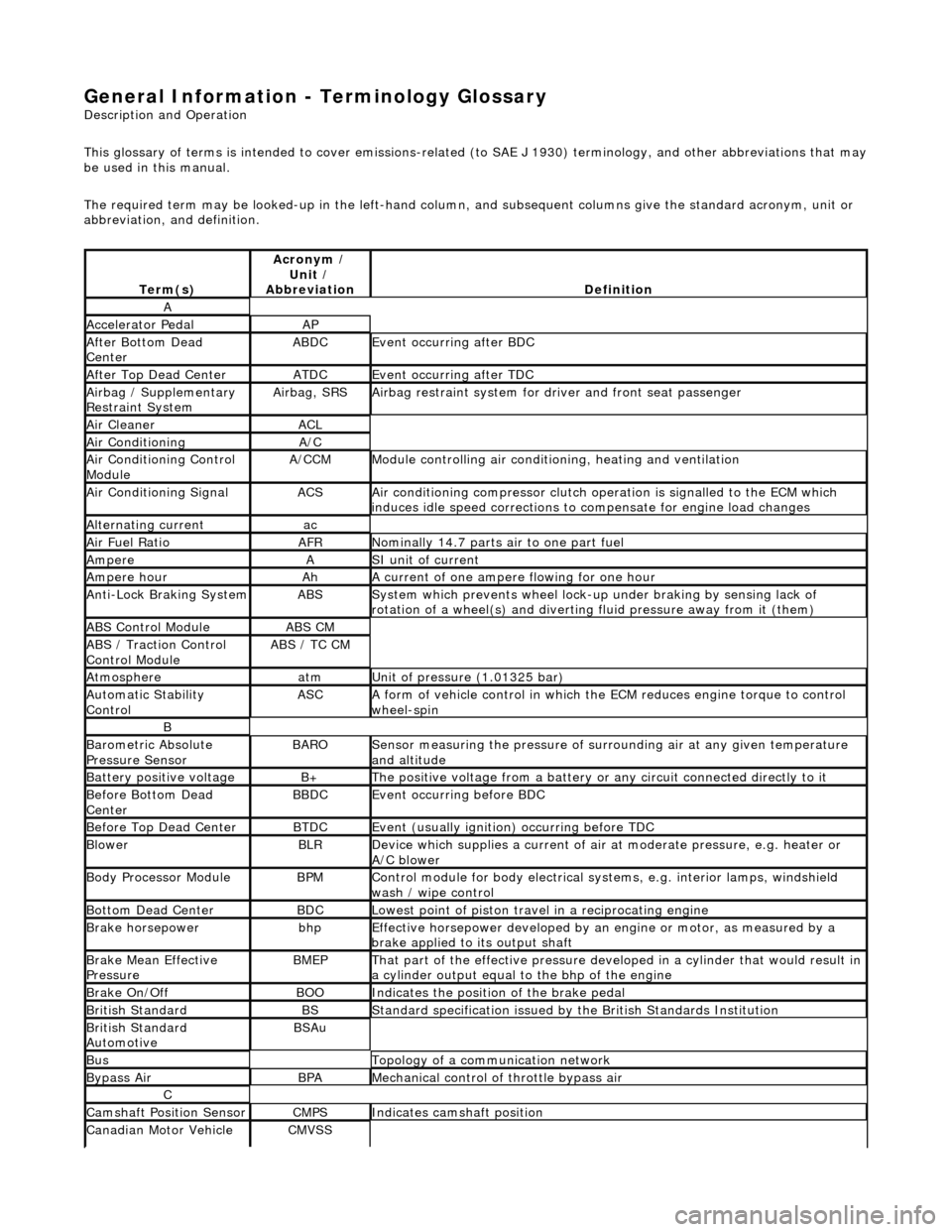
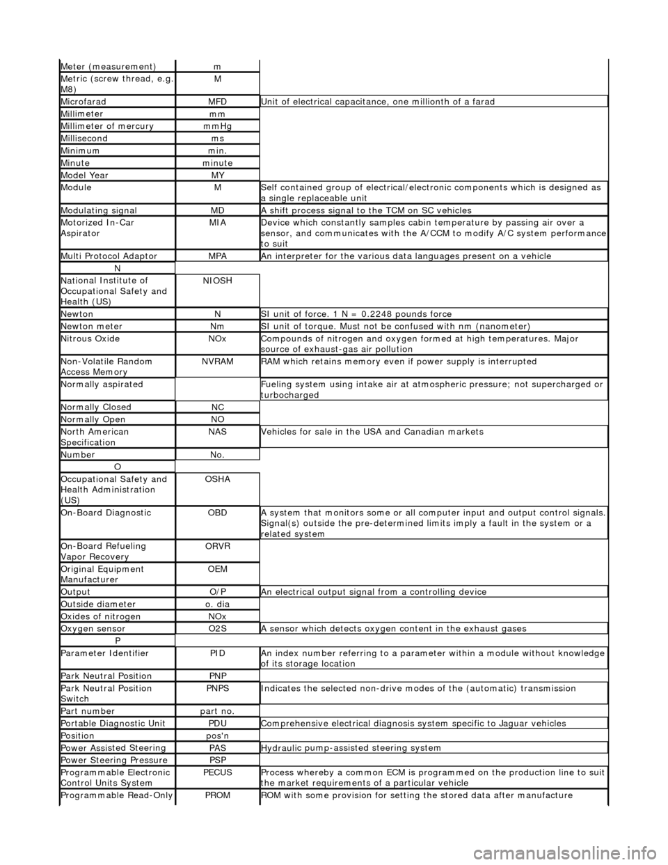
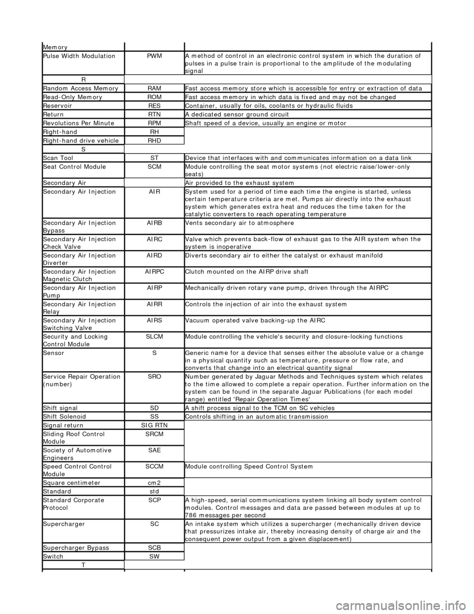
General Information - Terminology Glossary
Description an
d Operation
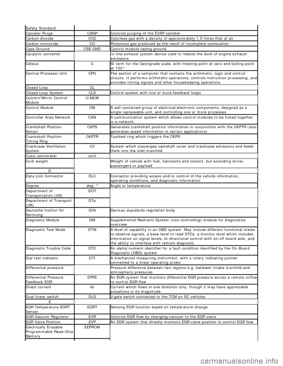
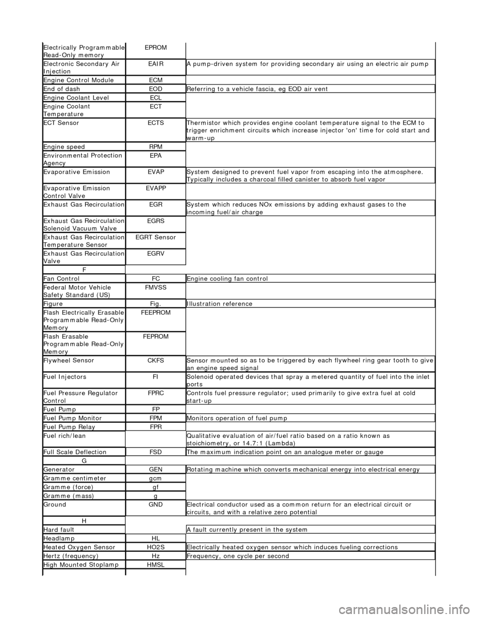
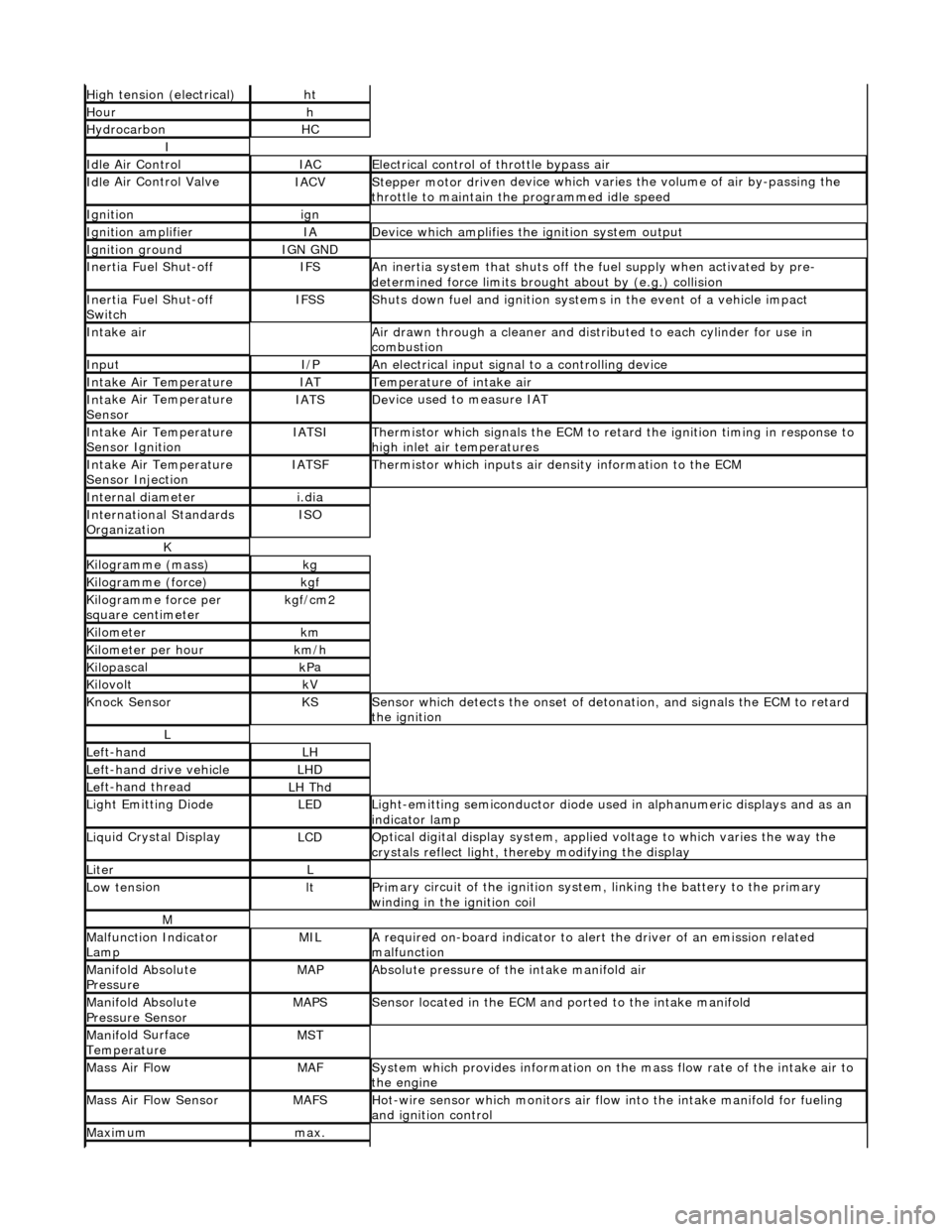
This glossary of terms is intended to cover emissions-related (to SAE J 1930) term inology, and other abbreviations that may
be used in this manual.
The required term may be looked-up in th e left-hand column, and subsequent columns give the standard acronym, unit or
abbreviation, and definition.
Te rm
(s)
Acr
ony
m /
Unit /
Abbreviation
De fi
nition
A
Accel
e
rator Pedal
AP
Af
ter Botto
m Dead
Center
ABDCEvent occurri ng after
BDC
Af
ter Top Dead CenterATDCEvent occurri ng after
TDC
Ai
rbag /
Supplementary
Restraint System
Airbag, SRSAi rbag restraint system for
dr
iver and front seat passenger
Air Cleane rACL
Air ConditioningA/C
Air Conditioning Con t
rol
Module
A/CCMModule c
ontrolling air conditioning, heating and ventilation
Air Conditioning SignalACSA
i
r conditioning compressor clutch operation is signalled to the ECM which
induces idle speed corrections to co mpensate for engine load changes
Alternating cu
rrent
ac
Ai
r Fuel R
atio
AFRN
omi
nally 14.7 parts air to one part fuel
Ampe
reASI unit of current
Ampere hourAhA current of one ampere
fl
owing for one hour
Anti-Lock Braking SystemABSS
y
stem which prevents wheel lock-up
under braking by sensing lack of
rotation of a wheel(s) and divertin g fluid pressure away from it (them)
ABS Control Mo
dule
ABS CM
ABS /
T
raction Control
Control Module
ABS / T
C CM
Atmosph
e
re
atmU
n
it of pressure (1.01325 bar)
Au
to
matic Stability
Control
ASCA form of vehicle
control
in which the ECM reduces en gine torque to control
wheel-spin
B
Baro me
tric Absolute
Pressure Sensor
BAR OSensor measuring the pressure of surr ou
nding air at any given temperature
and altitude
Bat t
ery positive voltage
B+The posi
ti
ve voltage from a battery or
any circuit connected directly to it
Before Bottom Dead
CenterBBDCEvent occurri ng before BD
C
Before Top Dead
Center
BTD
CEvent (usual ly
ignition) occurring before TDC
Blowe
rBLRDe
vice which supplies a current of air at
moderate pressure, e.g. heater or
A/C blower
Body Processor M
odule
BPMControl modu
le
for body electrical systems, e.g. interior lamps, windshield
wash / wipe control
Bott om D
ead Center
BD
CLowest poin t of piston
travel in a reciprocating engine
Brake hors
epowe
r
bhpEffecti
ve horsepower devel
oped by an
engine or motor, as measured by a
brake applied to its output shaft
Brake Mean Effective
Pres sureBME PThat p
art of the effective
pressure developed in a cyli nder that would result in
a cylinder output equal to the bhp of the engine
Brake On/ O
ff
BOOIn
dic
ates the position of the brake pedal
Br
it
ish Standard
BSStan
dar
d specification issued by the British Standards Institution
Br
it
ish Standard
Automotive
BSAu
BusTopology of a commu n
ication network
Bypass
AirBPAMechanica l
control of throttle bypass air
C
Camshaft Posit
i
on Sensor
CMPSIndi
cat
es camshaft position
Canadian Motor
V
ehicle
CMVSS
Page 43 of 2490
Safety Standard
Canister PurgeCANPControls pu
rging of the EVAP canister
Carbon dioxideCO2Colorless gas with
a density of a
pproximately 1.5 ti mes that of air
Carbon mon
oxide
COPoi
sonous gas produced as the re
sult of incomplete combustion
Case G
round
CSE GNDControl modu
le casing ground
Catal
ytic converter
In
-line exhaust system device used to reduce the level of engine exhaust
emissions
Ce
lsius
CSI ter
m for the Centigrade scale, with
freezing point at zero and boiling point
at 100°
Central
Processor Unit
CPUTh
e section of a computer that contai
ns the arithmetic, logic and control
circuits. It performs arithm etic operations, controls instruction processing, and
provides timing signals and other housekeeping operations
Cl
osed Loop
CL
Cl
osed Loop System
CLSControl
system with one
or more feedback loops
Col
umn/Mirror Control
Module
C/MC
M
Control ModuleCMA
self-contained group of electrical/electronic components, designed as a
single replaceable un it, and controlling one or more processes
Controll
er Area Network
CANA
communication system which allows control modules to be linked together
in a network.
Crankshaft Posi
tion
Sensor
CKPSGenerates crankshaft positi on informa
tion in conjunct
ion with the CKPTR (also
generates speed information in certain applications)
Crankshaft Posi
tion
Timing Ring
CKPT
R
Toothe
d ring which
triggers the CKPS
Crankcase Ventila
tion
System
CVSys
tem which scavenges camshaft cover and crankcase emissions and feeds
them into the inlet manifold
Cubic ce nt
imeter
cm
3
Curb weightWe
ight of vehicle with fuel, lubrican
ts and coolant, but excluding driver,
passengers or payload
D
Dat
a Link Connector
DLCConne
ctor providing access and/or control of the vehicle information,
operating conditions, and diagnostic information
De
gree
deg, °Angle or tempe
rature
D
epartment of
Transportation (US)
DO
T
D
epartment of Transport
(UK)
DTp
De
utsche In
stitut für
Normung
DINGerman stand
ards regulation body
Di
agnostic Module
DMSuppl
emental Restraint System (non-c
ontrolling) module for diagnostics
overview
Di
agnostic Test Mode
DTMA le
vel of capability in an OBD system.
May include different functional states
to observe signals, a base level to re ad DTCs, a monitor level which includes
information on signal levels, bi-directional control with on /off board aids, and
the ability to interface with remote diagnosis
Diagnostic Trouble CodeDTCAn al
pha/numeric identifier for a fault
condition identified by the On-Board
Diagnostic (OBD) system
D
ial test indicator
DTIA mechan
ical measuring
instrument, with a rotary indicating pointer
connected to a linear operating probe
D
ifferential pressure
Pressure di
fference betwee
n two regions e.g. between intake manifold and
atmospheric pressures
D
ifferential Pressure
Feedback EGR
DP
FE
An
EGR system that monito
rs differential EGR pressure across a remote orifice
to control EGR flow
D
irect current
dcCurrent which f
lows in on
e direction only, though it may have appreciable
pulsations in its magnitude
Du
al linear switch
DLSJ
-gate switch connected to the TCM on SC vehicles
E
EGR
Temperature EGRT
Sensor
EGRTSens
ing EGR function based on temperature change
EGR Vacu
um Regulator
EVRControls EGR
flow by changi
ng vacuum to the EGR valve
EGR Valve
Position
EVPAn EGR
system that direct
ly monitors EGR valve position to control EGR flow
Electrically E
rasable
Programmable Read-Only
Memory
EEP
ROM
Page 44 of 2490
Electrically Programmable
R
ead-Only memory
EPROM
Ele
c
tronic Secondary Air
Injection
EAIRA p
ump-driven system for providing seco
ndary air using an electric air pump
Engine C
ontrol Module
ECM
End of dashEODR
e
ferring to a vehicle fascia, eg EOD air vent
Engine
C
oolant Level
ECL
Engine
C
oolant
Temperature
ECT
ECT Sen s
or
ECTSTherm
i
stor which provides engine coolant temperature signal to the ECM to
trigger enrichment circuits which increase injector 'on' time for cold start and
warm-up
Engine s
peed
RP
M
Environ m
ental Protection
Agency
EPA
Evaporative EmissionEVAPSy stem designed to prevent fu
el vapor from escaping into the atmosphere.
Typically includes a charcoal filled canister to absorb fuel vapor
Evaporative Emission
Control ValveEVAPP
Exhaust G
as Recirculation
EGRSys
t
em which reduces NOx emissions by adding exhaust gases to the
incoming fuel/air charge
Exhaus t G
as Recirculation
Solenoid Vacuum Valve
EGRS
Exhaus t G
as Recirculation
Temperature Sensor
EGRT Sen s
or
Exhaus
t G
as Recirculation
Valve
EGRV
F
F a
n Control
FCEngine
cooling fan control
F
e
deral Motor Vehicle
Safety Standard (US)
FMV S
S
Fi
gur
e
Fi
g.Illustrati
on reference
Flash
E
lectrically Erasable
Programmable Read-Only
Memory
FEE PR
OM
Flash
E
rasable
Programmable Read-Only
Memory
FEP R
OM
Flywhee
l
Sensor
CKFSSens
or moun
ted so as to be
triggered by each flywheel ring gear tooth to give
an engine speed signal
Fue l
Injectors
FISol
e
noid operated devices that spray a metered quantity of fuel into the inlet
ports
F u
el Pressure Regulator
Control
FP RCControls fuel pressure regu l
ator; used primarily to
give extra fuel at cold
start-up
Fue l
Pump
FP
Fue
l
Pump Monitor
FP
MMonitors operation of fuel pump
Fue l
Pump Relay
FP
R
Fu
el rich/lean
Q
u
alitative evaluation
of air/fuel ratio based on a ratio known as
stoichiometry, or 14.7:1 (Lambda)
F u
ll Scale Deflection
FSDTh
e
maximum indication point on
an analogue meter or gauge
G
Gene
rator
GENRot
a
ting machine which converts mechanical energy into electrical energy
G
r
amme centimeter
gcm
Gramm
e
(force)
gf
Gramm
e
(mass)
g
GroundGNDEle
c
trical conductor used
as a common return for an electrical circuit or
circuits, and with a relative zero potential
H
Hard f a
ult
A
fau
lt currently present in the system
HeadlampHL
Heat
ed Oxygen
Sensor
HO2SElectrically
h
eated oxygen sensor which induces fueling corrections
Hertz (frequency)HzFrequ
e
ncy, one cycle per second
High
Moun
ted Stoplamp
HMSL
Page 45 of 2490
High
tension (electrical)
ht
Hourh
Hydro
carbon
HC
I
Idl
e Air Control
IACEl
ectrical control of throttle bypass air
Idl
e Air Control Valve
IACVStepper motor dri
ven device which vari
es the volume of air by-passing the
throttle to maintain the programmed idle speed
Ignitionign
Ignition am
plifier
IAD
evice which amplifies the i
gniti
on system output
Ignition groundIGN GND
In
ertia Fuel Shut-off
IFSAn
inertia system that shuts off the fuel supply when activated by pre-
determined force limits brough t about by (e.g.) collision
In
ertia Fuel Shut-off
Switch
IFSSShut
s down fuel and ignition systems in the event of a vehicle impact
Inta
ke air
Air drawn t
hrough a cleaner and distri
buted to each cylinder for use in
combustion
InputI/PAn
electrical input signal to a controlling device
Inta
ke Air Temperature
IATTem
perature of intake air
Inta
ke Air Temperature
Sensor
IATSDe
vice used to measure IAT
Inta
ke Air Temperature
Sensor Ignition
IATSITherm
istor which signals the ECM to retard
the ignition timing in response to
high inlet air temperatures
Inta
ke Air Temperature
Sensor Injection
IATSFTher
mistor which inputs air density information to the ECM
Internal diameteri.
dia
Inte
rnational Standards
Organization
ISO
K
Kilogramme (mass)kg
Kilogram
me (force)
kg
f
Ki
logramme force per
square centimeter
kg
f/cm2
Kilom
eter
km
Ki
lometer per hour
km
/h
Kilopasc
al
kP
a
KilovoltkV
Knock
Sensor
KSSens
or which detects the onset of detonation, and signals the ECM to retard
the ignition
L
Le
ft-hand
LH
Left-hand drive veh
icle
LHD
Le
ft-hand thread
LH Thd
Ligh
t Emitting Diode
LEDLigh
t-emitting semiconductor diode used
in alphanumeric displays and as an
indicator lamp
Liqu
id Crystal Display
LCDOp
tical digital display system, applied voltage to which varies the way the
crystals reflect light, thereby modifying the display
LiterL
Low ten
sion
ltPrim
ary circuit of the ignition system, linking the battery to the primary
winding in the ignition coil
M
Malfu
nction Indicator
Lamp
MILA
required on-board indicator to aler
t the driver of an emission related
malfunction
Mani
fold Absolute
Pressure
MAPAbsolute pressure o
f the intake manifold air
Mani
fold Absolute
Pressure Sensor
MAPSSensor loca
ted in the ECM and
ported to the intake manifold
Manifol
d Surface
Temperature
MST
Mass Ai
r Flow
MAFSy
stem which provides inform
ation on the mass flow rate of the intake air to
the engine
Mass Ai
r Flow Sensor
MAFSHot-wi
re sensor which monitors air flow
into the intake manifold for fueling
and ignition control
Maxim
um
max.
Page 46 of 2490
Meter (measurement)m
Me
tric (screw thread, e.g.
M8)
M
MicrofaradMFDUni t
of electrical capacitance, one millionth of a farad
Mi
ll
imeter
mm
Mi
ll
imeter of mercury
mm
Hg
Mill
isecond
ms
Min
i
mum
mi
n.
Min u
te
minut
e
Model YearMY
ModuleMSelf
contained group of electrical/electronic components which is designed as
a single replaceable unit
Modulating signalMDA sh
ift process signal to the TCM on SC vehicles
Motorized In
-Car
AspiratorMIAD e
vice which constantly samples cabi
n temperature by passing air over a
sensor, and communicates with the A/ CCM to modify A/C system performance
to suit
Mult i Prot
ocol Adaptor
MPAAn i
n
terpreter for the various data
languages present on a vehicle
N
Nati
onal Institute of
Occupational Safety and
Health (US)
NIO S
H
Ne
wto
n
NSI unit of force. 1
N = 0.224
8 pounds force
Ne
wto
n meter
NmSI unit of torque. Must not be
co
nfused with nm (nanometer)
Ni
tr
ous Oxide
NO
xCompounds of nit rogen and oxygen fo rmed at high temperatures. Major
sourc
e of exhaust-gas air pollution
No
n
-Volatile Random
Access Memory
NVR A
M
R
A
M which retains memory even
if power supply is interrupted
Normal
ly aspirated
F
u
eling system using intake air at atmo
spheric pressure; not supercharged or
turbocharged
N ormal
ly Closed
NC
N
o
rmally Open
NO
No
r
th American
Specification
NASVehicles f or sal
e in the USA and Canadian markets
Nu
mbe
r
No
.
O
Oc
cupational Safety and
Health Administration
(US)
OS H
A
O
n
-Board Diagnostic
OB
DA system that moni
tors some or all co
mputer input and output control signals.
Signal(s) outside the pre-de termined limits imply a fault in the system or a
related system
O n
-Board Refueling
Vapor Recovery
OR V
R
O
riginal
Equipment
Manufacturer
OE M
Outp
ut
O/
PAn electrical o u
tput signal from a controlling device
Ou
ts
ide diameter
o.
d
ia
O
xides of
nitrogen
NO
x
Oxygen senso
r
O2
SA s
ensor which detects oxygen content in the exhaust gases
P
Parameter Identifi
erPIDAn in
dex number referring to a parame
ter within a module without knowledge
of its storage location
Park N e
utral Position
PN
P
Park N e
utral Position
Switch
PN PSIndic
ates the selected non-drive modes of the (automatic) transmission
Part numberpart no.
Portable Diag
nostic Un
it
PD
UCompre hen
sive electrical diagnosis system specific to Jaguar vehicles
Posi
ti
on
po
s'n
Power As si
sted Steering
PASHydraul
i
c pump-assisted steering system
Power Steer
i
ng Pressure
PSP
Programmable Elect
r
onic
Control Units System
PECU SProcess whereb y
a common ECM is progra
mmed on the production line to suit
the market requirements of a particular vehicle
Programmable Read-O
nly
PROMRO
M with some provision for setting
the stored data after manufacture
Page 47 of 2490
Mem
ory
Pulse Width ModulationPW
M
A
method of control in an electronic co
ntrol system in which the duration of
pulses in a pulse train is proportional to the amplitude of the modulating
signal
R
Ran
dom Access Memory
RAMF
ast access memory store which is accessible for entry or extraction of data
Re
ad-Only Memory
RO
M
F
ast access memory in which data
is fixed and may not be changed
Re
servoir
RESContaine
r, usually for oils,
coolants or hydraulic fluids
Re
turn
RTNA
dedicated sensor ground circuit
R
evolutions Per Minute
RP
M
Shaft speed o
f a device, us
ually an engine or motor
R
ight-hand
RH
Right-hand drive veh
icle
RHD
S
Scan T
ool
STDe
vice that interfaces with and comm
unicates information on a data link
Se
at Control Module
SCMModule
controlling the seat motor systems (not electric raise/lower-only
seats)
Secon
dary Air
Air pro
vided to the exhaust system
Secon
dary Air Injection
AIRSy
stem used for a period of time each
time the engine is started, unless
certain temperature criter ia are met. Pumps air directly into the exhaust
system which generates extra heat and reduces the time taken for the
catalytic converters to reach operating temperature
Secon
dary Air Injection
Bypass
AIRBVents secon
dary air to atmosphere
Secon
dary Air Injection
Check Valve
AIRCValve wh
ich prevents back-flow of exhaust gas to the AIR system when the
system is inoperative
Secon
dary Air Injection
Diverter
AIRDD
iverts secondary air to either
the catalyst or exhaust manifold
Secon
dary Air Injection
Magnetic Clutch
AIRP
C
Clu
tch mounted on the AIRP drive shaft
Secon
dary Air Injection
Pump
AIRPMe
chanically driven rotary vane
pump, driven through the AIRPC
Secon
dary Air Injection
Relay
AIRRCont
rols the injection of air into the exhaust system
Secon
dary Air Injection
Switchin
g Va
lve
AIRSV
acuum operated valve backing-up the AIRC
Secu
rity and Locking
Control Module
SLCMModul
e controlling the vehicle's security and closure-locking functions
SensorSGeneri
c name for a device
that senses either the absolute value or a change
in a physical quantity su ch as temperature, pressure or flow rate, and
converts that change into an electrical quantity signal
Servic
e Repair Operation
(number)
SRONu
mber generated by Jaguar Methods
and Techniques system which relates
to the time allowed to complete a repair operation. Further information on the
system can be found in the separate Jaguar Publications (for each model
range) entitled 'Repair Operation Times'
Shif
t signal
SDA
shift process signal to the TCM on SC vehicles
Shif
t Solenoid
SSControls shi
fting in an automatic transmission
Si
gnal return
SIG RTN
Slidin
g Roof Control
Module
SRCM
Society of Automotive
Engineers
SAE
Speed
Control Control
Module
SCCMModule con
trolling Speed Control System
Square c
entimeter
cm
2
Stan
dard
std
Stan
dard Corporate
Protocol
SCPA
high-speed, serial communications system linking all body system control
modules. Control messages and data ar e passed between modules at up to
786 messages per second
SuperchargerSCAn in
take system which utilizes a supercharger (mechanically driven device
that pressurizes intake air, thereby in creasing density of charge air and the
consequent power output from a given displacement)
Supercharger
Bypass
SCB
SwitchSW
T
Page 396 of 2490
Parking Brake and Actuation - P
arking Brake Control
Re
mo
val and Installation
Remov
a
l
W
A
RNING: BRAKE DUST, IF INHALED CAN DAMAGE YOUR
HEALTH. ALWAYS REMOVE BRAKE DUST USING A VACUUM
BRUSH. DO NOT USE A COMPRESSED-AIR LINE TO DISPERSE BRAKE DUST INTO THE ATMOSPHERE.
CAUTION: Replacement of nuts and bolts: Various thread-locking devices are used on nuts and bolts throughout the
vehicle. These devices restrict the number of times a nut or bolt can be used. See section 100-00 for information.
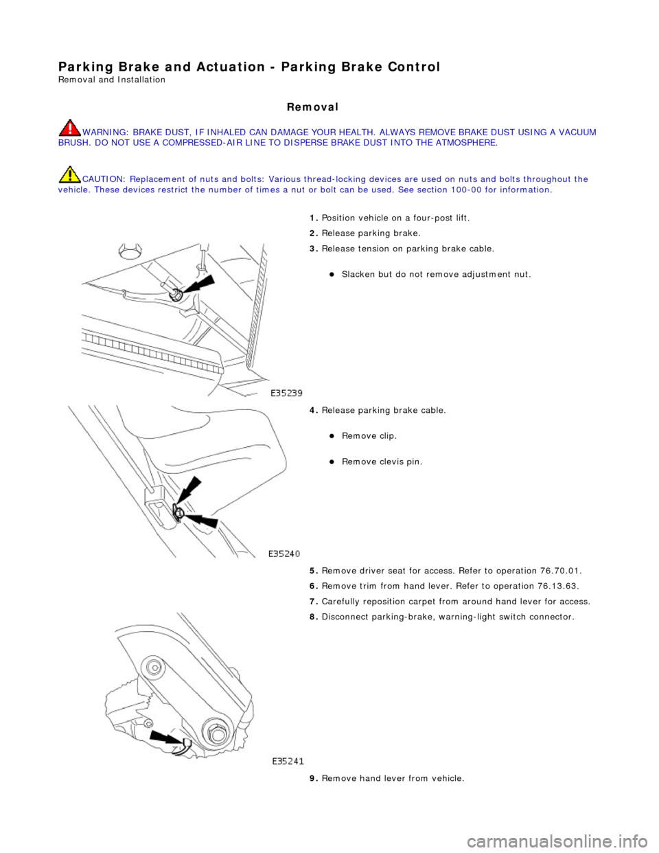
1. Position vehi cl
e on a four-post lift.
2. Release parking brake.
3. Releas
e tension on parking brake cable.
Slacken bu
t do not remove adjustment nut.
4. Releas
e parking brake cable.
Remo
ve clip.
Re
mo
ve clevis pin.
5. Remove driver seat for access . Refer to operation 76.70.01.
6. Remove trim from hand lever. Refer to operation 76.13.63.
7. Carefully reposition carpet from around hand lever for access.
8. Disconnect park ing-br
ake, warning-light switch connector.
9. Remove hand lever from vehicle.
Page 407 of 2490

The t
andem master cylinder contains two in
dependent pistons, fluid pressure to each brake circuit is controlled by its own
individual piston. Brake fluid is supplied to the master cylinder by the reservoir, which is divided into two sections to preve nt
total fluid loss should one of the circuits fail. A port situated at the bottom of each section of the reservoir supplies the f luid
to each piston.
The fluid reservoir has a fluid-le vel indicator switch installed, which operates when the fluid level is low, causing the brake
fluid level warning-lamp to illuminate.
Bra
ke Caliper
The brake
calipers are of the single piston
type. The caliper carrier, which is secured to the vertical link by two bolts, carr ies
the single-piston caliper housing. The cali per housing is secured to the caliper carrier by two guide-pins and an anti-rattle
spring. When the brakes are applied, the caliper-housing piston pushes the brake pad in front of it, to wards the brake disc.
This movement forces the calipe r housing to move along the guid e-pins, in the opposite direction of the piston, to apply the
second brake pad.
Br
embo Brake Caliper
The four
cylinder brake caliper is rigidly attached to the vert
ical link via an anchor bracket. The caliper is a split assembly
with each side of the caliper, housing two pistons. The two-pairs of opposed pistons act direct ly on the brake pads mounted
one each side of the disc.
Mast
er Cylinder and Reservoir
Page 430 of 2490
Anti-Lock Control - Anti-Lock Control
Description and Operation
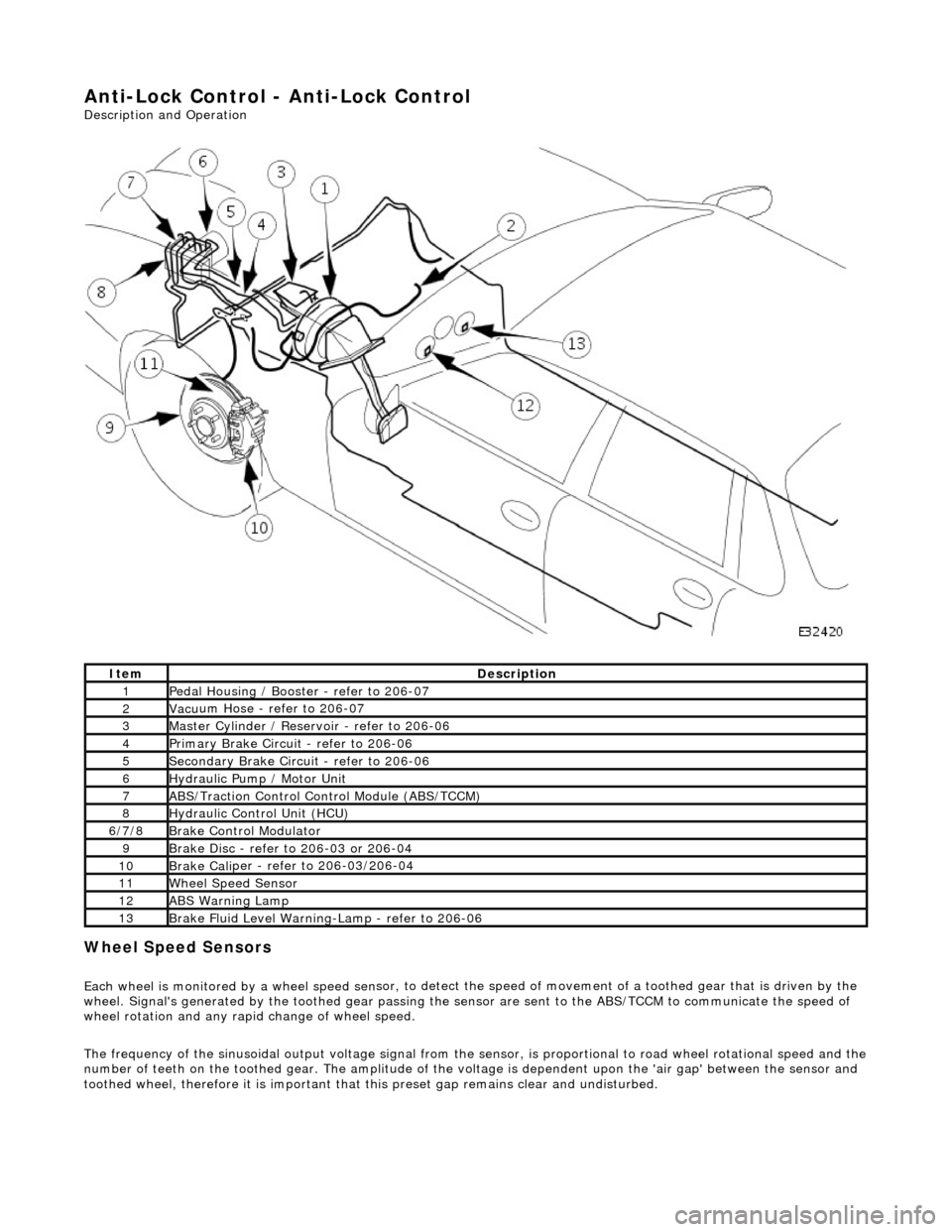
Wheel Spe
ed Sensors
Each
wheel is monitored by a wheel speed se n
sor, to detect the speed of movement of
a toothed gear that is driven by the
wheel. Signal's generate d by the toothed gear passing th e sensor are sent to the ABS/TCCM to communicate the speed of
wheel rotation and any rapid change of wheel speed.
The frequency of the sinusoidal output voltag e signal from the sensor, is proportional to road wheel rotational speed and the
number of teeth on the toothed gear. The amplitude of the volt age is dependent upon the 'air gap' between the sensor and
toothed wheel, therefore it is important that this preset gap remains clear and undisturbed.
Ite
m
De
scr
iption
1Pe
dal Housi
ng / Booster - refer to 206-07
2Vac
u
um Hose - refer to 206-07
3Mas
t
er Cylinder / Reservoir - refer to 206-06
4Pri
m
ary Brake Circuit - refer to 206-06
5Sec
ondary Brake Circuit - refer to 206-06
6Hydraulic
Pump / Motor Unit
7ABS/Traction
Control Control Module (ABS/TCCM)
8Hydraulic Cont
rol Unit (HCU)
6/
7/
8
Br
ak
e Control Modulator
9Brake
Di
sc - refer to 206-03 or 206-04
10Brake
Cali
per - refer to 206-03/206-04
11Wh
ee
l Speed Sensor
12ABS Warning Lamp
13Brake
Fl
uid Level Warning-Lamp - refer to 206-06
Page 432 of 2490
It is a reciprocating two
-circuit pu
mp in which one brake circuit is as signed to each pump circuit.
It supplies th
e fluid pressure and vo
lume to supply the brake circuits under ABS and Traction control.
The pump is driven by an electri
c motor, with the pump
housing incorporating two lo w pressure accumulators and
damping chambers for each brake circuit.
The ac cu
mulator stores the pressure and smooths out the output pu
lses from the pump.
ABS Warning Lamp
The sys
tem will be set in a fail-safe mode if a problem is de
tected; a warning lamp on the instrument panel will notify the
driver there is a problem.
Anti-Lock Braking Sy
stem (ABS)
The AB
S components are combined with
an hydraulic booster and a tandem master cylinder to provide a two circuit braking
system. The system comprises, four wheel speed sensor s, a brake control modulator and an ABS warning lamp.
Should a wheel start to lock-up during braking a signal tr ansmitted from the wheel speed sensor to the brake control
modulator will start the hydraulic pump. The brake control modula tor will close the input valve of the line connected to the
locked-wheel to stop any increase in fluid pressure to the br ake caliper. If this fails to prevent the wheel locking, the
pressure in the caliper will be decreased by opening the return valve until th e wheel starts accelerating again. The fluid
pressure from the return va lve is directed into the low pressure accumulator, housed in the pump.
From the low pressure accumulator, fl uid is pumped through the damping cham ber to the brake master cylinder. The
pressure to the brake caliper will then be increased in small steps to maintain maximum adhesion between the tire and road
surface. This is achieved by closing the return valve, and opening the input valve and using the hydraulic pump to increase
the pressure.
Although the system senses all four wheels independently, the rear wheels are regulated as a pair. If a sensor on a rear
wheel detects a wheel decelerating rapidly, then the fluid pressure to both wheels is reduced. The fluid pressure is then
dictated by the wheel having the lowe st adhesion with the road surface.
The ABS system will be set in a fail-safe mode if a problem is detected; a warn ing lamp on the instrument panel will notify
the driver there is a problem. The brake system will still operate conventionally and with the same standard of performance
as a vehicle not equipped with ABS.
Automa tic Stability Control (ASC)
Th
e ASC utilizes the ABS sensing arrangement to provide the maximum traction force to propel the vehicle.
The ASC is switched on when the engine is started. The system can be switched off by pressing the 'ASC OFF' (the switched
is marked 'TRAC OFF' on vehicles fitted with traction control). The switch, which is situated in the center console switchpack,
lights up to warn that the system is sw itched off. An 'ASC' amber warning light flashes on the instrument panel when the
system detects a spinning wheel.
The ASC system uses engine intervention to reduce the torque delivered to the drive wheels to prevent them spinning.
Engine torque is re duced in three ways:
The
throttle is moved towards the closed position.
The ignition is retarded. F
u
el is cut-off at the cylinder injectors.
Wheel spin is detected by the wheel sp eed sensors and communicated to the AB S/TCCM. The ABS/TCCM uses information
from the controller area network (CAN) to calculate the torque that the engine should produce to stop the wheel spinning.
Torque reductions are then requested from the engine control module (ECM ) through the CAN. The throttle is then
positioned to provide the target torque, which has been calculated to prevent wheel spin. During the transient phase of
torque reduction the fuel is cut-off and th e ignition retarded Both the fuel cut-off an d ignition retard will be restored to
normal when the throttle is set to its new position.
The ASC uses a brake control modulator with six solenoid va lves: three normally open inlet valves and three normally