air control JAGUAR X308 1998 2.G Workshop Manual
[x] Cancel search | Manufacturer: JAGUAR, Model Year: 1998, Model line: X308, Model: JAGUAR X308 1998 2.GPages: 2490, PDF Size: 69.81 MB
Page 2246 of 2490
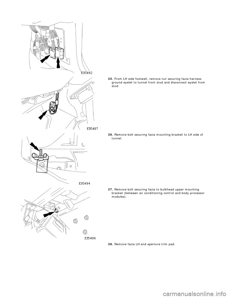
35. From LH side footwell, remove nut securing facia harness
ground eyelet to tunnel front stud and disconnect eyelet from
stud.
36. Remove bolt securing facia moun ting bracket to LH side of
tunnel.
37. Remove bolt securing facia to bulkhead upper mounting
bracket (between air conditioni ng control and body processor
modules).
38. Remove facia LH end aperture trim pad.
Page 2275 of 2490

Handles, Locks, Latches and Entry Systems - Door Lock Control Switch
Removal and Installation
Removal
1. Disconnect battery ground cable; refer to 86.15.19.
2. Remove center console veneer panel; refer to 76.47.26.
3. Displace radio for access; refer to 86.50.03.
4. Disconnect air conditioning control module flying lead
connector (blue) from harness connector located at side of 'J'
gate.
5. Displace air conditioning switch module / center console
switch module assembly.
Remove screw.
Reposition assembly for access to connector.
6. Remove air conditioning switch module / center console switch
module assembly.
Disconnect center console switch module harness
connector.
Remove assembly.
Page 2307 of 2490
cooling duct.
The windshield washer is operated by pressing the button at the end of the wiper control stalk switch. Pressing and
releasing the button operates the washer for 1 to 1.4 seconds and the wiper completes three sweeps. An optional drip wipe
function adds a further sweep of the wiper after a 4 second delay, to clear residual fluid from the windshield. If the button is
held depressed, the washer and wiper will operate continuous ly for up to 20 seconds. When the button is released, the
wiper will again complete three further sweeps.
Headlamp Powerwash
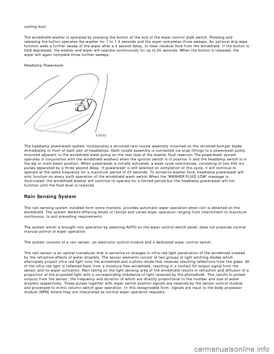
The headlamp powerwash system incorporates a chromed twin nozzle assembly mounted on the chromed bumper blade
immediately in front of each pair of he adlamps. Each nozzle assembly is connected via snap fittings to a powerwash pump
mounted adjacent to the windshield wash pump on the rear face of the washer fluid reservoir.The powerwash system
operates in conjunction with the windshield washers when the ignition switch is in position II and the headlamp switch is in
the dip or main beam position. When powerwash is initially activated, a wash cycle commences, consisting of two 400 ms
pulses separated by a three second delay. If powerwash is still selected on completion of this cycle, it will continue to
operate at the same frequency for a maximum period of 20 se conds. To conserve washer fluid, headlamp powerwash will
only function on every sixth operation of the windshie ld wash switch.When the 'WASHER FLUID LOW' message is
illuminated, the windshield washer will continue to operat e for a limited period but the headlamp powerwash will not
function until the fluid level is restored.
Rain Sensing System
The rain sensing system installed form so me markets, provides automatic wiper operation when rain is detected on the
windshield. The system detects differing le vels of rainfall and varies wiper operation ranging from intermittent to maximum
continuous, to suit prevailing requirements.
The system which is brought into operation by selecting AUTO on the wiper control switch bezel, does not preclude normal
manual control of wiper operation.
The system consists of a rain sensor, an electronic control module and a dedicated wiper control switch.
The rain sensor is an optical transducer that is sensitive to changes in infra-red light penetration of the windshield created
by the refractive effects of water drople ts. The sensor elements consist of two groups of light emitting diodes which
alternately project infra-red light onto th e windshield and a photo-diode that receiv es resulting reflections from the glass. A ll
of the infra-red light is reflected back from a moisture-free windshield, resulting in a contact 5V output signal from the
sensor and no wiper activation. Rain falling on the light sensing area of the wi ndshield results in refraction and diffusion of a
proportion of the projected light with a corresponding imbalance of light received by the photodiode. This results in pulsed
outputs from the sensor, the frequency and duration of which are directly proportional to the number and size of water
droplets respectively. These pulses together with wiper switch position signals are received by the sensor control module
and processed to mimic column switch gear operation. In this recognisable form, signals are input to the body processor
module (BPM) where they are interprete d as normal wiper operation requests.
Page 2369 of 2490

Supplemental Restraint System - Air Bag Supplemental Restraint System
(SRS)
Description and Operation
Supplementary Restraint Air Bag System
Airbag/SRS units provided for driver and fro nt seat passemger protection, are installed in the center of the steering wheel,
the passenger side fascia and the oute r wing of each front seat. A single point sensing unit (SPS) mounted on the
transmission tunnel, below the ra dio, provides fully electronic impact sensing, control and diagnostics for the front airbags
Deployment of each side airbag is initia ted by a side impact sensing module (SISM) installed in the adjacent 'B' post. Each
SISM senses and electronically processes a crash pulse and if this exceeds the 'must fire' threshold, transmits a fire signal
to the SPS unit. The SPS unit monitors wh ole vehicle motion and on confirmation of a crash condition, transmits a firing
current pulse to the appropriate airbags. In the event of a side only impact, the SPS will send a current pulse to the airbag
on the struck only. Neither th e non-struck side airbag nor the frontal restraint system will be deployed under these
conditions. The airbag system can only be activated wh en the ignition switch is in position II or III.
Side Air Bags
Page 2371 of 2490
Supplemental Restraint System - Air Bag Control Module
Removal and Installation
Removal
Installation
1.
WARNING: FOLLOWING DISCONNECTION OF THE
BATTERY, A PERIOD OF AT LEAST ONE MINUTE MUST BE
ALLOWED TO ELAPSE BEFORE ANY WORK IS CARRIED OUT ON
AN AIR BAG SYSTEM COMPONENT.
Remove battery cover and disc onnect ground cable from
battery terminal. Refer to 86.15.19.
2. Remove 'J' gate surroun d. Refer to 76.25.24.
3. Remove centre console veneer panel. Refer to 76.47.26.
4. Remove radio. Re fer to 86.50.03.
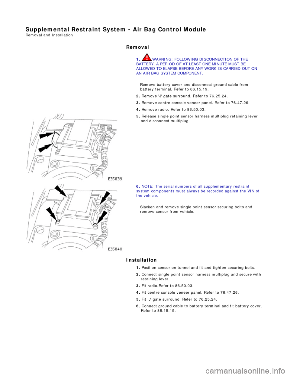
5. Release single point sensor ha rness multiplug retaining lever
and disconnect multiplug.
6. NOTE: The serial num bers of all supplementary restraint
system components must always be recorded against the VIN of
the vehicle.
Slacken and remove single point sensor securing bolts and
remove sensor from vehicle.
1. Position sensor on tunnel and fit and tighten securing bolts.
2. Connect single point sensor harn ess multiplug and secure with
retaining lever.
3. Fit radio.Refer to 86.50.03.
4. Fit centre console veneer panel. Refer to 76.47.26.
5. Fit 'J' gate surround. Refer to 76.25.24.
6. Connect ground cable to battery terminal and fit battery cover.
Refer to 86.15.15.
Page 2381 of 2490
The body is pre-treated to ensure high resistance to corrosion and stone chip dama ge. Prior to the first major pre-treatment process, the body shell is high-pressure washed to remove any metal dust and residual oil.
The first major pre-treatment process consists of phosphate and electro-paint deposition, which together with zinc coating,
forms the basis of the corrosion protection. This process includes high pressure knock-off, alkali de-greasing, zinc phosphate
conversion of body steel (dissolving iron and coating with zinc phosphate crystals), trivalent chrome rinsing and
demineralized water rinsing, seal ing all chemicals and impurities.
Both dip and spray techniques are employed and the bodies are submerged to the waistline during the first and third rinses
of the main phosphate clean. Chemical strengths and soluti on temperatures are continuously monitored and accurately
controlled throughout the process.
An 80% water primer is then cathodic elec tro-deposition applied to the thoroughly cleansed bodies in a uniform 'sag-free'
film 18 to 32 micron thick. Optimum durabi lity of the electroprimer is achieved by finally curing in a stoving oven at 165 °C
for a period of 20 minutes.
All underbody seams of the fully primed bo dies are then manually sealed, to prevent water and dust ingress into the vehicle
and to enhance corrosion protection.
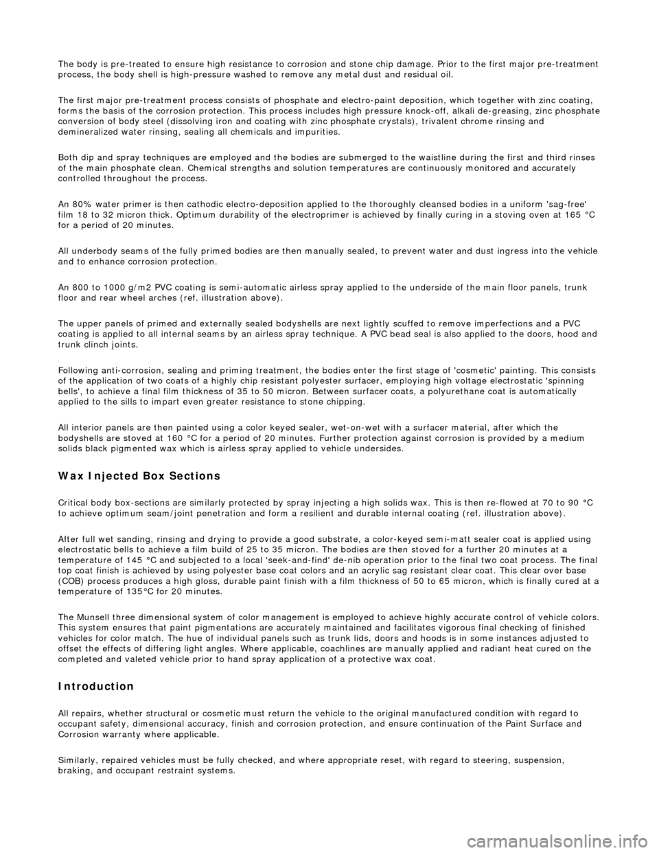
An 800 to 1000 g/m2 PVC coating is semi-automatic airless sp ray applied to the underside of the main floor panels, trunk
floor and rear wheel arches (ref. illustration above).
The upper panels of primed and external ly sealed bodyshells are next lightly scuffed to remove imperfections and a PVC
coating is applied to all internal seams by an airless spray technique. A PVC bead seal is also applied to the doors, hood and
trunk clinch joints.
Following anti-corrosion, sealing and primin g treatment, the bodies enter the first stage of 'cosmetic' painting. This consists
of the application of two coats of a highly chip resistant po lyester surfacer, employing high voltage electrostatic 'spinning
bells', to achieve a final film thickness of 35 to 50 micron. Between surfacer coats, a polyurethane coat is automatically
applied to the sills to impart even greater resistance to stone chipping.
All interior panels are then painted us ing a color keyed sealer, wet-on-wet wi th a surfacer material, after which the
bodyshells are stoved at 160 °C for a period of 20 minutes. Further protection agai nst corrosion is provided by a medium
solids black pigmented wax which is airless spray applied to vehicle undersides.
Wax Injected Box Sections
Critical body box-sections are si milarly protected by spray injecting a high solids wax. This is then re-flowed at 70 to 90 °C
to achieve optimum seam/joint penetratio n and form a resilient and durable internal coating (ref. illustration above).
After full wet sanding, rinsing and drying to provide a good su bstrate, a color-keyed semi-matt sealer co at is applied using
electrostatic bells to achieve a film build of 25 to 35 micron . The bodies are then stoved for a further 20 minutes at a
temperature of 145 °C and subjected to a local 'seek-and-find' de -nib operation prior to the final two coat process. The final
top coat finish is achieved by using poly ester base coat colors and an acrylic sag resistant clear coat. This clear over base
(COB) process produces a high gloss, durabl e paint finish with a film thickness of 50 to 65 micron, which is finally cured at a
temperature of 135°C for 20 minutes.
The Munsell three dimensional system of color management is em ployed to achieve highly accurate control of vehicle colors.
This system ensures that paint pigmentations are accurately maintained and facilitates vigorous final checking of finished
vehicles for color match. The hu e of individual panels such as trunk lids, doors and hoods is in some instances adjusted to
offset the effects of differing light angles. Where applicable, coachlines are manually applied and radiant heat cured on the
completed and valeted vehicle prior to hand spray applic ation of a protective wax coat.
Introduction
All repairs, whether structural or cosmetic must return the vehicle to the original manufactured condition with regard to
occupant safety, dimensional accuracy, fi nish and corrosion protection, and ensure continuation of the Paint Surface and
Corrosion warranty where applicable.
Similarly, repaired vehicles must be fu lly checked, and where appropriate reset, with regard to steering, suspension,
braking, and occupant restraint systems.
Page 2382 of 2490
Health and Safety
It is the duty of both employer and employee to ensure safe working conditions and practices. Correct safety procedures
and equipment must be applied to any potential hazards that are notified, or identified by an operator.
Employees must observe local legislation go verning working conditions and practices at all times and must always act in a
responsible manner in the workplace. In the event of personal injury resulting from any workshop activity, medical help
should be obtained as soon as poss ible. Self-treatment other than by first aid, should not be attempted.
WARNING: READ AND UNDERSTAND WORKING PRACTICE S CONCERNING CLIMATE CONTROL SYSTEMS, SECTION
412, WITH SPECIAL REGARD TO: REFRIGERANT MUST NEVE R BE DIRECTLY VENTED TO ATMOSPHERE. ALWAYS USE
JAGUAR APPROVED RECOVERY / RECYCLE / RECHARGE EQUI PMENT, WEAR SUITABLE EYE AND SKIN PROTECTION AND
OBSERVE ALL APPLICABLE SAFETY REQUIREMENTS.
With the constant introduction of new materials in the manufacture of vehicles, an awareness of the potential risks and
appropriate precauti ons is important.
Notification of Hazards
Symbols, which convey important information, will be positioned at the beginning of any specific operation or text. Standard symbols will be used where repairs or service procedures ar e detailed. All symbols will conform to standard ANSI Z535.3
(American National Standards Institute). The surround shape of the symbol will indicate the basis of the message to be
conveyed (see top three elements of ?) The icon depicting the message will be within the surrounding shape. Once
nominated the icon will retain its meaning.
POTENTIAL RISKS
Paint
Organic solvents, found in paints, may caus e damage or severe irritation to liver, kidneys, digestive tracts and respiratory
system if inhaled over long pe riods of time. Prolonged exposure to isocyanate s can cause lung sensitization with asthma-like symptoms developing on subsequent exposure to even low concentrations of isocyanates. Solvent inhalation can cause
dizziness or loss of consciousness and inhalation of spray dust and sanding debris may cause lung damage.
Spillage or splashes of solvents, paint ac tivators and additives can cause dermatitis or eye injury. Contact with peroxide or
acid catalysts can cause serious burns.
Applied Heat (Welding)
There is considerable risk of damage to eyes and skin if welding or flame cutting is attempted without using the correct
protective equipment. Many materials or fluids within vehicles are highly flammable and toxic and dangerous fumes may
also be liberated if heat is applied to expanded foam, corr osion protection, trim and seat materials, paints containing
isocyanates, and adhesive and sealing compounds.
When heated to a temperature of 300°C, polyurethane based compounds may liberate small quantities of isocyanate. Many
types of nitrogen containing chemicals ma y be liberated as breakdown products which can contain isocyanates, oxides of
nitrogen and hydrogen cyanide.
Potentially toxic or asphyxiant fumes and gases produced when welding include zinc oxide from zinc coated panels, and
ozone gas from the MIG process.
Metal Repair
There is considerable risk of damage to eyes, ears and skin wh en cutting, forming, or dressing metal. Soldering operations
can also be hazardous due to heat generated fumes and the risk of skin contact with hot materials.
PRECAUTIONS
Page 2383 of 2490
Paint
The inhalation of sprays, fumes, or dust during paint application or sanding processes should always be avoided. Ensure
that there is efficient ventilation / extrac tion at all times. Paint spraying should be confined as far as possible to spray
booths. Personnel with a history of asth ma should not be employed in any process involving the use of isocyanates.
Operators working in a spray booth where isocyanate material is present must use air-fed breathing equipment with air
supplied to the visor at the re commended pressure and filtered to remove oil, water, and fumes. Operators involved in
handling mixing or spraying should wear protective clothing including gloves and goggles, to avoid skin and eye contact.
Particle masks or canister type respir atosr should be worn when sanding.
Applied Heat
When welding, flame cutting, brazing etc, the operator shou ld use as appropriate, goggles, mask / fume extractor and
flameproof protective clothing. It is especially important when working with polyurethane compounds to use air-fed
breathing equipment. Appropriat e fire fighting equipment and personnel trai ned in its use must always be available.
Metal Repair
Appropriate eye and hand protection should be worn when sanding, drilling, cutting, chiselling, flatting or welding. Face
masks or air-fed visors should also be wo rn when sanding or flatting either body solder or fillers. On completion of a
soldering operation, swarf must be re moved from the work area and the operat or must wash his hands thoroughly.
GENERAL REPAIR NOTES
The following advice should be noted before any repair work is carried out.
Disconnect the vehicle battery gr ound lead (disconnect the alternator where electric welding is used) and take note of the
reconnection procedures as detailed in 86.15.15.
Where structural parts are straightened or renewed, a body alignment / straightening jig must be used. The application of
heat, especially excessive heat, reduces the strength of steels, where appropriate therefore, structural sections should be
straightened by cold processes.
Repairs may only be carried out successful ly, and any warranties protected, if genuine Jaguar replacement parts and Jaguar
approved materials are used.
The correct tools, procedures and facilities must always be us ed. The quality of the work must not be compromised by using
inappropriate methods or equipment.
All trim and electrical components in the locality of the repair must be removed or disconnected prior to panel removal /
replacement; this is especially important where hollow sectio ns may contain harnesses, tubes or foam, see section A4.3.5.
WARNING: DO NOT WORK IN THE VICINITY OF A LIVE AIR BAG, REMOVE IT COMPLETELY. READ WORKING
PRACTICES AIR BAG, SECTION 20. ANY SEAT BELT WHICH HAS BEEN WORN IN AN ACCIDENT MUST BE RENEWED.
CAUTION: Electric arc welding should not be used on Jaguar vehicles. The high voltages produced by this process will
cause irreparable damage to the electric al control and microprocessor systems.
The following welding and gas processes are the only ones recommended by Jaguar Cars Ltd.
Welding and Gas Processes
Resistance spot welding, MIG welding and all gas processes may only be carried out on bare, unpainted or unplated metal.
The flanges of panels to be welded toge ther, must be clean, corrosion free and tr eated as appropriate, with either weld-
through primer or inter-weld sealer. Only materials and processes specified in the 'Body Sealing and Preservation Manual'
should be used in the relevant application areas detailed in this section. Refer to 'Zinc Coated Panels' Section
Page 2411 of 2490
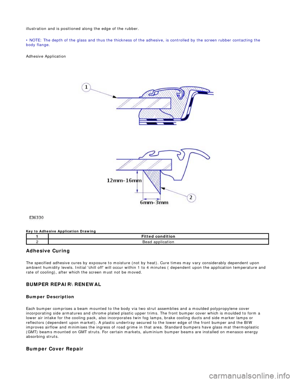
illustration and is positioned along the edge of the rubber.
• NOTE: The depth of the glass and thus the thickness of the ad hesive, is controlled by the screen rubber contacting the
body flange.
Adhesive Application
Key to Adhesive Application Drawing
Adhesive Curing
The specified adhesive cures by exposure to moisture (not by heat). Cure times may vary considerably dependent upon
ambient humidity levels. Initial 'chill off' will occur within 1 to 4 minutes ( dependent upon the application temperature and
rate of cooling), after which the screen must not be moved.
BUMPER REPAIR\RENEWAL
Bumper Description
Each bumper comprises a beam mounte d to the body via two strut assemblies and a moulded polypropylene cover
incorporating side armatures and chrome plated plastic upper trims. The front bumper cover which is moulded to form a
lower air intake for the cooling pack, also incorporates twin fog lamps, brake cooling ducts and side marker lamps or
reflectors (dependent upon market). A plastic undertray secured to the lower edge of the front bumper and the BIW
improves airflow and minimises the ingres s of road grime in that area. Standard bumpers have glass mat thermoplastic
(GMT) beams mounted on GMT struts. For certain markets, aluminium bumper beams are installed on menasco energy
absorbing struts.
Bumper Cover Repair
1Fitted condition
2Bead application