air control JAGUAR X308 1998 2.G Service Manual
[x] Cancel search | Manufacturer: JAGUAR, Model Year: 1998, Model line: X308, Model: JAGUAR X308 1998 2.GPages: 2490, PDF Size: 69.81 MB
Page 925 of 2490
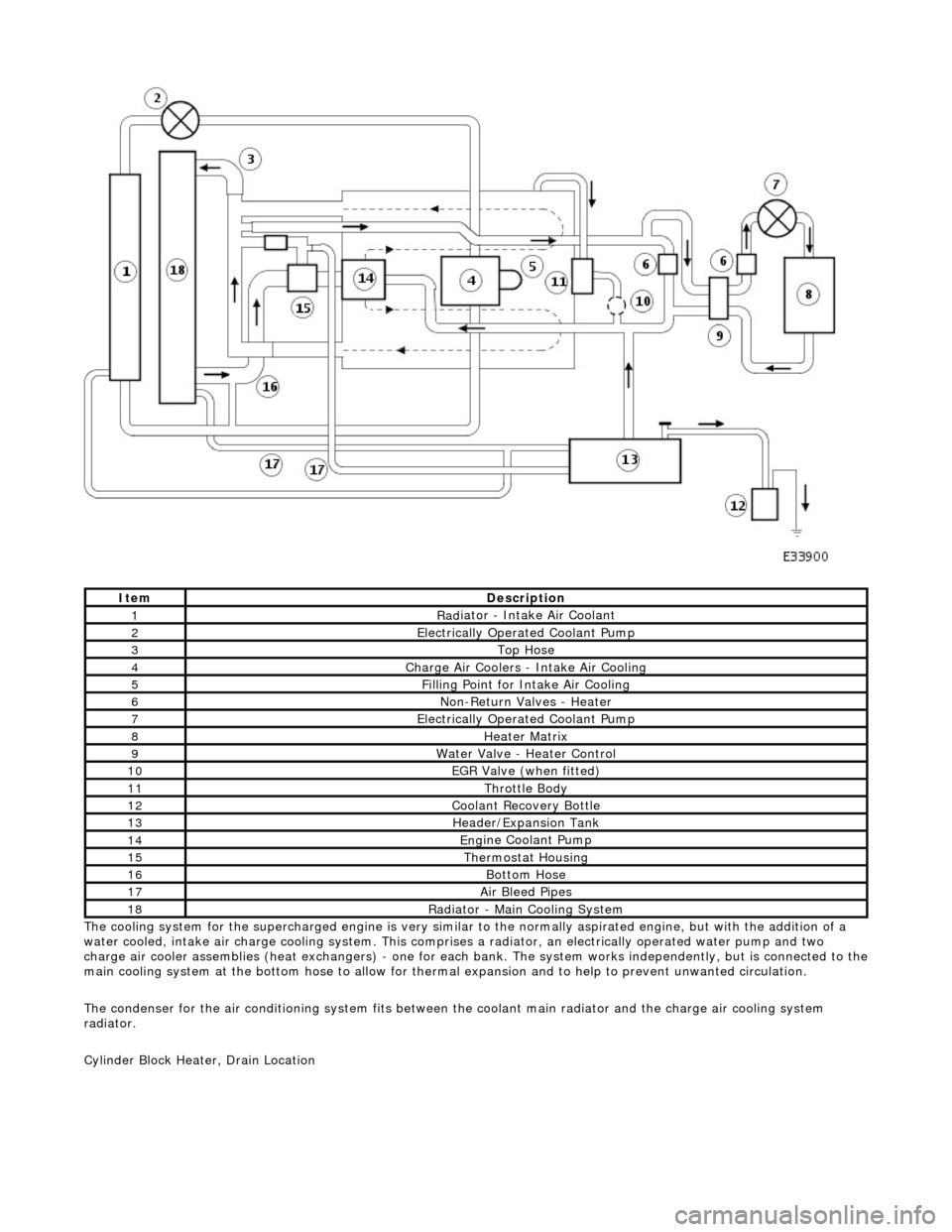
T
he cooling system for the supercharged engine is very similar
to the normally aspirated engine, but with the addition of a
water cooled, intake air charge cooling system. This comprises a radiator, an electrically operated water pump and two
charge air cooler assemblies (heat exchangers) - one for each bank. The system works independently, but is connected to the
main cooling system at the bottom hose to allow for therma l expansion and to help to prevent unwanted circulation.
The condenser for the air conditioning system fits between th e coolant main radiator and the charge air cooling system
radiator.
Cylinder Block Heater, Drain Location
ItemDe
scription
1Rad
iator - Intake Air Coolant
2Ele
ctrically Operated Coolant Pump
3Top Hose
4Charge Air Coo
lers -
Intake Air Cooling
5Fi
lling Point for Intake Air Cooling
6N
on-Return Valves - Heater
7Ele
ctrically Operated Coolant Pump
8Hea
ter Matrix
9Wate
r Valve - Heater Control
10EGR V
alve (when fitted)
11Thr
ottle Body
12Coolan
t Recovery Bottle
13H
eader/Expansion Tank
14Eng
ine Coolant Pump
15The
rmostat Housing
16Bottom
Hose
17Air Bleed
Pipes
18Rad
iator - Main Cooling System
Page 926 of 2490
A coola n
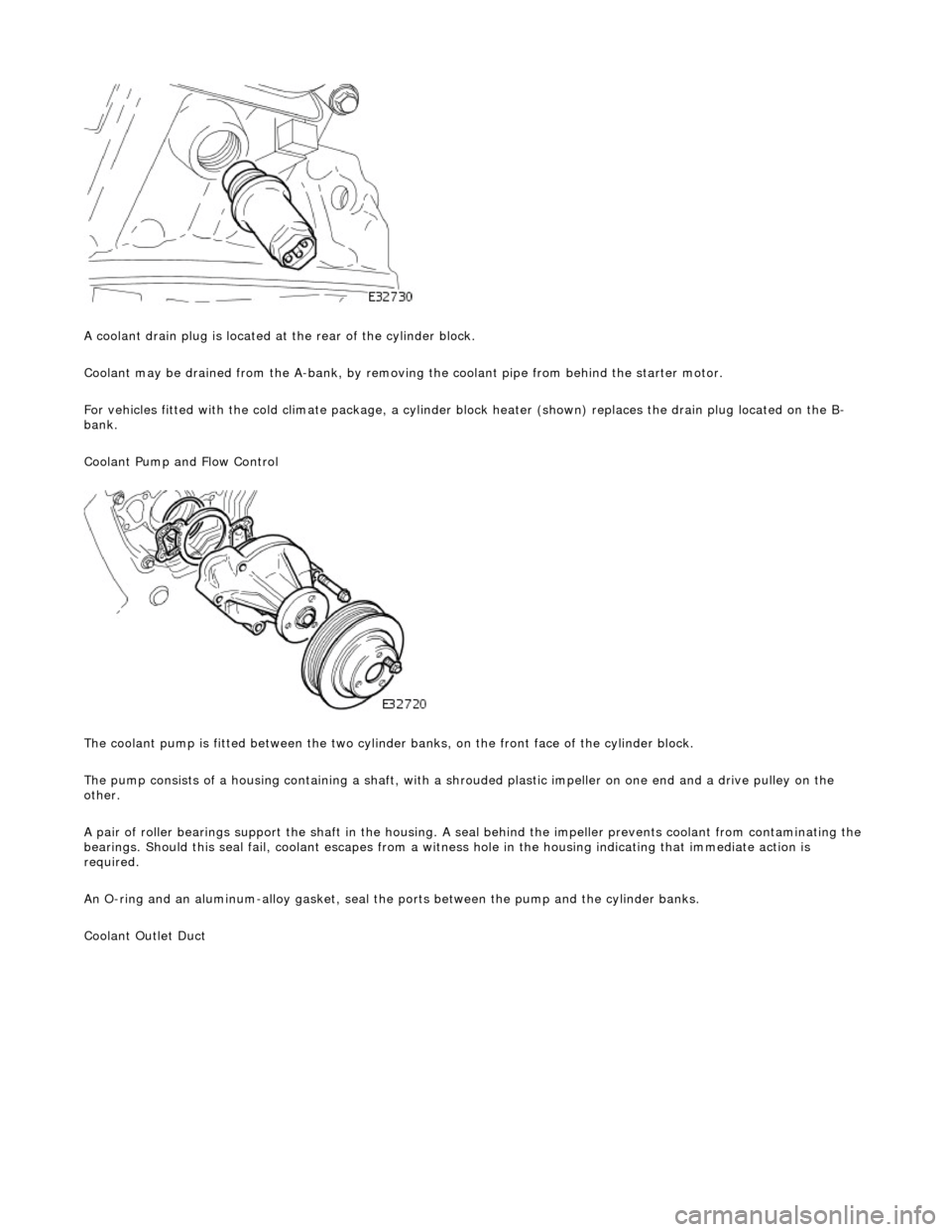
t drain plug is located at the rear of the cylinder block.
Coolant may be drained from the A-bank, by removing the coolant pipe from behind the starter motor.
For vehicles fitted with the cold climate package, a cylinder block heater (shown) replaces the drain plug located on the B-
bank.
Coolant Pump and Flow Control
The coolant pump is fitted between the two cylinder banks, on the front face of the cylinder block.
The pump consists of a housing containing a shaft, with a sh rouded plastic impeller on one end and a drive pulley on the
other.
A pair of roller bearings support the shaft in the housing. A seal behind the impeller prevents coolant from contaminating the
bearings. Should this seal fail, coolant escapes from a witness hole in the housin g indicating that immediate action is
required.
An O-ring and an aluminum-alloy gasket, seal the ports between the pump and the cylinder banks.
Coolant Outlet Duct
Page 928 of 2490
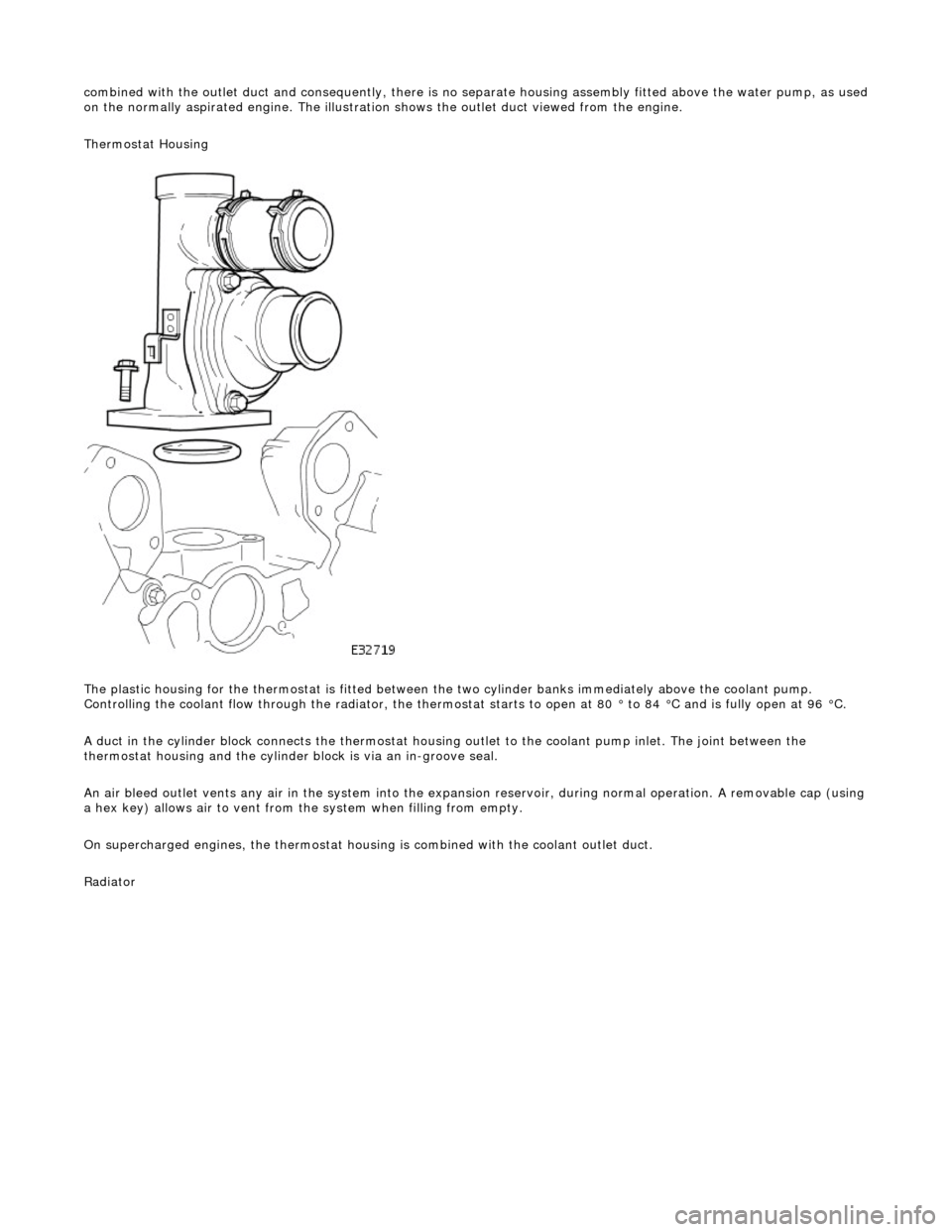
combin
ed with the outlet duct and consequently, there is no separate housin
g assembly fitted above the water pump, as used
on the normally aspirated engine. The illustration shows the outlet duct viewed from the engine.
Thermostat Housing
The plastic housing for the thermostat is fitted between th e two cylinder banks immediately above the coolant pump.
Controlling the coolant flow through the radiator, the thermostat starts to open at 80 ° to 84 °C and is fully open at 96 °C.
A duct in the cylinder block connects the thermostat housing outlet to the coolant pump inlet. The joint between the
thermostat housing and the cylinder block is via an in-groove seal.
An air bleed outlet vents an y air in the system into the expansion reservoir, durin
g normal operation. A removable cap (usin g
a hex key) allows air to vent from the system when filling from empty.
On supercharged engines, the thermostat housin g is combined with the coolant outlet duct.
Radiator
Page 930 of 2490
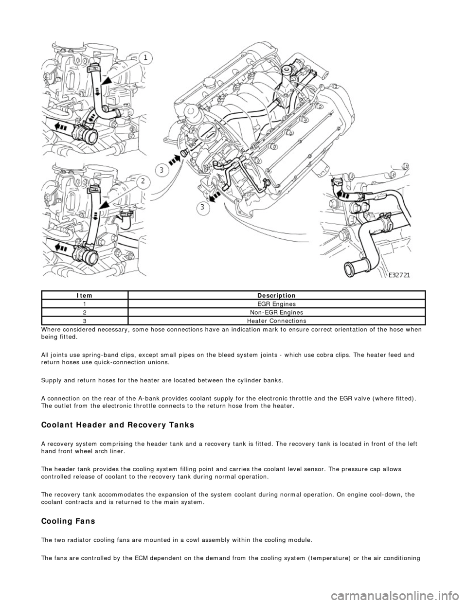
Whe r
e considered necessary, some hose conn
ections have an indication mark to ensure correct orientation of the hose when
being fitted.
All joints use spring-band clips, except small pipes on the bleed system joints - which use cobra clips. The heater feed and
return hoses use quick-connection unions.
Supply and return hoses for the heater are located between the cylinder banks.
A connection on the rear of the A-bank provides coolant supply for the electronic throttle and the EGR valve (where fitted).
The outlet from the electronic throttle connects to the return hose from the heater.
Cool
ant Header and Recovery Tanks
A recovery system comp
rising the header tank
and a recovery tank is fitted. The recove ry tank is located in front of the left
hand front wheel arch liner.
The header tank provides the cooling system filling point and carries the coolant level sensor. The pressure cap allows
controlled release of coolant to the re covery tank during normal operation.
The recovery tank accommodates the expansion of the system coolant during normal operation. On engine cool-down, the
coolant contracts and is returned to the main system.
Coo lin
g Fans
The two
rad
iator cooling fans are mounted in
a cowl assembly within the cooling module.
The fans are controlled by the ECM dependent on the demand fr om the cooling system (temperature) or the air conditioning
ItemDescrip
tion
1EGR
E
ngines
2Non
-
EGR Engines
3Hea
ter Connections
Page 956 of 2490
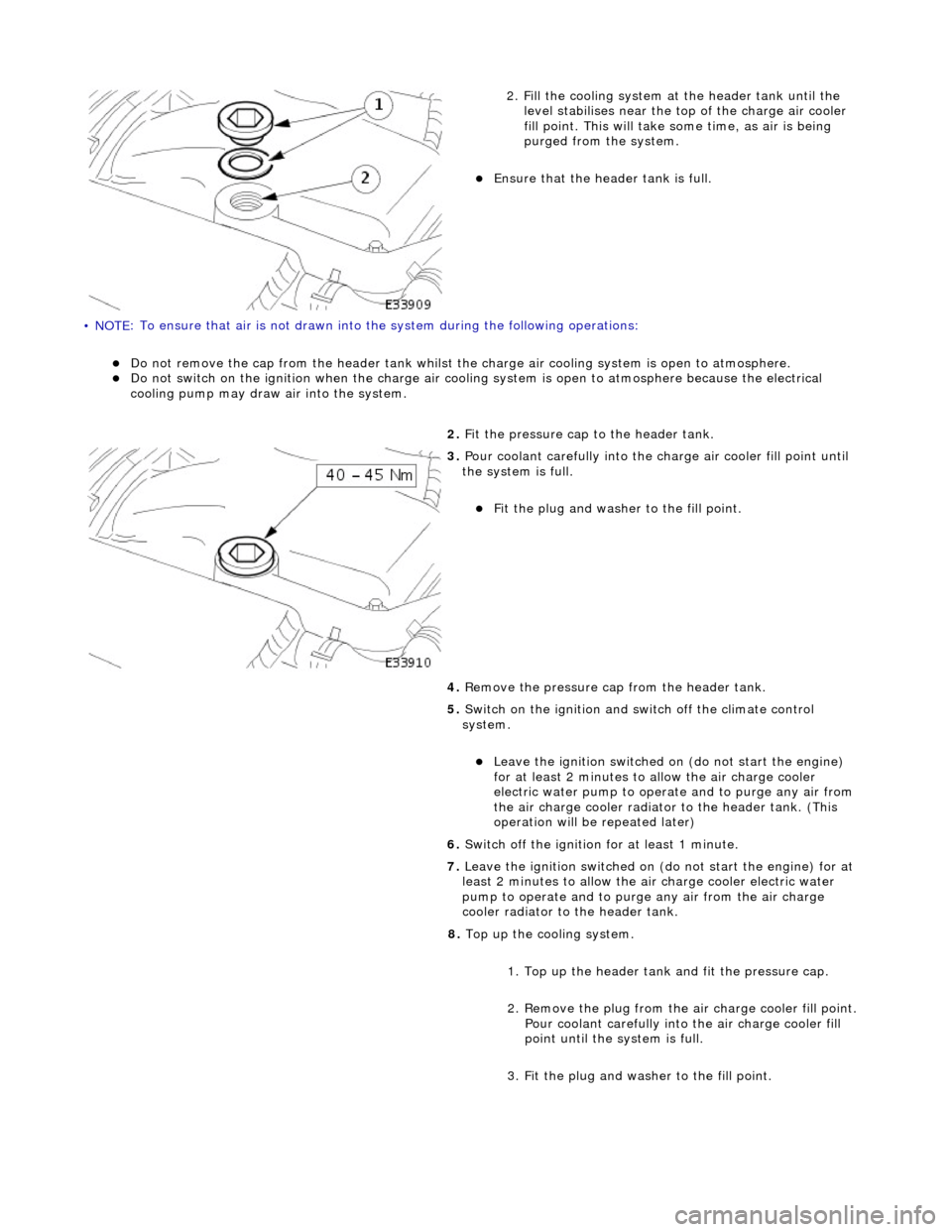
• NOTE
: To ensure that
air is not drawn into the system during the following operations:
Do
not remove the cap from the header tank whilst the
charge air cooling system is open to atmosphere.
Do
not switch on the ignition when th
e charge air cooling system is open to atmosphere because the electrical
cooling pump may draw air into the system.
2. Fi
ll the cooling system at the header tank until the
level stabilises near the to p of the charge air cooler
fill point. This will take some time, as air is being
purged from the system.
Ensure that the head
er tank is full.
2. Fit the pressure cap to the header tank.
3. Pour coolant careful l
y into the charge air cooler fill point until
the system is full.
Fi t t
he plug and washer to the fill point.
4. Remove the pressure cap from the header tank.
5. Switch on the ignition and switch off the climate control
system.
Le ave
the ignition switched on (do not start the engine)
for at least 2 minutes to allow the air charge cooler
electric water pump to oper ate and to purge any air from
the air charge cooler radiator to the header tank. (This
operation will be repeated later)
6. Switch off the ignition for at least 1 minute.
7. Leave the ignition switched on (do not start the engine) for at
least 2 minutes to allow the air charge cooler electric water
pump to operate and to purg e any air from the air charge
cooler radiator to the header tank.
8. Top up the cooling system.
1. Top up the header tank and fit the pressure cap.
2. Remove the plug from the air charge cooler fill point. Pour coolant carefully into the air charge cooler fill
point until the system is full.
3. Fit the plug and washer to the fill point.
Page 957 of 2490
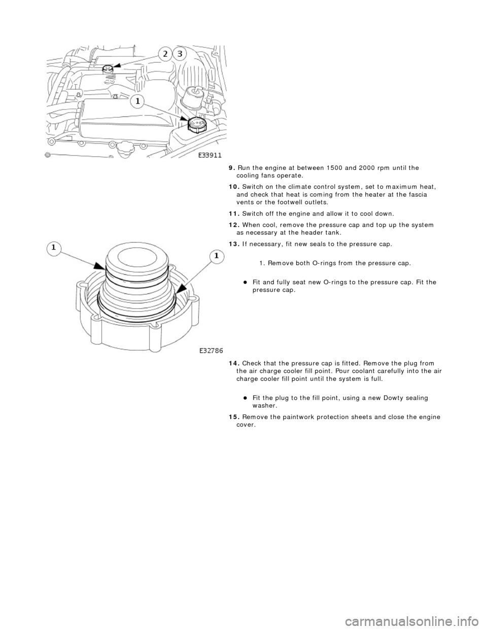
9.
R
un the engine at between 1500 and 2000 rpm until the
cooling fans operate.
10. Switch on the climate control system, set to maximum heat,
and check that heat is coming from the heater at the fascia
vents or the footwell outlets.
11. Switch off the engine and allow it to cool down.
12. When cool, remove the pressure cap and top up the system
as necessary at the header tank.
13
.
If necessary, fit new seals to the pressure cap.
1. Remove both O-rings from the pressure cap.
Fit and
fully seat new O-rings
to the pressure cap. Fit the
pressure cap.
14. Check that the pressure cap is fitted. Remove the plug from
the air charge cooler fill point. Pour coolant carefully into the air
charge cooler fill point until the system is full.
F
it the plug to the fill poin
t, using a new Dowty sealing
washer.
15. Remove the paintwork protection sheets and close the engine
cover.
Page 1013 of 2490
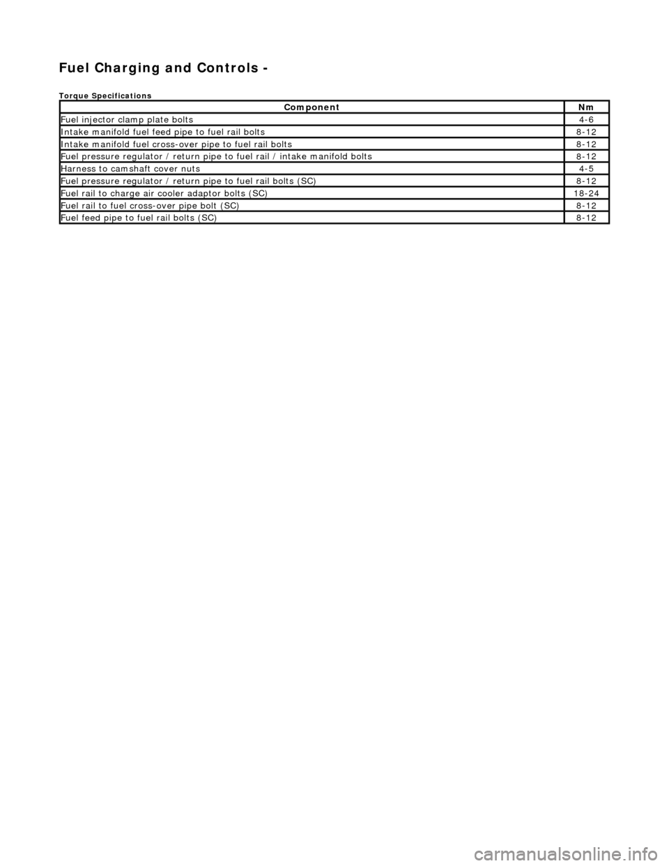
Fuel Ch
arging and Controls -
Torque Specific
ations
Com
ponent
Nm
Fue
l injector cl
amp plate bolts
4-
6
Inta
ke manifold fuel feed pipe to fuel rail bolts
8-
12
Inta
ke manifold fuel cross-over pipe to fuel rail bolts
8-
12
F
uel pressure regulator /
return pipe to fuel rail / intake manifold bolts
8-
12
Harness to
camshaft cover nuts
4-
5
F
uel pressure regulator / return
pipe to fuel rail bolts (SC)
8-
12
F
uel rail to charge air cooler adaptor bolts (SC)
18
-24
F
uel rail to fuel cross-over pipe bolt (SC)
8-
12
F
uel feed pipe to fuel rail bolts (SC)
8-
12
Page 1015 of 2490
Fuel D
istribution
Fuel is supplied to th
e engine
via eight fuel injectors (one pe r cylinder). The injectors are located in two fuel rails which r un
the length of each cylinder bank and ar e integral with the air intake manifold.
Fuel pumped from the tank enters a feed pipe at the rear of bank 2. Fuel flow is along bank 2 fuel rail, across the top front
of the engine (cross-over pipe) and through bank 1 fuel rail, the unused fuel re turning to the tank via a pressure regulator.
The fuel injectors are each controlled electrically from the engine control module (ECM).
A test valve is fitted to the cross-over pipe connecting the fu el rails at the front of the intake manifold. This valve allows the
fuel system to be depr essurized during servicin g and troubleshooting.
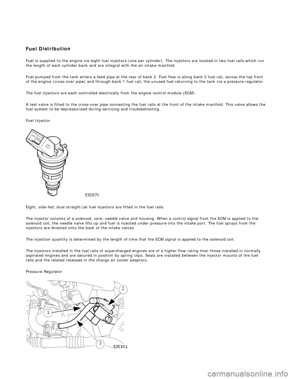
Fuel Injector
Eight, side-fed, dual straight-jet fuel injectors are fi tted in the fuel rails.
The injector consists of a solenoid, core, needle valve and ho using. When a control signal from the ECM is applied to the
solenoid coil, the needle valve lifts up and fuel is injected under pressure into the intake port. The fuel sprays from the
injectors are directed onto the back of the intake valves.
The injection quantity is determined by the length of time that the ECM signal is applied to the solenoid coil.
The injectors installed in the fuel rails of supercharged engines are of a higher flow rating than those installed in normally
aspirated engines and are secured in position by spring clips. Seals are instal led between the injector mounts of the fuel
rails and the related re cesses in the charge air cooler adaptors.
Pressure Regulator
Page 1020 of 2490
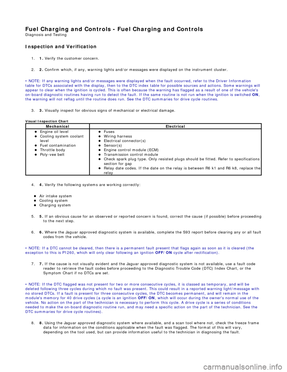
Fuel Char
ging and Controls - Fuel Charging and Controls
D
iagn
osis and Testing
I
n
spection and Verification
1.
1. Veri fy the customer concern.
2. 2. Confi
rm which, if any, warning li
ghts and/or messages were displayed on the instrument cluster.
• NOTE: If any warning lights and/or me ssages were displayed when the fault occurred, refer to the Driver Information
table for DTCs associated with the display, then to the DTC index table for possible sources and actions. Some warnings will
appear to clear when the ignition is cycl ed. This is often because the warning has flagged as a resu lt of one of the vehicle's
on-board diagnostic routines having run to detect the fault. If the same routine is not run when the ignition is switched ON,
the warning will not reflag until the routine does run. See the DTC summaries for drive cycle routines.
3. 3. Visually inspect for obvious signs of mechanical or electrical damage.
Vi
sual Inspection Chart
4.
4. Veri fy the foll
owing syst
ems are working correctly:
Air intake
system
Cooling system
Charging system
5. 5. If
an obvious cause for an observed or
reported concern is found, correct th e cause (if possible) before proceeding
to the next step.
6. 6. Where the Jaguar approved diagnostic sy stem is available, complete the S93 report before clearing any or all fault
codes from the vehicle.
• NOTE: If a DTC cannot be cleared, then there is a permanent fault present that flag s again as soon as it is cleared (the
exception to this is P1260, which will only clear following an ignition OFF/ON cycle after rectification).
7. 7. If the cause is not visually evident and the Jaguar approv ed diagnostic system is not available, use a fault code
reader to retrieve the fault codes be fore proceeding to the Diagnostic Trou ble Code (DTC) Index Chart, or the
Symptom Chart if no DTCs are set.
• NOTE: If the DTC flagged was not present for two or more co nsecutive cycles, it is classed as temporary, and will be
deleted following three cycl es during which no fault was present. This could result in a reported wa rning light/message with
no stored DTCs. If a fault is present for three consecutive cycles, the DTC becomes permanent, and will remain in the
module's memory for 40 drive cycl es (a cycle is an ignition OFF/ON, which will occur during the owner's normal use of the
vehicle. No action on the part of the technician is necessary to perform this cycle. A drive cycle is a series of conditions
needed to make the on-board diagnostic ro utine run, and may need a specific action on the part of the technician. See the
DTC summaries for drive cycle routines).
8. 8. Using the Jaguar approved diagnostic system where available, and a scan tool where not, check the freeze frame
data for information on the conditions applicable when the fault was flagged. The format of this will vary,
depending on the tool used, but can pr ovide information useful to the technician in diagnosing the fault.
MechanicalElectrical
Engine
oil level
Coo
ling system coolant
lev
el
Fuel contamination
Throttle body Poly-ve
e belt
Fu
ses
W
i
ring harness
E
l
ectrical connector(s)
Sens
o
r(s)
Engine
control module (E
CM)
Tran
s
mission control module
Check spark plu
g type. Only r
e
sisted plugs should be fitted. Refer to specifications
section for gap
Relay date codes. I
f the date on the rela
y is between R6 k1 and R6 k8, replace the
relay
Page 1022 of 2490
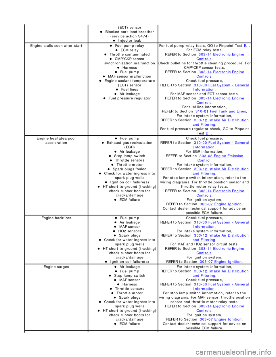
(ECT) se
nsor
Blocked part-load breather
(s
ervice action S474)
Injec
t
or leak
Engine stalls
soon
after start
F
u
el pump relay
ECM relay Thr
o
ttle contaminated
CMP/CKP sen
s
or
synchronization malfunction
Harness Fuel
pump
MAF
s
ensor malfunction
Engine coolan
t
temperature
(ECT) sensor
Fue l
lines
Air leakage Fu
el pressure regulator
F
o
r fuel pump relay tests,
GO to Pinpoint Test E.
.
F or ECM
relay tests,
REFER to Section 303
-14 Elec tronic En
gine
Controls.
Check bull etins for throttl
e cleaning procedure. For
CMP/CKP sensor tests,
REFER to Section 303
-14 Elec tronic En
gine
Controls.
Chec k fu
el pressure,
REFER to Section 310
-00 Fu
el System
- Ge
n
eral
Informati
o
n
.
F or MAF sensor and
ECT sensor tests,
REFER to Section 303
-14 Electronic En
gine
Controls.
For fuel l
ine information,
REFER to Section 310
-01
Fuel Tank and Lines
.
F or i
ntake system information,
REFER to Section 303
-1 2
Intake Air Distribution
and F
ilt
ering
.
F o
r fuel pressure regulato
r check, GO to Pinpoint
Test D.
.
Engine h e
sitates/poor
acceleration
Fue l
pump
Exhaus
t gas
recirculation
(EGR)
Air leakage Stop lamp swi t
ch
Throttl
e
sensors
Throttl
e
motor
Spark plugs
fouled
Check f
o
r water ingress into
spark plug wells
Ignition coil fail
ure(s)
HT sho
rt to ground (tracking)
check rubber
boots for
cracks/damage
ECM failu r
e
Chec
k fu
el pressure,
REFER to Section 310
-00 Fu
el System
- Ge
n
eral
Informati
o
n
.
F o
r EGR information,
REFER to Section 303
-08 En gin
e Emission
Control.
F or i
ntake system information,
REFER to Section 303
-1 2
Intake Air Distribution
and F
ilt
ering
.
F or stop l
amp switch in
formation, refer to the
wiring diagrams. For throttle position sensor and throttle motor relay tests,
REFER to Section 303
-14 Elec tronic En
gine
Controls.
For ign i
tion system,
REFER to Section 303
-07 En
gine Ignition
.
Contact dealer techn i
cal
support for advice on
possible ECM failure.
Engine ba ckfiresFuel
pump
Air leakage MAF s
e
nsor
HO2 sensors Spark plugs
Check fo
r water ingress into
spark plug wells
HT short to ground (tracking) check rubber
boots for
cracks/damage
Ignition coil fail
ure(s)
Chec
k fu
el pressure,
REFER to Section 310
-00 Fu
el System
- Ge
n
eral
Informati
o
n
.
F or i
ntake system information,
REFER to Section 303
-1 2
Intake Air Distribution
and F
ilt
ering
.
For MAF and HO2
sensor circuit tests,
REFER to Section 303
-14 Electronic En
gine
Controls.
For igni
tion system,
REFER to Section 303
-07 En
gine Ignition
.
Engine
s
urges
Air leakage Fue
l
pump
Stop lamp swi
t
ch
MAF s
e
nsor
Harness Throttl
e
sensors
Throttl
e
motor
Spark plugs
Check fo
r water ingress into
spark plug wells
HT sho rt to ground (tracking)
check rubber
boots for
cracks/damage
ECM failu r
e
F
or i
ntake system information,
REFER to Section 303
-1 2
Intake Air Distribution
and F
ilt
ering
.
Chec k fu
el pressure,
REFER to Section 310
-00 Fu
el System
- Gen
e
ral
Informati
o
n
.
F or stop l
amp switch in
formation, refer to the
wiring diagrams. For MAF se nsor, throttle position
sensor and throttle motor relay tests,
REFER to Section 303
-14 Elec tronic En
gine
Controls.
For ign i
tion system,
REFER to Section 303
-07 En
gine Ignition
.
Contact dealer techn i
cal
support for advice on
possible ECM failure.