drain bolt JAGUAR X308 1998 2.G User Guide
[x] Cancel search | Manufacturer: JAGUAR, Model Year: 1998, Model line: X308, Model: JAGUAR X308 1998 2.GPages: 2490, PDF Size: 69.81 MB
Page 705 of 2490
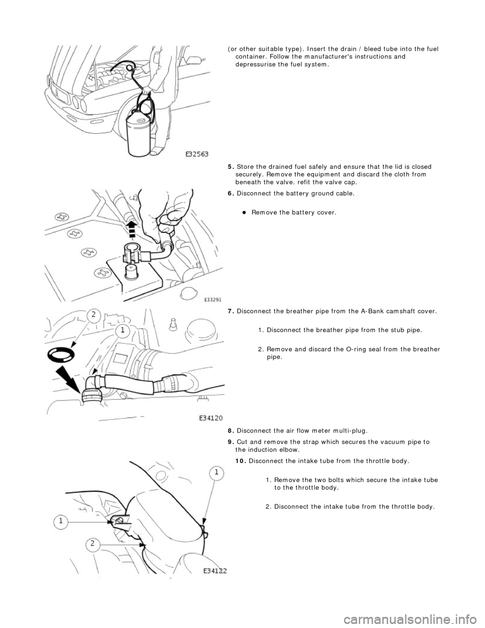
(or other sui
table type). Insert the drain / bleed tube
into the fuel
container. Follow the manufa cturer's instructions and
depressurise the fuel system.
5. Store the drained fuel safely and ensure that the lid is closed
securely. Remove the equipmen t and discard the cloth from
beneath the valve. refit the valve cap.
6. Di
sconnect the batt
ery ground cable.
R
emove the battery cover.
7. Disconnect the breather pipe fro m the
A-Bank camshaft cover.
1. Disconnect the breather pipe from the stub pipe.
2. Remove and discard the O-ring seal from the breather
pipe.
8. Disconnect the air fl ow meter multi-plug.
9. Cut and remove the strap which secures the vacuum pipe to
the induction elbow.
10
.
Disconnect the intake tube from the throttle body.
1. Remove the two bolts which secure the intake tube to the throttle body.
2. Disconnect the intake tube from the throttle body.
Page 719 of 2490
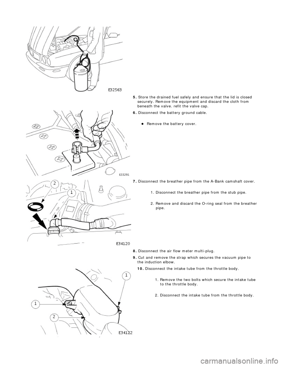
5. Store the drained fuel safely and ensure that the lid is closed
securely. Remove the equipmen t and discard the cloth from
beneath the valve. refit the valve cap.
6. Disconnect the batt ery ground cable.
Remove the battery cover.
7. Disconnect the breather pipe fro m the A-Bank camshaft cover.
1. Disconnect the breather pipe from the stub pipe.
2. Remove and discard the O-ring seal from the breather
pipe.
8. Disconnect the air fl ow meter multi-plug.
9. Cut and remove the strap which secures the vacuum pipe to
the induction elbow.
10. Disconnect the intake tube from the throttle body.
1. Remove the two bolts which secure the intake tube to the throttle body.
2. Disconnect the intake tube from the throttle body.
Page 750 of 2490

Engine - Oil Pan
In-vehicle Repair
Removal
Installation
1. Open the engine compartment and fit paintwork protection
sheets.
2. Raise the vehicle on a ramp.
3. Drain the engine oil.
1. Position the waste oil bowser.
2. Remove the oil pan drain plug and drain the engine
oil.
Wipe the drain plug and refit it, to prevent oil dripping.
Move the oil bowser away from the vehicle.
4. Remove the oil pan.
1. Remove the eighteen bolt s which secure the oil pan
to the oil pan body.
2. Remove the oil pan from the oil pan body.
3. Remove the gasket from the oil pan body assembly.
5. Clean and inspect the sealing faces on the oil pan body
assembly.
Clean and inspect the new oil pan mating face.
1. Fit the oil pan gasket to the oil pan body assembly.
Insert the seal into the locating positions in the groove,
working around from a corner.
Press in the remainder of th e seal, following the same
procedure.
2. Fit the oil pan to the oil pan body.
1. Position and align the oil pan.
2. Fit, but do not tighten, all eighteen bolts which secure
the oil pan.
Page 751 of 2490
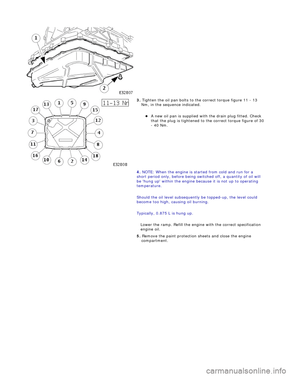
3. Tighten the oil pan bolts to the correct torque figure 11 - 13
Nm, in the sequence indicated.
A new oil pan is supplied with the drain plug fitted. Check
that the plug is tightened to the correct torque figure of 30 - 40 Nm.
4. NOTE: When the engine is star ted from cold and run for a
short period only, before being swit ched off, a quantity of oil will
be 'hung up' within the engine because it is not up to operating
temperature.
Should the oil level subsequently be topped-up, the level could
become too high, causing oil burning.
Typically, 0.875 L is hung up.
Lower the ramp. Refill the engine with the correct specification
engine oil.
5. Remove the paint protection sheets and close the engine
compartment.
Page 752 of 2490

Engine - Oil Pan Gasket
In-vehicle Repair
Removal
Installation
1. Open the engine compartment and fit paintwork protection
sheets.
2. Raise the vehicle on a ramp.
3. Drain the engine oil.
1. Position the waste oil bowser.
2. Remove the drain plug and drain the engine oil.
Fit a new sealing washer to the drain plug.
Wipe the drain plug and refit it to the oil pan to prevent oil
dripping.
Move the oil bowser away from the vehicle.
4. Remove the oil pan.
1. Remove the eighteen bolt s which secure the oil pan.
2. Remove the oil pan.
3. Remove the gasket.
5. Clean and inspect the sealing face s on the oil pan. and mating
faces.
1. Fit the oil pan gasket to the cylinder block adaptor body.
Insert the seal into the locating positions in the groove,
working around from a corner.
Press in the remainder of th e seal, following the same
procedure.
2. Fit the oil pan.
1. Position and align the oil pan.
2. Fit, but do not tighten, all eighteen bolts which secure
the oil pan.
Page 753 of 2490
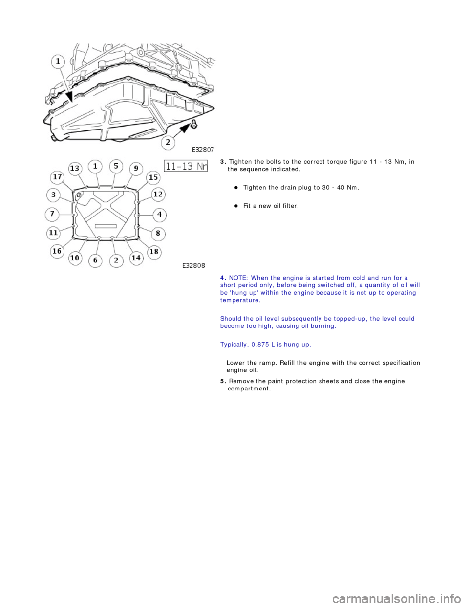
3. Tighten the bolts to the correct torque figure 11 - 13 Nm, in
the sequence indicated.
Tighten the drain plug to 30 - 40 Nm.
Fit a new oil filter.
4. NOTE: When the engine is star ted from cold and run for a
short period only, before being swit ched off, a quantity of oil will
be 'hung up' within the engine because it is not up to operating
temperature.
Should the oil level subsequently be topped-up, the level could
become too high, causing oil burning.
Typically, 0.875 L is hung up.
Lower the ramp. Refill the engine with the correct specification
engine oil.
5. Remove the paint protection sheets and close the engine
compartment.
Page 830 of 2490

Engine - Upper Oil Pan3.2L NA V8 - AJ26
In-vehicle Repair
Removal
Special Tool(s)
Installer/remover, Oil Filter
303-752
1. Disconnect the batt ery ground cable.
Remove the battery cover.
2. Open the engine compartment and fit paintwork protection
sheets.
3. Set the engine compartment cover to the service access
position.
4. Remove the timing cover and al l associated components, as
detailed in Operation 12.65.01.
5. Remove both front wheel and tyre assemblies. Refer to
Operation 74.20.05.
6. Remove the undertray. Re fer to Operation 76.22.90.
7. Remove the two bolts which secu re the generator cooling duct
to the oil pan body and remove the duct.
8. Remove the front cross member for access. Refer to Operation
76.10.05.
9. Drain the engine oil.
1. Position the waste oil bowser.
2. Remove the drain plug from the oil pan and drain the engine oil.
Fit a new sealing washer to the drain plug.
Page 831 of 2490
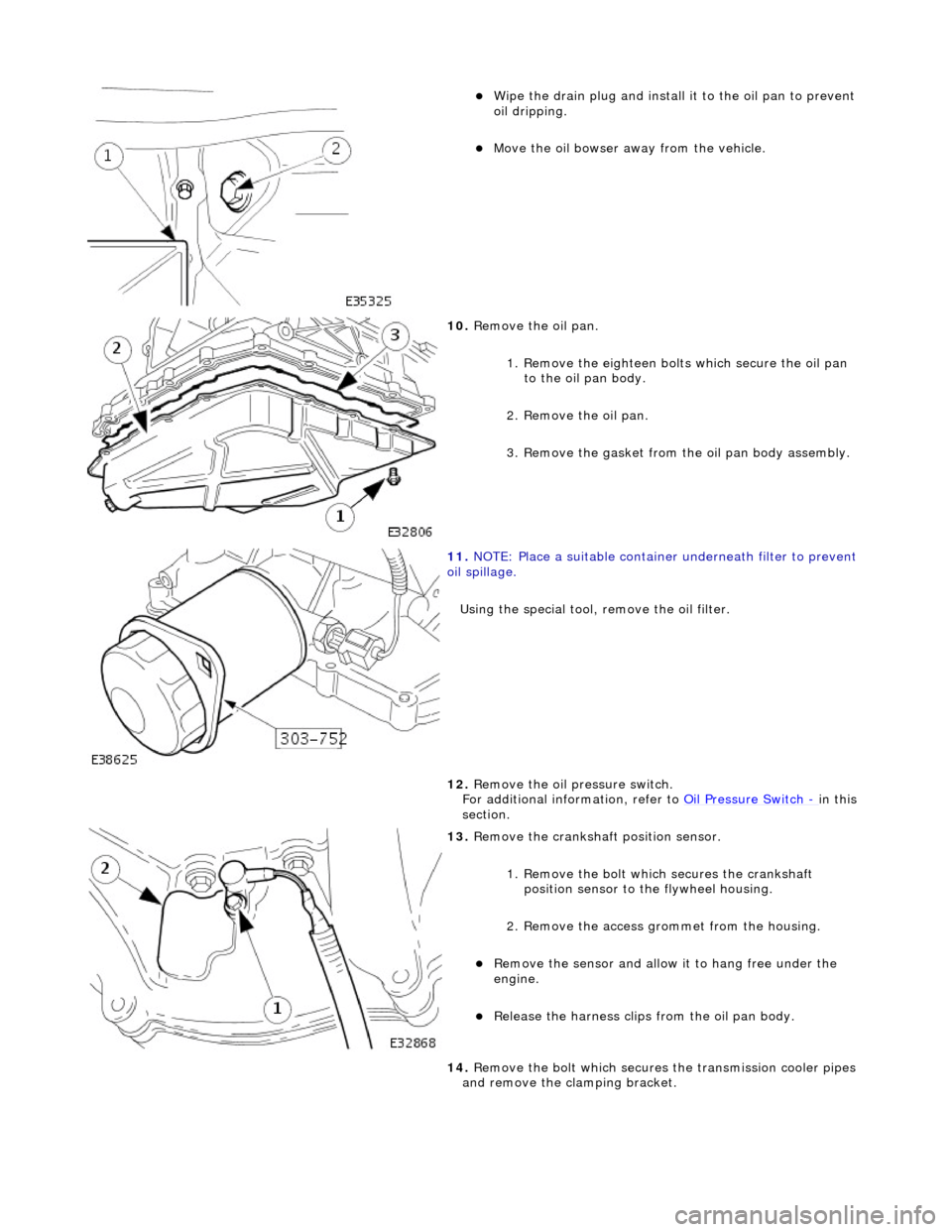
Wipe the drain plug and install it to the oil pan to prevent
oil dripping.
Move the oil bowser away from the vehicle.
10. Remove the oil pan.
1. Remove the eighteen bolt s which secure the oil pan
to the oil pan body.
2. Remove the oil pan.
3. Remove the gasket from the oil pan body assembly.
11. NOTE: Place a suitable container underneath filter to prevent
oil spillage.
Using the special tool, remove the oil filter.
12. Remove the oil pressure switch.
For additional information, refer to Oil Pressure Switch
- in this
section.
13. Remove the crankshaft position sensor.
1. Remove the bolt which secures the crankshaft position sensor to the flywheel housing.
2. Remove the access grommet from the housing.
Remove the sensor and allow it to hang free under the
engine.
Release the harness clips from the oil pan body.
14. Remove the bolt which secures the transmission cooler pipes
and remove the clamping bracket.
Page 836 of 2490

3. Install and tighten the bolts to 11-13 Nm.
7. Install the oil pan gasket to the oil pan body assembly.
Insert the seal into the locating positions in the groove,
working around from a corner.
Press in the remainder of th e seal, following the same
procedure.
8. Install the oil pan to the oil pan body.
1. Position and align the oil pan.
2. Install, but do not tighte n, all eighteen bolts which
secure the oil pan.
9. Tighten the bolts to the correct torque figure 11-13 Nm, in the
sequence indicated.
Tighten the drain plug to 30-40 Nm.
10. Install the oil pressure switch.
For additional information, refer to Oil Pressure Switch
- in this
section.
11. NOTE: Apply a suitable amount of clean engine oil to lubricate
the oil filter O-ring seal.
Using the special tool, install the oil filter.
Page 839 of 2490

Engine - Upper Oil Pan4.0L NA V8 - AJ27, 4.0L
In-vehicle Repair
Removal
Special Tool(s)
Installer/remover, Oil Filter
303-752
1. Disconnect the batt ery ground cable.
Remove the battery cover.
2. Open the engine compartment and fit paintwork protection
sheets.
3. Set the engine compartment cover to the service access
position.
4. Remove the timing cover and al l associated components, as
detailed in Operation 12.65.01.
5. Remove both front wheel and tyre assemblies. Refer to
Operation 74.20.05.
6. Remove the undertray. Re fer to Operation 76.22.90.
7. Remove the two bolts which secu re the generator cooling duct
to the oil pan body and remove the duct.
8. Remove the front cross member for access. Refer to Operation
76.10.05.
9. Drain the engine oil.
1. Position the waste oil bowser.
2. Remove the drain plug from the oil pan and drain the engine oil.
Fit a new sealing washer to the drain plug.