drain bolt JAGUAR X308 1998 2.G Owner's Manual
[x] Cancel search | Manufacturer: JAGUAR, Model Year: 1998, Model line: X308, Model: JAGUAR X308 1998 2.GPages: 2490, PDF Size: 69.81 MB
Page 840 of 2490

Wipe the drain plug and install it to the oil pan to prevent
oil dripping.
Move the oil bowser away from the vehicle.
10. Remove the oil pan.
1. Remove the eighteen bolt s which secure the oil pan
to the oil pan body.
2. Remove the oil pan.
3. Remove the gasket from the oil pan body assembly.
11. NOTE: Place a suitable container underneath filter to prevent
oil spillage.
Using the special tool, remove the oil filter.
12. Remove the oil pressure switch.
For additional information, refer to Oil Pressure Switch
- in this
section.
13. Remove the crankshaft position sensor.
1. Remove the bolt which secures the crankshaft position sensor to the flywheel housing.
2. Remove the access grommet from the housing.
Remove the sensor and allow it to hang free under the
engine.
Release the harness clips from the oil pan body.
14. Remove the bolt which secures the transmission cooler pipes
and remove the clamping bracket.
Page 845 of 2490

3. Install and tighten the bolts to 11-13 Nm.
7. Install the oil pan gasket to the oil pan body assembly.
Insert the seal into the locating positions in the groove,
working around from a corner.
Press in the remainder of th e seal, following the same
procedure.
8. Install the oil pan to the oil pan body.
1. Position and align the oil pan.
2. Install, but do not tighte n, all eighteen bolts which
secure the oil pan.
9. Tighten the bolts to the correct torque figure 11-13 Nm, in the
sequence indicated.
Tighten the drain plug to 30-40 Nm.
10. Install the oil pressure switch.
For additional information, refer to Oil Pressure Switch
- in this
section.
11. NOTE: Apply a suitable amount of clean engine oil to lubricate
the oil filter O-ring seal.
Using the special tool, install the oil filter.
Page 849 of 2490
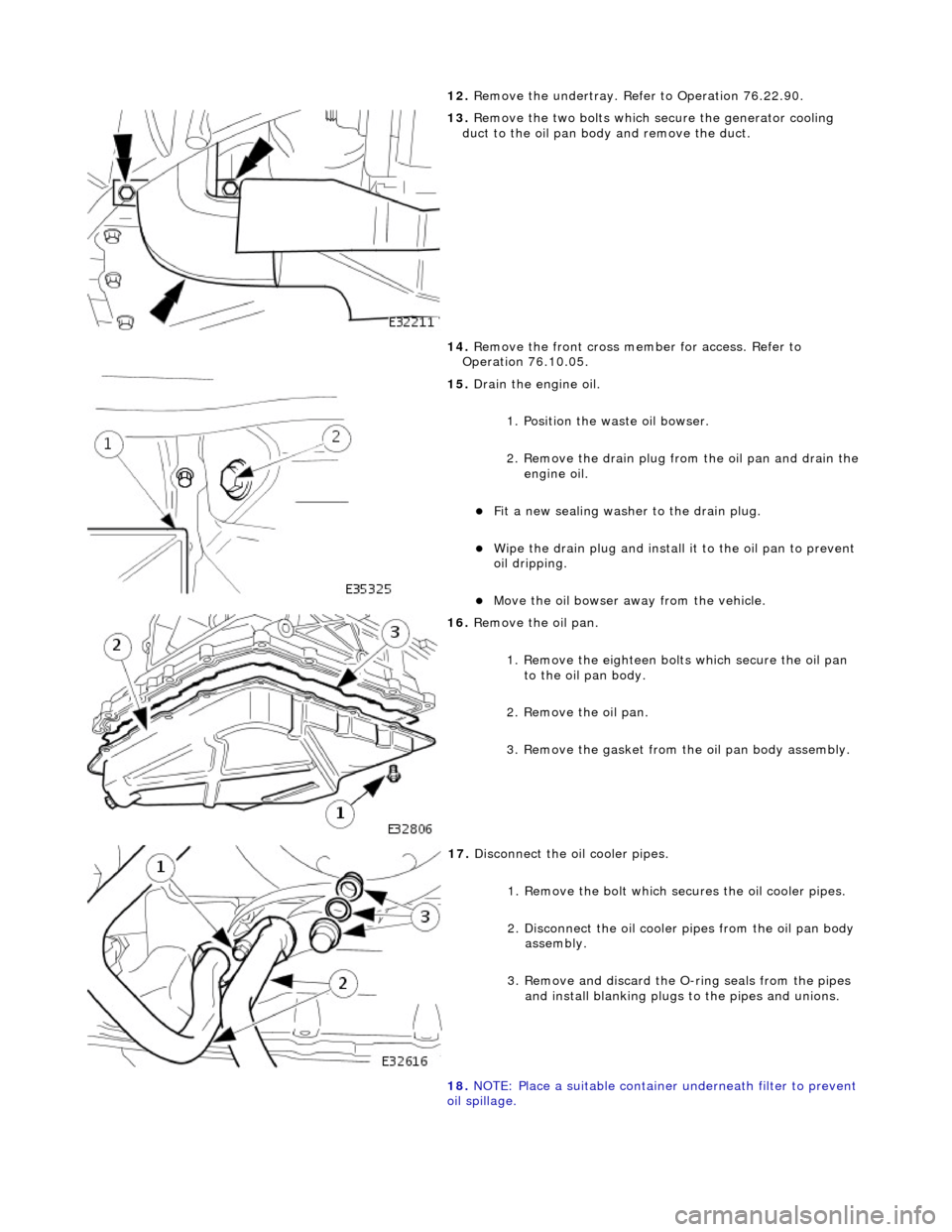
12. Remove the undertray. Re fer to Operation 76.22.90.
13. Remove the two bolts which se cure the generator cooling
duct to the oil pan body and remove the duct.
14. Remove the front cross member for access. Refer to
Operation 76.10.05.
15. Drain the engine oil.
1. Position the waste oil bowser.
2. Remove the drain plug from the oil pan and drain the engine oil.
Fit a new sealing washer to the drain plug.
Wipe the drain plug and install it to the oil pan to prevent
oil dripping.
Move the oil bowser away from the vehicle.
16. Remove the oil pan.
1. Remove the eighteen bolt s which secure the oil pan
to the oil pan body.
2. Remove the oil pan.
3. Remove the gasket from the oil pan body assembly.
17. Disconnect the oil cooler pipes.
1. Remove the bolt which secures the oil cooler pipes.
2. Disconnect the oil cooler pipes from the oil pan body
assembly.
3. Remove and discard the O-ring seals from the pipes
and install blanking plugs to the pipes and unions.
18. NOTE: Place a suitable container underneath filter to prevent
oil spillage.
Page 855 of 2490

3. Install and tighten the bolts to 11-13 Nm.
7. Install the oil pick-up pipe.
1. Install a new O-ring se al to the pick-up pipe.
2. Lubricate the O-ring seal with clean engine oil and install the pipe to the oil pan body.
3. Install and tighten the bolts to 11-13 Nm.
8. Install the oil pan gasket to the oil pan body assembly.
Insert the seal into the locating positions in the groove,
working around from a corner.
Press in the remainder of th e seal, following the same
procedure.
9. Install the oil pan to the oil pan body.
1. Position and align the oil pan.
2. Install, but do not tighte n, all eighteen bolts which
secure the oil pan.
10. Tighten the bolts to the correct torque figure 11-13 Nm, in
the sequence indicated.
Tighten the drain plug to 30-40 Nm.
Page 897 of 2490
• WARNINGS:
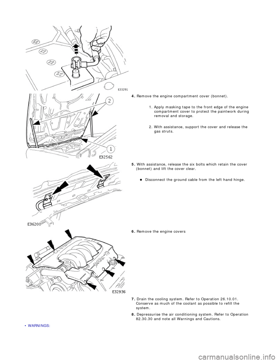
4. Remove the engine compartment cover (bonnet).
1. Apply masking tape to th e front edge of the engine
compartment cover to protect the paintwork during
removal and storage.
2. With assistance, support the cover and release the
gas struts.
5. With assistance, release the six bolts which retain the cover
(bonnet) and lift the cover clear.
Disconnect the ground cable from the left hand hinge.
6. Remove the engine covers
7. Drain the cooling system. Refer to Operation 26.10.01.
Conserve as much of the coolant as possible to refill the
system.
8. Depressurise the air conditioni ng system. Refer to Operation
82.30.30 and note all Wa rnings and Cautions.
Page 898 of 2490
ENSURE THAT ALL FIRE PREVENTION PROCEDURES ARE ACTIVE.
BEFORE PROCEEDING, IT IS ESSENTIAL THAT THE WARNING NOTES GIVEN IN SECTION 100-00 (UNDER THE
HEADING 'SAFETY PRECAUTIONS') ARE READ AND UNDERSTOOD.
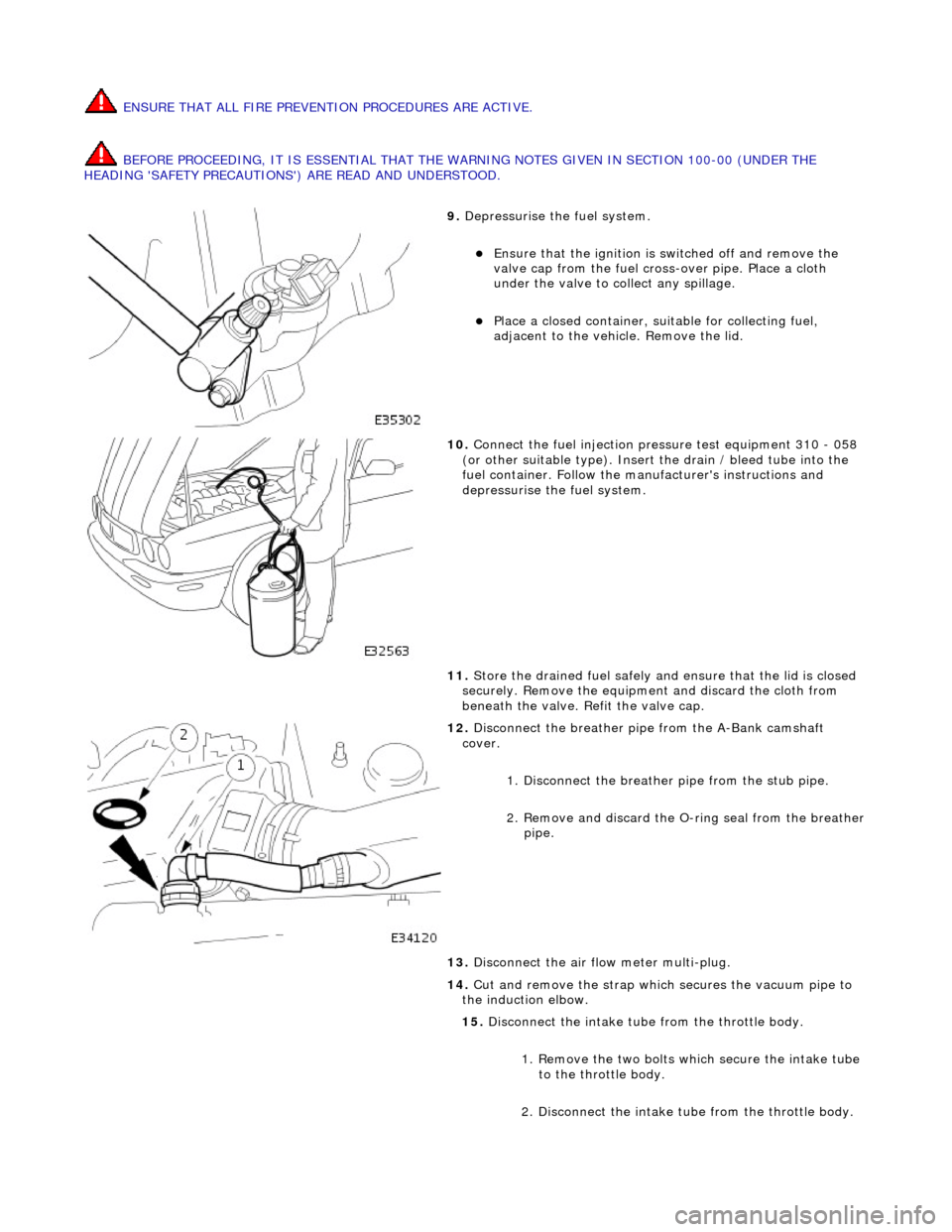
9. Depressurise the fuel system.
Ensure that the ignition is switched off and remove the
valve cap from the fuel cross-over pipe. Place a cloth
under the valve to collect any spillage.
Place a closed container, su itable for collecting fuel,
adjacent to the vehicle. Remove the lid.
10. Connect the fuel injection pressure test equipment 310 - 058
(or other suitable type). Insert the drain / bleed tube into the
fuel container. Follow the ma nufacturer's instructions and
depressurise the fuel system.
11. Store the drained fuel safely and ensure that the lid is closed
securely. Remove the equipmen t and discard the cloth from
beneath the valve. Refit the valve cap.
12. Disconnect the breather pipe from the A-Bank camshaft
cover.
1. Disconnect the breather pipe from the stub pipe.
2. Remove and discard the O-ring seal from the breather
pipe.
13. Disconnect the air flow meter multi-plug.
14. Cut and remove the strap which secures the vacuum pipe to
the induction elbow.
15. Disconnect the intake tube from the throttle body.
1. Remove the two bolts which secure the intake tube to the throttle body.
2. Disconnect the intake tube from the throttle body.
Page 901 of 2490
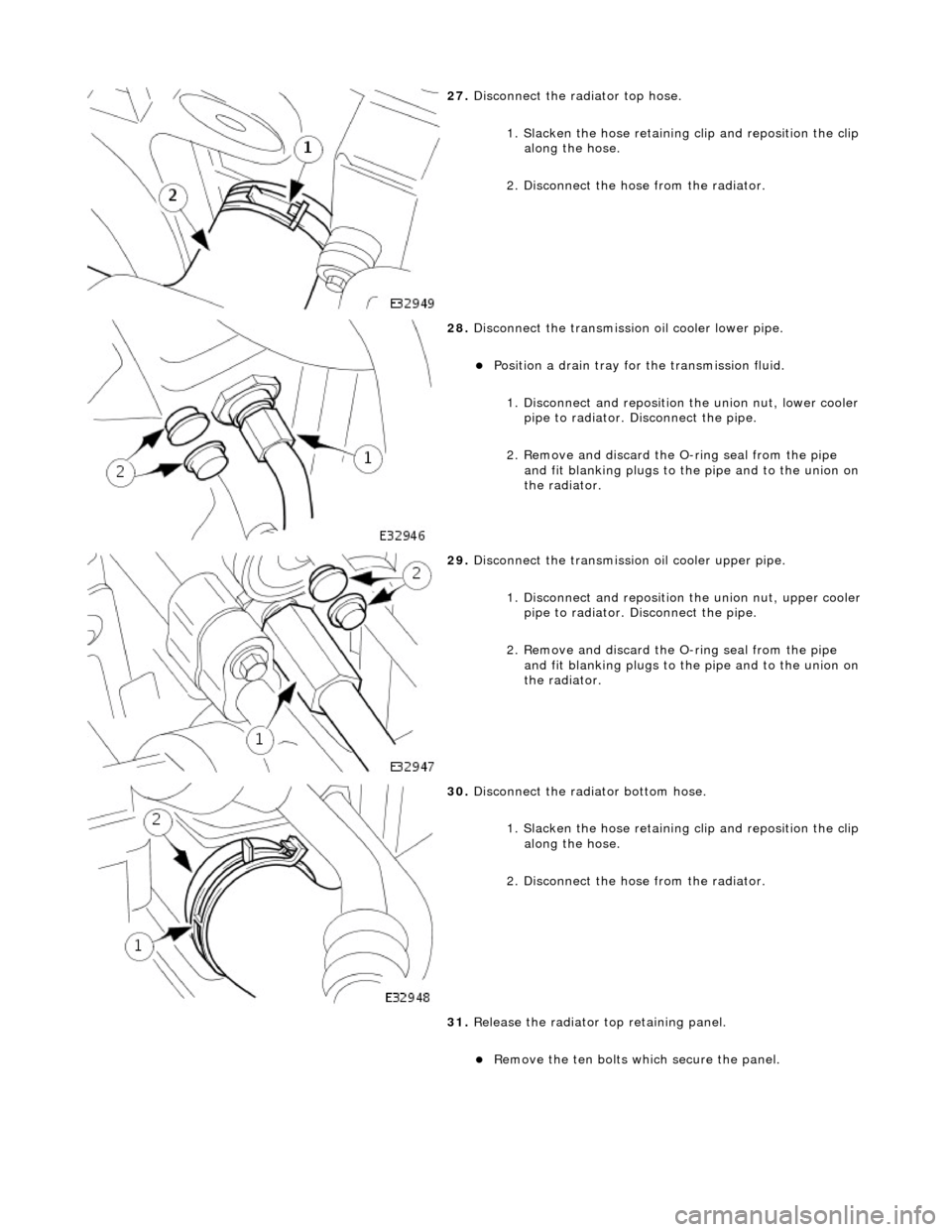
27. Disconnect the radiator top hose.
1. Slacken the hose retaining clip and reposition the clip
along the hose.
2. Disconnect the hose from the radiator.
28. Disconnect the transmission oil cooler lower pipe.
Position a drain tray for the transmission fluid.
1. Disconnect and reposition the union nut, lower cooler pipe to radiator. Di sconnect the pipe.
2. Remove and discard the O- ring seal from the pipe
and fit blanking plugs to the pipe and to the union on
the radiator.
29. Disconnect the transmission oil cooler upper pipe.
1. Disconnect and reposition the union nut, upper cooler pipe to radiator. Di sconnect the pipe.
2. Remove and discard the O- ring seal from the pipe
and fit blanking plugs to the pipe and to the union on
the radiator.
30. Disconnect the radiator bottom hose.
1. Slacken the hose retaining clip and reposition the clip
along the hose.
2. Disconnect the hose from the radiator.
31. Release the radiator top retaining panel.
Remove the ten bolts which secure the panel.
Page 905 of 2490

Remove the bolts which secure the downpipe to the lower
mounting bracket.
Remove the downpipe assembly.
Repeat the above operations for the other downpipe
catalytic converter.
47. Remove the two bolts which secure each mounting bracket to
the bell housing and remove the brackets.
48. Disconnect the driveshaft (propshaft) flange from the
transmission output flange.
Remove the three bolts which secure the flange. Rotate
the shaft for access to each bolt.
Disconnect the shaft and reposition it to the side.
49. Remove the securing bolt and disconnect the ground lead
from the transmission casing.
50. Disconnect the oil cooler pi pes (where fitted) from the
engine.
1. Remove the bolt which secures the pipe clamping
plate. Remove the clamping plate.
2. Place a drain tray beneat h the pipes and disconnect
Page 906 of 2490
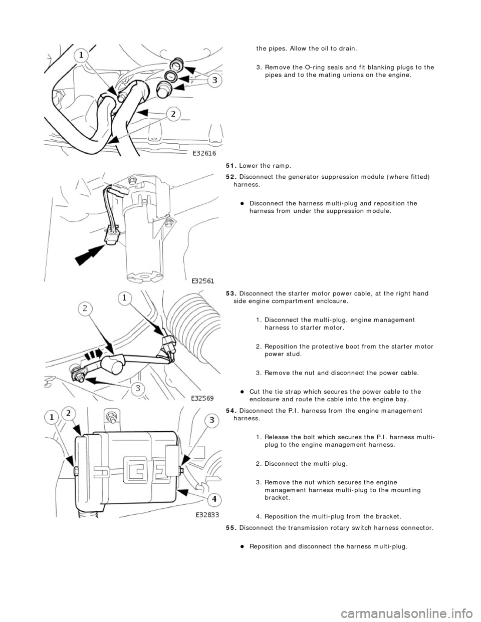
the pipes. Allow the oil to drain.
3. Remove the O-ring seals and fit blanking plugs to the
pipes and to the mating unions on the engine.
51. Lower the ramp.
52. Disconnect the generator suppres sion module (where fitted)
harness.
Disconnect the harness multi-plug and reposition the
harness from under the suppression module.
53. Disconnect the starter motor power cable, at the right hand
side engine compartment enclosure.
1. Disconnect the multi-plug, engine management harness to starter motor.
2. Reposition the protective boot from the starter motor
power stud.
3. Remove the nut and disc onnect the power cable.
Cut the tie strap which secures the power cable to the
enclosure and route the cable into the engine bay.
54. Disconnect the P.I. harness from the engine management
harness.
1. Release the bolt which secures the P.I. harness multi-plug to the engine management harness.
2. Disconnect the multi-plug.
3. Remove the nut which secures the engine management harness multi-plug to the mounting
bracket.
4. Reposition the multi-plug from the bracket.
55. Disconnect the transmission rota ry switch harness connector.
Reposition and disconnect the harness multi-plug.
Page 965 of 2490

Engine Cooling - Coolant Outlet Pipe
Re
moval and Installation
Remov
al
Installation
1.
O
pen the engine compartment and fit paintwork protection
sheets.
2. Drain the radiator. Refer to Ge neral Procedures. Retain the
coolant drain tray in position to catch any spillage when
removing the outlet pipe.
3. Di
sconnect the hoses and multi-plug from the coolant outlet
pipe.
1. Release and reposition th e hose clip, and disconnect
the top hose.
2. Release and reposition th e hose clip, and disconnect
the heater hose.
3. Disconnect the multi-plug from the temperature sensor and unscrew the sens or from the outlet pipe.
4. Release and reposition the hose clip along the bypass
hose.
4. R
emove the coolant outlet pipe.
1. Remove the four bolts which secure the outlet pipe.
2. Remove the outlet pipe from the bypass hose and
from the cylinder heads.
5. Remove and discard the sealing rings from the outlet pipe
grooves.
1. Installation is the reverse of the remova l procedure. Use new
sealing rings on the coolant outlet pipe.
2. Tighten the coolant outlet pipe bolts to 10-14 Nm If replacing
the coolant temperature sensor, tighten to 15-19 Nm.
3. Refill the cooling system as de scribed in General Procedures.