fuse diagram JAGUAR X308 1998 2.G User Guide
[x] Cancel search | Manufacturer: JAGUAR, Model Year: 1998, Model line: X308, Model: JAGUAR X308 1998 2.GPages: 2490, PDF Size: 69.81 MB
Page 1160 of 2490
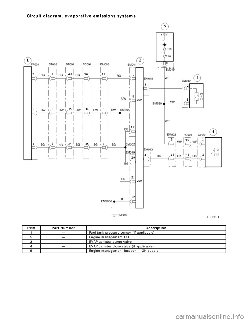
Ite
m
Part
Number
Descr
iption
1—Fu
el tank pressure sensor (if applicable)
2—Engine m
anagement ECU
3—EVAP canister purge va
lve
4—EVAP ca
nister close valve (if applicable)
5—Engine
mana
gement fusebox - IGN supply
Circuit diagram
,
evaporative emissions systems
Page 1182 of 2490
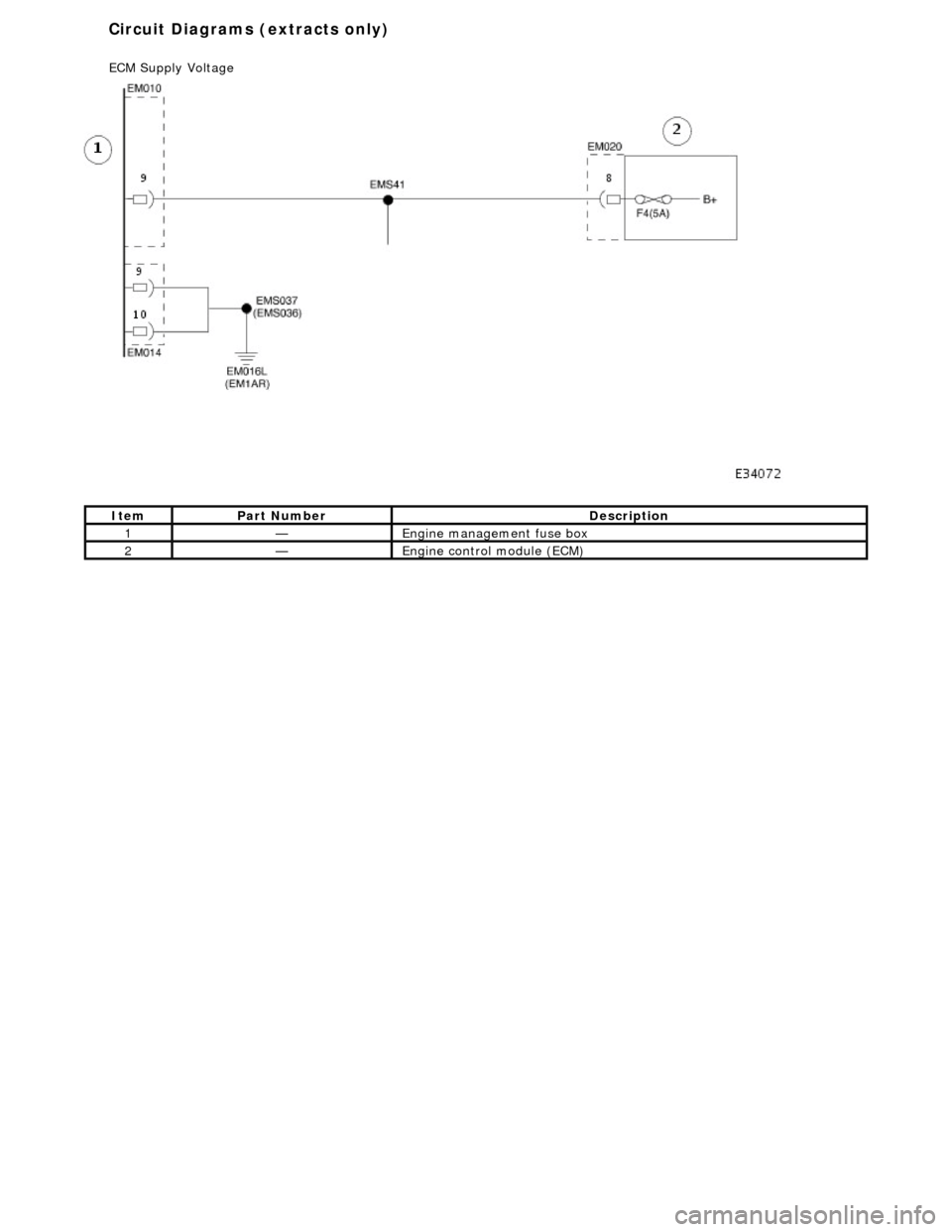
Ite
m
Par
t
Number
De
scr
iption
1—Engine
management fuse box
2—Engine
control module (E
CM)
Circuit Diagrams (extracts only)
ECM Su
pply Voltage
Page 1208 of 2490
Yes
R
EPAIR the short circuit. For addi
tional information, refer to the wiring diagrams. CLEAR the DTC.
TEST the system for normal operation.
No GO to A3
.
A3: CHECK THE MAF SENSO
R SENS
E CIRCUIT FOR SHORT TO GROUND
• NO
TE: The short to GROUND may be intermittent. Move the
wiring to attempt to reproduce the conditions under which
the DTC was logged, and visually inspect the harness for any signs of chafing, see "visual inspection chart".
Turn the ignition swit
ch to the OFF
position.
1
Measure t
he resistance between PI35, pin 02 (GY) and GROUND.
2
Is t
he resistance less than 10,000 ohms?
Yes REPAIR the short circuit. For addi tional information, refer to the wiring diagrams. CLEAR the DTC.
TEST the system for normal operation.
No GO to A4
.
A4: CHEC K THE MA
F SENSOR SUPPLY CIRCUIT VOLTAGE
Re
conn
ect the ECM electrical connector, EM12.
1
Turn the ignition swi
t
ch to the ON
position.
2
Me
asure the voltage between the MAF sensor electrical connector, PI35, pin 01 (WU) and GROUND.
3
Is the vol
t
age greater than 10 volts?
Yes GO to A5
.
No
REP
AIR the circuit between the MAF sensor electric
al connector, PI35, pin 01 (WU) and BATTERY. This
circuit includes the EMS control rela y, fuse 12 of the EMS fuse board, and splices in the harness. For
additional information, refer to the wiring diagrams. CLEAR the DT C. TEST the system for normal
operation.
A5: CHECK THE MAF SENSO
R SUPPLY CIRCUIT FOR HIGH RESISTANCE
Di
sc
onnect the battery negative terminal.
1
Di
sc
onnect the EMS fuse board electrical connector, EM20.
2
Meas
ure t
he resistance between EM20,
pin 10 (WU) and PI35, pin 01 (WU).
3
Is the res
istance greater than 5 ohms?
Yes REPAIR the high resistance circuit. For additional information, refer to the wiring diagrams. CLEAR the
DTC. TEST the system for normal operation.
No INSTALL a new MAF sensor.
REFER to Mass Air Flow (MAF) Sensor
in this
section.
CLEAR the DTC. TEST the system for normal operation.
P INPOINT TES
T B : DTC P0111, P0112, P0113;
INTAKE AIR TEMPERATURE (IAT) SENSOR
RANGE/PERFORMANCE, HIGH/LOW VOLTAGE
•
NOTE: Before commencing this
test, check the air filter for blockage and the engine air intake and breather systems for
leaks.
TE S
T
CONDITIONS
D E
TAILS/RESULTS/ACTIONS
B1: CHECK
THE IAT SENSOR
SENS
E CIRCUIT FOR HIGH RESISTANCE
Disc
onnect the battery negative terminal.
1
D
i
sconnect the ECM electrical connector, EM12.
2
Di
sc
onnect the MAF sensor electrical connector, PI35.
3
Me
asure
the resistance between EM12, pin 12 (UP) and PI35, pin 03 (UP).
4
Is th
e res
istance greater than 5 ohms?
Yes REPAIR the high resistance circui t. For additional information, refer to the wiring diagrams. CLEAR
the DTC. TEST the system for normal operation.
No GO to B2
.
B2: CHECK
THE IAT SENSOR SENSE CIRCUIT FOR SHORT TO HIGH VOLTAGE
R
e
connect the battery negative terminal.
1
Turn the ignition swi
t
ch to the ON
position.
2
Measure the voltage between PI 35,
pin 03 (UP) and GROUND.
3
Page 1211 of 2490
Is
the resistance less than 10,000 ohms?
Yes REPAIR the short circuit. For addi tional information, refer to the wiring diagrams. CLEAR the DTC.
TEST the system for normal operation.
No GO to E4
.
E4
: CHECK THE H02S GROUND
CIRCUIT FOR OPEN CIRCUIT
Re
connect the ECM electrical connector, EM12.
1
Meas
ure the resistance between EM21, pin 04 (BRD) and GROUND.
2
Is th
e resistance greater than 5 ohms?
Yes
REPAIR the circuit (this is a braide d lead which would require different repair techniques to standard
wiring). For additional information, refer to the wiring diagrams. CL EAR the DTC. TEST the system for
normal operation.
No INSTALL a new H02S.
REFER to Heated Oxygen Sensor (HO2S) RH
in this section.
CLEAR the DTC. TEST the syst em for normal operation.
PI
NPOINT TEST F : DTC P0133, P0135; RIGHT-HAND H02S HEATER CIRCUIT MALFUNCTION
TE
ST
CONDITIONS
D
ETAILS/RESULTS/ACTIONS
F1:
CHECK THE H02S HEATER POWER SUPPLY CIRCUIT
D
isconnect the H02S electrical connector, EM21.
1
Turn the ignition swi
tch to the ON
position.
2
Meas
ure the voltage between EM21, pin 02 (WP) and GROUND.
3
Is the vol
tage greater than 10 volts?
Yes GO to F2
.
No
REPAIR the circuit. This circuit in cludes the EMS control relay and fu se 14 of the EMS fuse board. For
additional information, refer to the wiring diagrams. CLEAR the DT C. TEST the system for normal
operation.
F2: CHECK THE H02
S HEATER CONTROL CI
RCUIT FROM ECM FOR HIGH RESISTANCE
Di
sconnect the battery negative terminal.
1
D
isconnect the ECM electrical connector, EM15.
2
Me
asure the resistance between EM15, pin 02 (PU) and EM21, pin 01 (PU).
3
Is th
e resistance greater than 5 ohms?
Yes REPAIR the high resistance circui t. For additional information, refer to the wiring diagrams. CLEAR
the DTC. TEST the system for normal operation.
No GO to F3
.
F3: CHECK THE H02
S HEATER CONTROL CIRCUI
T FROM ECM FOR SHORT TO HIGH VOLTAGE
R
econnect the battery negative terminal.
1
Turn the ignition swi
tch to the ON
position.
2
Meas
ure the voltage between EM21, pin 01 (PU) and GROUND.
3
Is th
e voltage greater than 3 volts?
Yes REPAIR the short circuit. For addi tional information, refer to the wiring diagrams. CLEAR the DTC.
TEST the system for normal operation.
No GO to F4
.
F4: CHECK THE H02
S HEATER CONTROL CI
RCUIT FROM ECM FOR SHORT TO GROUND
Turn the ignition swi
tch to the OFF
position.
1
Meas
ure the resistance between EM21, pin 01 (PU) and GROUND.
2
Is
the resistance less than 10,000 ohms?
Yes REPAIR the short circuit. For addi tional information, refer to the wiring diagrams. CLEAR the DTC.
TEST the system for normal operation.
No INSTALL a new H02S.
REFER to Heated Oxygen Sensor (HO2S) RH
in this section.
Page 1213 of 2490
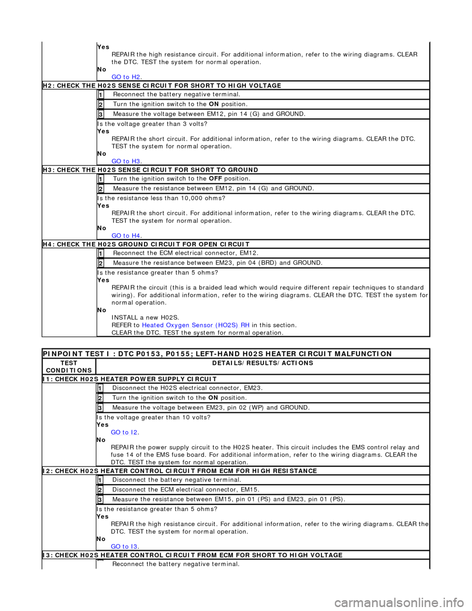
Yes
REPAIR the high resistance circui t. For additional information, refer to the wiring diagrams. CLEAR
the DTC. TEST the system for normal operation.
No GO to H2
.
H
2: CHECK THE H02S SENSE CIRCUIT FOR SHORT TO HIGH VOLTAGE
R
econnect the battery negative terminal.
1
Turn the ignition swi
tch to the ON
position.
2
M
easure the voltage between EM12, pin 14 (G) and GROUND.
3
Is th
e voltage greater than 3 volts?
Yes REPAIR the short circuit. For addi tional information, refer to the wiring diagrams. CLEAR the DTC.
TEST the system for normal operation.
No GO to H3
.
H
3: CHECK THE H02S SENSE CIRCUIT FOR SHORT TO GROUND
Turn the ignition swi
tch to the OFF
position.
1
Meas
ure the resistance between EM12, pin 14 (G) and GROUND.
2
Is
the resistance less than 10,000 ohms?
Yes REPAIR the short circuit. For addi tional information, refer to the wiring diagrams. CLEAR the DTC.
TEST the system for normal operation.
No GO to H4
.
H4:
CHECK THE H02S GROUND CIRCUIT FOR OPEN CIRCUIT
Re
connect the ECM electrical connector, EM12.
1
Meas
ure the resistance between EM23, pin 04 (BRD) and GROUND.
2
Is th
e resistance greater than 5 ohms?
Yes REPAIR the circuit (this is a braide d lead which would require different repair techniques to standard
wiring). For additional information, refer to the wiring diagrams. CL EAR the DTC. TEST the system for
normal operation.
No INSTALL a new H02S.
REFER to Heated Oxygen Sensor (HO2S) RH
in this section.
CLEAR the DTC. TEST the syst em for normal operation.
P
INPOINT TEST I : DTC P0153, P0155; LEFT-HAND H02S HEATER CIRCUIT MALFUNCTION
TE
ST
CONDITIONS
D
ETAILS/RESULTS/ACTIONS
I
1: CHECK H02S HEATER POWER SUPPLY CIRCUIT
D
isconnect the H02S electrical connector, EM23.
1
Turn the ignition swi
tch to the
ON position.
2
Meas
ure the voltage between EM23, pin 02 (WP) and GROUND.
3
Is the vol
tage greater than 10 volts?
Yes GO to I2
.
No
REPAIR the power supply circuit to the H02S heater. This circuit includes the EMS control relay and
fuse 14 of the EMS fuse board. For additional info rmation, refer to the wiring diagrams. CLEAR the
DTC. TEST the system for normal operation.
I
2: CHECK H02S HEATER CONTROL CIRC
UIT FROM ECM FOR HIGH RESISTANCE
Di
sconnect the battery negative terminal.
1
D
isconnect the ECM electrical connector, EM15.
2
Meas
ure the resistance between EM15,
pin 01 (PS) and EM23, pin 01 (PS).
3
Is th
e resistance greater than 5 ohms?
Yes REPAIR the high resistance circuit. For additional information, refer to the wiring diagrams. CLEAR the
DTC. TEST the system for normal operation.
No GO to I3
.
I
3: CHECK H02S HEATER CONTROL CIRCUIT
FROM ECM FOR SHORT TO HIGH VOLTAGE
R
econnect the battery negative terminal.
Page 1218 of 2490
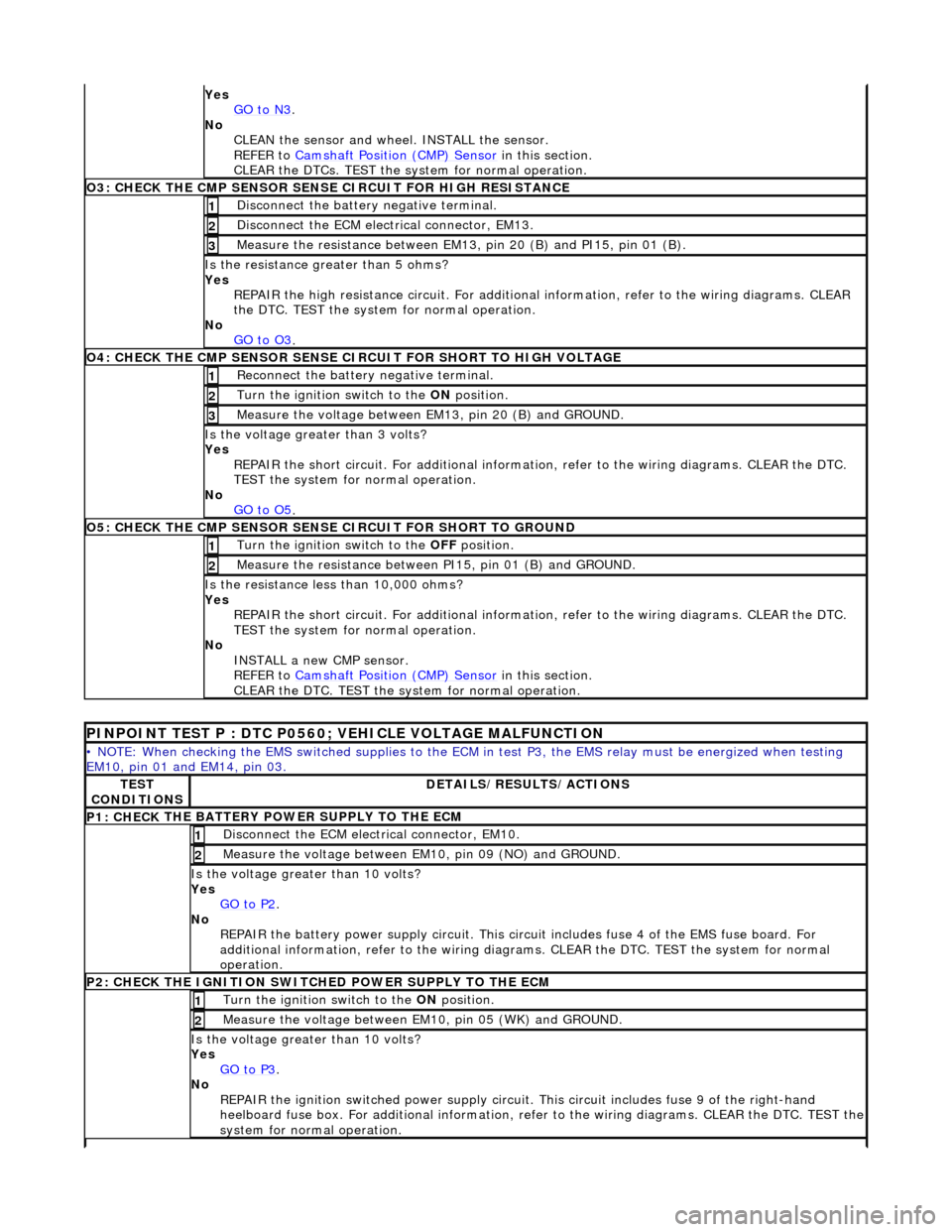
Yes
GO to N3.
No
CLEAN th
e sensor and whee
l. INSTALL the sensor.
REFER to Camshaft Position (CMP) Sensor
in this
section.
CLEAR the DTCs. TEST the system for normal operation.
O3: CHECK THE CM P SEN
SOR SENS
E CIRCUIT FOR HIGH RESISTANCE
Disc
onnect the battery negative terminal.
1
D
i
sconnect the ECM electrical connector, EM13.
2
Meas
ure t
he resistance between EM13, pin 20 (B) and PI15, pin 01 (B).
3
Is the res
istance greater than 5 ohms?
Yes REPAIR the high resistance circui t. For additional information, refer to the wiring diagrams. CLEAR
the DTC. TEST the system for normal operation.
No GO to O3
.
O4: CHECK THE CM P SEN
SOR SENSE CI
RCUIT FOR SHORT TO HIGH VOLTAGE
Re
connect the battery negative terminal.
1
Turn the ignition swi
t
ch to the ON
position.
2
Me
asure the voltage between EM13, pin 20 (B) and GROUND.
3
Is th
e volt
age greater than 3 volts?
Yes REPAIR the short circuit. For addi tional information, refer to the wiring diagrams. CLEAR the DTC.
TEST the system for normal operation.
No GO to O5
.
O5: CH ECK THE CM
P SENSOR SENSE CIRCUIT FOR SHORT TO GROUND
Turn the ignition swi
t
ch to the OFF
position.
1
Me
asure the resistance between PI15, pin 01 (B) and GROUND.
2
Is
t
he resistance less than 10,000 ohms?
Yes REPAIR the short circuit. For addi tional information, refer to the wiring diagrams. CLEAR the DTC.
TEST the system for normal operation.
No INSTALL a new CMP sensor.
REFER to Camshaft Position (CMP) Sensor
in this
section.
CLEAR the DTC. TEST the system for normal operation.
P I
NPOINT TEST P : DTC P0560; VEHICLE VOLTAGE MALFUNCTION
•
NOTE
: When checking the EMS switched supplies to the ECM
in test P3, the EMS relay must be energized when testing
EM10, pin 01 and EM14, pin 03.
TE S
T
CONDITIONS
D E
TAILS/RESULTS/ACTIONS
P1: CHECK
THE BATTERY POWER SUPPLY TO THE ECM
D
i
sconnect the ECM electrical connector, EM10.
1
Measure the
voltage between EM 10,
pin 09 (NO) and GROUND.
2
Is the vol
t
age greater than 10 volts?
Yes GO to P2
.
No
REPAIR th
e battery power supply circ
uit. This circuit includes fuse 4 of the EMS fuse board. For
additional information, refer to the wiring diagrams. CLEAR the DT C. TEST the system for normal
operation.
P2: CHECK
THE IGNITION SWITCH
ED POWER SUPPLY TO THE ECM
Turn the ignition swit
ch to the
ON position.
1
Meas
ure t
he voltage between EM10, pin 05 (WK) and GROUND.
2
Is the vol
t
age greater than 10 volts?
Yes GO to P3
.
No
REP
AIR the ignition switched power supply circuit. This circuit includes fuse 9 of the right-hand
heelboard fuse box. For a dditional information, refer to the wiri ng diagrams. CLEAR the DTC. TEST the
system for normal operation.
Page 1219 of 2490
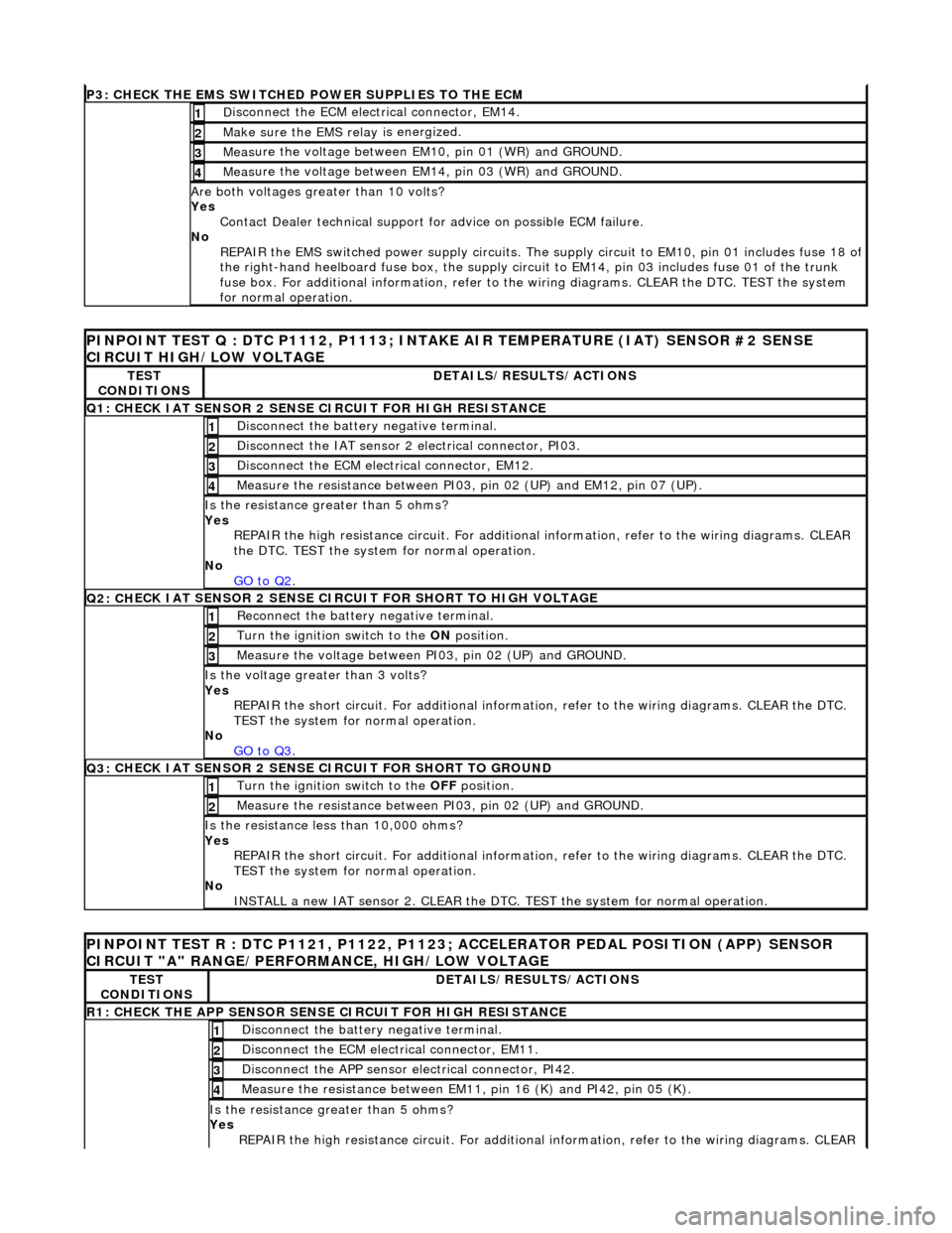
P3: CHECK
THE EMS SWITCHED
POWER SUPPLIES TO THE ECM
D
isconnect the ECM electrical connector, EM14.
1
Make sure the EMS re
lay i
s energized.
2
Meas
ure the voltage between EM10, pin 01 (WR) and GROUND.
3
Meas
ure the voltage between EM14, pin 03 (WR) and GROUND.
4
Are both
voltages greater than 10 volts?
Yes Contact Dealer technical support for advice on possible ECM failure.
No REPAIR the EMS switched power supply circuits. The su pply circuit to EM10, pin 01 includes fuse 18 of
the right-hand heelboard fuse box, the supply circuit to EM14, pin 03 includes fuse 01 of the trunk
fuse box. For additional information, refer to th e wiring diagrams. CLEAR the DTC. TEST the system
for normal operation.
PI
NPOINT TEST Q : DTC P1112, P1113; INTAKE
AIR TEMPERATURE (IAT) SENSOR #2 SENSE
CIRCUIT HIGH/LOW VOLTAGE
TE
ST
CONDITIONS
D
ETAILS/RESULTS/ACTIONS
Q1:
CHECK IAT SENSOR 2 SENSE CIRCUIT FOR HIGH RESISTANCE
Di
sconnect the battery negative terminal.
1
Di
sconnect the IAT sensor 2 electrical connector, PI03.
2
D
isconnect the ECM electrical connector, EM12.
3
Me
asure the resistance between PI03, pin 02 (UP) and EM12, pin 07 (UP).
4
Is th
e resistance greater than 5 ohms?
Yes REPAIR the high resistance circui t. For additional information, refer to the wiring diagrams. CLEAR
the DTC. TEST the system for normal operation.
No GO to Q2
.
Q2: CH
ECK IAT SENSOR 2 SENSE CIRC
UIT FOR SHORT TO HIGH VOLTAGE
R
econnect the battery negative terminal.
1
Turn the ignition swi
tch to the ON
position.
2
Measure the
voltage between PI
03, pin 02 (UP) and GROUND.
3
Is th
e voltage greater than 3 volts?
Yes REPAIR the short circuit. For addi tional information, refer to the wiring diagrams. CLEAR the DTC.
TEST the system for normal operation.
No GO to Q3
.
Q3:
CHECK IAT SENSOR 2 SENSE CIRCUIT FOR SHORT TO GROUND
Turn the ignition swi
tch to the OFF
position.
1
Meas
ure the resistance between PI03, pin 02 (UP) and GROUND.
2
Is
the resistance less than 10,000 ohms?
Yes REPAIR the short circuit. For addi tional information, refer to the wiring diagrams. CLEAR the DTC.
TEST the system for normal operation.
No INSTALL a new IAT sensor 2. CLEAR the DTC. TEST the system for normal operation.
P
INPOINT TEST R : DTC P1121, P1122, P1123;
ACCELERATOR PEDAL POSITION (APP) SENSOR
CIRCUIT "A" RANGE/PERFORMANCE, HIGH/LOW VOLTAGE
TE
ST
CONDITIONS
D
ETAILS/RESULTS/ACTIONS
R1: CHECK THE APP
SENSOR SENSE CIRCUIT FOR HIGH RESISTANCE
Di
sconnect the battery negative terminal.
1
D
isconnect the ECM electrical connector, EM11.
2
Di
sconnect the APP sensor electrical connector, PI42.
3
Meas
ure the resistance between EM11, pin 16 (K) and PI42, pin 05 (K).
4
Is th
e resistance greater than 5 ohms?
Yes REPAIR the high resistance circui t. For additional information, refer to the wiring diagrams. CLEAR
Page 1222 of 2490
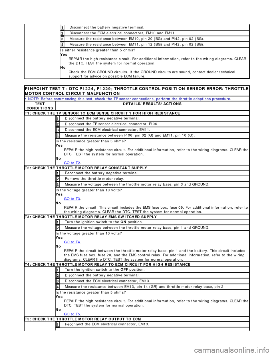
Disc
onnect the battery negative terminal.
1
D
i
sconnect the ECM electrical connectors, EM10 and EM11.
2
Meas
ure t
he resistance between EM10,
pin 20 (BG) and PI42, pin 02 (BG).
3
Measure t
he resistance between EM11,
pin 12 (BG) and PI42, pin 02 (BG).
4
Is either resistance greater
than 5 ohms?
Yes REPAIR the high resistance circui t. For additional information, refer to the wiring diagrams. CLEAR
the DTC. TEST the system for normal operation.
No Check the ECM GROUND circuits. If the GROUND circuits are sound, contact dealer technical
support for advice on possible ECM failure.
PINPOINT TES
T T : DTC P1224, P1229; THROTTLE
CONTROL POSITION SENSOR ERROR/THROTTLE
MOTOR CONTROL CIRCUIT MALFUNCTION
•
NOTE: Before commencing this test, check the TP sensor
connections, perform the throttle adaptions procedure.
TES
T
CONDITIONS
D E
TAILS/RESULTS/ACTIONS
T
1: CH
ECK THE TP SENSOR TO ECM SE
NSE CIRCUIT 1 FOR HIGH RESISTANCE
Disc
onnect the battery negative terminal.
1
Disc
onne
ct the TP sensor electrical connector, PI06.
2
D
i
sconnect the ECM electrical connector, EM11.
3
Me
asure
the resistance between PI06, pin 02 (G) and EM11, pin 10 (G).
4
Is th
e res
istance greater than 5 ohms?
Yes REPAIR the high resistance circuit. For additional information, refer to the wiring diagrams. CLEAR the
DTC. TEST the system for normal operation.
No GO to T2
.
T2
: CHECK THE THROTTLE MOTOR RELAY CONSTANT SUPPLY
R
e
connect the battery negative terminal.
1
R
e
move the thrott
le motor relay.
2
Measure t
he voltage between the throttle
motor relay base, pin 3 and GROUND.
3
Is the volt
age greater than 10 volts?
Yes GO to T3
.
No
R
EPAIR the circuit. This ci
rcuit includes the EMS fuse box, fuse 09. For addi tional information, refer to
the wiring diagrams. CLEAR the DTC. TE ST the system for normal operation.
T3
: CHECK THE THROTTLE MOTOR
RELAY EMS SWITCHED SUPPLY
Turn the ignition swit
ch to the
ON position.
1
Meas ure t
he voltage between the throttle
motor relay base, pin 1 and GROUND.
2
Is the volt
age greater than 10 volts?
Yes GO to T4
.
No
REP
AIR the circuit between the throttle motor relay
base, pin 1 and the battery. This circuit includes
the EMS fuse box, fuse 20, and the EMS control relay. For addition al information, refer to the wiring
diagrams. CLEAR the DTC. TEST th e system for normal operation.
T4
: CHECK THE THROTTLE MOTOR RELAY TO
ECM CIRCUIT FOR HIGH RESISTANCE
Turn the ignition swit
ch to the
OFF position.
1
Disc
onnect the battery negative terminal.
2
Di
sconnect the ECM electrical connector, EM13.
3
Measure t
he resistance between EM13, pin 14 (G
R) and throttle motor relay base, pin 2.
4
Is the res
istance greater than 5 ohms?
Yes REPAIR the high resistance circuit. For additional information, refer to the wiring diagrams. CLEAR the
DTC. TEST the system for normal operation.
No GO to T5
.
T5
: CHECK THE THROTTLE MOTOR RELAY OUTPUT TO ECM
Re
conn
ect the ECM electrical connector, EM13.
1
Page 1230 of 2490
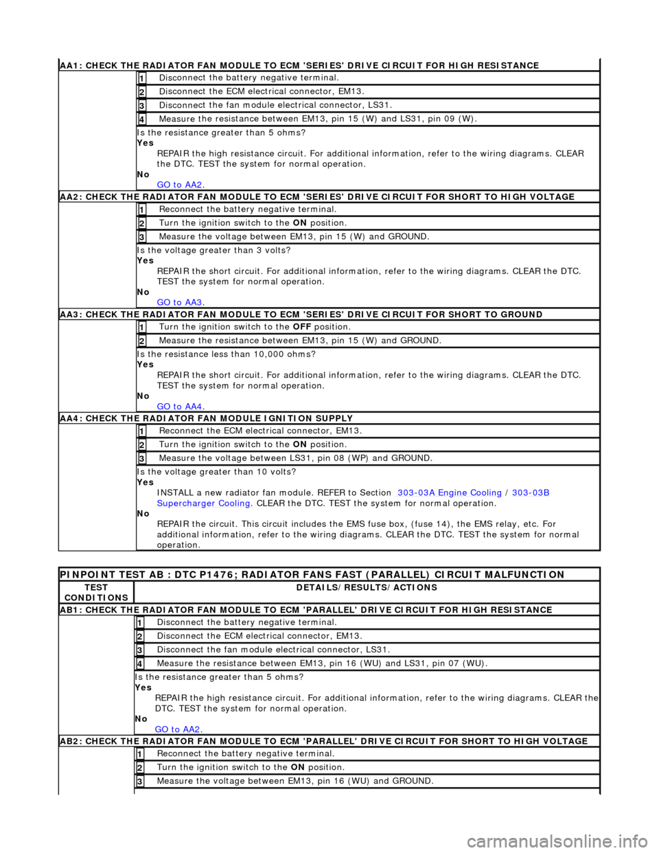
AA1: CHECK THE RA
DIATOR FAN MODULE TO ECM
'SERIES' DRIVE CIRCUIT FOR HIGH RESISTANCE
Disc
onnect the battery negative terminal.
1
D
i
sconnect the ECM electrical connector, EM13.
2
Disc
onne
ct the fan module electrical connector, LS31.
3
Meas
ure t
he resistance between EM13, pin 15 (W) and LS31, pin 09 (W).
4
Is th
e res
istance greater than 5 ohms?
Yes REPAIR the high resistance circui t. For additional information, refer to the wiring diagrams. CLEAR
the DTC. TEST the system for normal operation.
No GO to AA2
.
AA2: CHECK THE RA
DIATOR FAN MODULE TO ECM 'SER
IES' DRIVE CIRCUIT FOR SHORT TO HIGH VOLTAGE
Re
connect the battery negative terminal.
1
Turn the ignition swit
ch to the
ON position.
2
Measure t
he voltage between EM13, pin 15 (W) and GROUND.
3
Is the volt
age greater than 3 volts?
Yes REPAIR the short circuit. For addi tional information, refer to the wiring diagrams. CLEAR the DTC.
TEST the system for normal operation.
No GO to AA3
.
AA3: CHECK THE R A
DIATOR FAN MODULE TO ECM
'SERIES' DRIVE CIRCUIT FOR SHORT TO GROUND
Turn the ignition swit
ch to the
OFF position.
1
Meas ure t
he resistance between EM13, pin 15 (W) and GROUND.
2
Is
t
he resistance less than 10,000 ohms?
Yes
REPAIR the short circuit. For addi tional information, refer to the wiring diagrams. CLEAR the DTC.
TEST the system for normal operation.
No GO to AA4
.
AA4:
CHECK THE RADIATOR FAN MODULE IGNITION SUPPLY
Reconn
ect the ECM electrical connector, EM13.
1
Turn the ignition swit
ch to the
ON position.
2
Measure the voltage between LS 31,
pin 08 (WP) and GROUND.
3
Is the vol
t
age greater than 10 volts?
Yes INSTALL a new radiator fan module. REFER to Section 303
-03
A Engine Cooling
/
303-03B Supercharger Cooli
ng
. CLEA
R the DTC. TEST the sy stem f
or normal operation.
No REPAIR the circuit. This circui t includes the EMS fuse box, (f use 14), the EMS relay, etc. For
additional information, refer to the wiring diagrams. CLEAR the DT C. TEST the system for normal
operation.
PINPOINT TE ST
AB : DTC P1476; RADIATOR
FANS FAST (PARALLEL) CIRCUIT MALFUNCTION
TES
T
CONDITIONS
D E
TAILS/RESULTS/ACTIONS
AB1
:
CHECK THE RADIATOR FAN MODULE TO ECM
'PARALLEL' DRIVE CIRCUIT FOR HIGH RESISTANCE
Disc
onnect the battery negative terminal.
1
D
i
sconnect the ECM electrical connector, EM13.
2
Disc
onne
ct the fan module electrical connector, LS31.
3
Meas
ure t
he resistance between EM13, pin 16 (WU) and LS31, pin 07 (WU).
4
Is th
e res
istance greater than 5 ohms?
Yes REPAIR the high resistance circuit. For additional information, refer to the wiring diagrams. CLEAR the
DTC. TEST the system for normal operation.
No GO to AA2
.
AB2:
CHECK THE RADIATOR FAN MODULE TO ECM 'PARALLEL' DRIVE CIRCUIT FOR SHORT TO HIGH VOLTAGE
R
e
connect the battery negative terminal.
1
Turn the ignition swi
t
ch to the ON
position.
2
Measure t
he voltage between EM13, pin 16 (WU) and GROUND.
3
Page 1231 of 2490
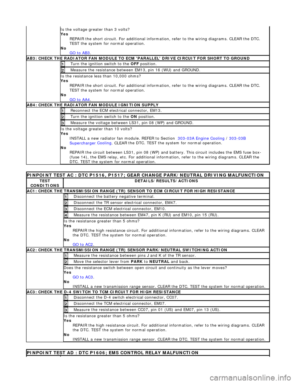
Is th
e voltage greater than 3 volts?
Yes REPAIR the short circuit. For addi tional information, refer to the wiring diagrams. CLEAR the DTC.
TEST the system for normal operation.
No GO to AB3
.
AB3
: CHECK THE RADIATOR FAN MODULE TO ECM
'PARALLEL' DRIVE CIRCUIT FOR SHORT TO GROUND
Turn the ignition swi
tch to the OFF
position.
1
Meas
ure the resistance between EM13, pin 16 (WU) and GROUND.
2
Is
the resistance less than 10,000 ohms?
Yes
REPAIR the short circuit. For addi tional information, refer to the wiring diagrams. CLEAR the DTC.
TEST the system for normal operation.
No GO to AA4
.
AB4
: CHECK THE RADIATOR FAN MODULE IGNITION SUPPLY
Re
connect the ECM electrical connector, EM13.
1
Turn the ignition swi
tch to the ON
position.
2
Measure the
voltage between LS
31, pin 08 (WP) and GROUND.
3
Is the vol
tage greater than 10 volts?
Yes INSTALL a new radiator fan module. REFER to Section 303
-0
3A Engine Cooling
/
30
3
-03
B
Supercharger
Cooling
. CLEA
R the DTC. TEST the sy
stem for normal operation.
No REPAIR the circuit between LS31, pin 08 (WP) and battery. This circuit includes the EMS fuse box-
(fuse 14), the EMS relay, etc. For additional information, refer to the wiring diagrams. CLEAR the
DTC. TEST the system for normal operation.
P
INPOINT TEST AC : DTC P1516, P1517; GEAR
CHANGE PARK/NEUTRAL DRIVING MALFUNCTION
TE
ST
CONDITIONS
D
ETAILS/RESULTS/ACTIONS
AC1: CH
ECK THE TRANSMISSION RANGE (TR) SE
NSOR TO ECM CIRCUIT FOR HIGH RESISTANCE
Di
sconnect the battery negative terminal.
1
Di
sconnect the TR sensor el
ectrical connector, EM47.
2
D
isconnect the ECM electrical connector, EM10.
3
Meas
ure the resistance between EM47, pin K (RU) and EM10, pin 15 (RU).
4
Is th
e resistance greater than 5 ohms?
Yes REPAIR the high resistance circui t. For additional information, refer to the wiring diagrams. CLEAR
the DTC. TEST the system for normal operation.
No GO to AC2
.
AC2: CH
ECK THE TRANSMISSION RANGE (TR)
SENSOR PARK/NEUTRAL SWITCHING ACTION
Meas
ure the resistance between pi
ns J and K of the TR sensor.
1
Mo
ve the selector lever from
PARK to NEUTRAL and back.
2
D
oes the resistance switch between open ci
rcuit and continuity as the lever moves?
Yes GO to AC3
.
No
INSTALL a new transmission range sensor. CLEAR th e DTC. TEST the system for normal operation.
AC3: CH
ECK THE D-4 SWITCH TO
TCM CIRCUIT FOR HIGH RESISTANCE
Di
sconnect the D-4 switch electrical connector, CC07.
1
Di
sconnect the TCM electrical connector, EM07.
2
Meas
ure the resistance between CC07,
pin 01 (US) and EM07, pin 13 (US).
3
Is th
e resistance greater than 5 ohms?
Yes REPAIR the high resistance circui t. For additional information, refer to the wiring diagrams. CLEAR
the DTC. TEST the system for normal operation.
No INSTALL a new transmission range sensor. CLEAR th e DTC. TEST the system for normal operation.
P
INPOINT TEST AD : DTC P1606;
EMS CONTROL RELAY MALFUNCTION