ignition JAGUAR X308 1998 2.G User Guide
[x] Cancel search | Manufacturer: JAGUAR, Model Year: 1998, Model line: X308, Model: JAGUAR X308 1998 2.GPages: 2490, PDF Size: 69.81 MB
Page 437 of 2490
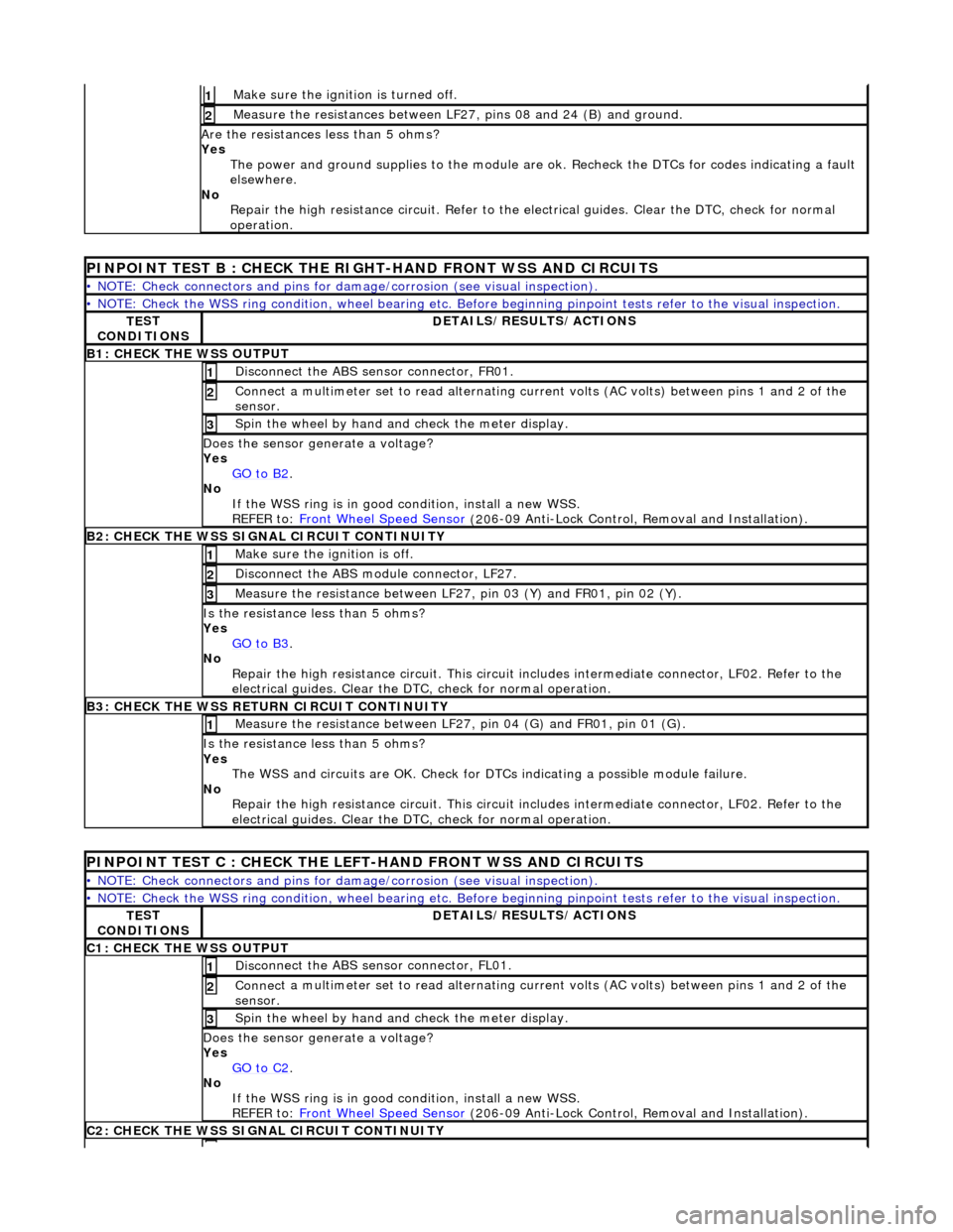
Make sure the ignition is turned off. 1
Meas
ure the resistances between LF27,
pins 08 and 24 (B) and ground.
2
Are
the resistances less than 5 ohms?
Yes The power and ground supplies to the module are ok . Recheck the DTCs for codes indicating a fault
elsewhere.
No Repair the high resistance circui t. Refer to the electrical guides. Clear the DTC, check for normal
operation.
PINPOINT TE
ST B : CHECK THE RIGHT-HAND FRONT WSS AND CIRCUITS
•
NOTE: Check connectors and pins for damage/corrosion
(see visual inspection).
•
NOTE: Check the WSS ring condition, whee
l bearing etc. Before beginning pinpoint test s refer to the visual inspection.
TE
ST
CONDITIONS
D
ETAILS/RESULTS/ACTIONS
B1: CHECK
THE WSS OUTPUT
Disc
onnect the ABS sensor connector, FR01.
1
Connec
t a multimeter set
to read alternating curr ent volts (AC volts) between pins 1 and 2 of the
sensor.
2
Spin
the wheel by hand and check the meter display.
3
Doe
s the sensor generate a voltage?
Yes GO to B2
.
No
If the WSS ring is in good condition, install a new WSS.
REFER to: Front Wheel Speed Sensor
(20
6-09 Anti-Lock Control, Removal and Installation).
B2:
CHECK THE WSS SIGNAL CIRCUIT CONTINUITY
Make sure the ignition is off. 1
Di
sconnect the ABS module connector, LF27.
2
Meas
ure the resistance between LF27
, pin 03 (Y) and FR01, pin 02 (Y).
3
I
s the resistance less than 5 ohms?
Yes GO to B3
.
No
Repair the high resistance circui t. This circuit includes intermediate connector, LF02. Refer to the
electrical guides. Clear the DTC, check for normal operation.
B3:
CHECK THE WSS RETURN CIRCUIT CONTINUITY
Meas
ure the resistance between LF27
, pin 04 (G) and FR01, pin 01 (G).
1
I
s the resistance less than 5 ohms?
Yes The WSS and circuits are OK. Check for DTCs indicating a possible module failure.
No Repair the high resistance circui t. This circuit includes intermediate connector, LF02. Refer to the
electrical guides. Clear the DTC, check for normal operation.
P
INPOINT TEST C : CHECK THE LEFT-HAND FRONT WSS AND CIRCUITS
•
NOTE: Check connectors and pins for damage/corrosion
(see visual inspection).
•
NOTE: Check the WSS ring condition, whee
l bearing etc. Before beginning pinpoint test s refer to the visual inspection.
TE
ST
CONDITIONS
D
ETAILS/RESULTS/ACTIONS
C1
: CHECK THE WSS OUTPUT
Disc
onnect the ABS sensor connector, FL01.
1
Connec
t a multimeter set
to read alternating curr ent volts (AC volts) between pins 1 and 2 of the
sensor.
2
Spin
the wheel by hand and check the meter display.
3
Doe
s the sensor generate a voltage?
Yes GO to C2
.
No
If the WSS ring is in good condition, install a new WSS.
REFER to: Front Wheel Speed Sensor
(20
6-09 Anti-Lock Control, Removal and Installation).
C2
: CHECK THE WSS SIGNAL CIRCUIT CONTINUITY
Page 438 of 2490
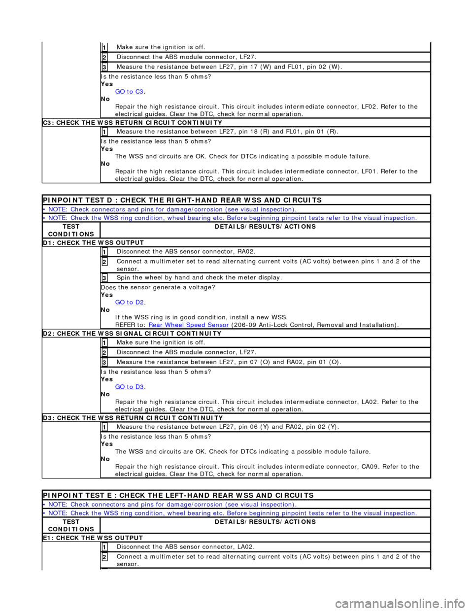
Make sure the ignition is off. 1
Disc
onnect the ABS module connector, LF27.
2
M
e
asure the resistance between LF27, pin 17 (W) and FL01, pin 02 (W).
3
I
s
the resistance less than 5 ohms?
Yes GO to C3
.
No
Re
pair the high resistance circui
t. This circuit includes intermed iate connector, LF02. Refer to the
electrical guides. Clear the DTC, check for normal operation.
C3: CH
ECK THE WSS RETURN CIRCUIT CONTINUITY
Measure
the resistance between LF27, pin 18 (R) and FL01, pin 01 (R).
1
Is
the resistance less than 5 ohms?
Yes The WSS and circuits are OK. Check for DTCs indicating a possible module failure.
No Repair the high resistance circui t. This circuit includes intermediate connector, LF01. Refer to the
electrical guides. Clear the DTC, check for normal operation.
PI
NPOINT TEST D : CHECK THE RIGH
T-HAND REAR WSS AND CIRCUITS
•
NOTE: Check connectors and pins for damage/corrosion
(see visual inspection).
• NO
TE: Check the WSS ring condition, whee
l bearing etc. Before beginning pinpoint test s refer to the visual inspection.
TES
T
CONDITIONS
D E
TAILS/RESULTS/ACTIONS
D1: CHECK
THE WSS OUTPUT
Disc
onne
ct the ABS sensor connector, RA02.
1
Connec
t
a multimeter set
to read alternating curr ent volts (AC volts) between pins 1 and 2 of the
sensor.
2
Spin
the wheel by hand and check the meter display.
3
Doe
s
the sensor generate a voltage?
Yes GO to D2
.
No
If
the WSS ring is in good condition, install a new WSS.
REFER to: Rear Wheel Speed Sensor
(206-0
9 Anti-Lock Control, Removal and Installation).
D
2
: CHECK THE WSS SIGNAL CIRCUIT CONTINUITY
Make sure the ignition is off. 1
Disc
onnect the ABS module connector, LF27.
2
Measure t
he resistance between LF27
, pin 07 (O) and RA02, pin 01 (O).
3
Is
the resistance less than 5 ohms?
Yes GO to D3
.
No Re
pair the high resistance circui
t. This circuit includes intermed iate connector, LA02. Refer to the
electrical guides. Clear the DTC, check for normal operation.
D3:
CHECK THE WSS RETURN CIRCUIT CONTINUITY
Meas
ure t
he resistance between LF27
, pin 06 (Y) and RA02, pin 02 (Y).
1
Is
the resistance less than 5 ohms?
Yes The WSS and circuits are OK. Check for DTCs indicating a possible module failure.
No Repair the high resistance circui t. This circuit includes intermediate connector, CA09. Refer to the
electrical guides. Clear the DTC, check for normal operation.
PI
NPOINT TEST E : CHECK THE LEFT-HAND REAR WSS AND CIRCUITS
•
NOTE: Check connectors and pins for damage/corrosion
(see visual inspection).
• NO
TE: Check the WSS ring condition, whee
l bearing etc. Before beginning pinpoint test s refer to the visual inspection.
TES
T
CONDITIONS
D E
TAILS/RESULTS/ACTIONS
E1
: CHECK THE W
SS OUTPUT
Disc
onne
ct the ABS sensor connector, LA02.
1
Connec
t
a multimeter set
to read alternating curr ent volts (AC volts) between pins 1 and 2 of the
sensor.
2
Page 439 of 2490
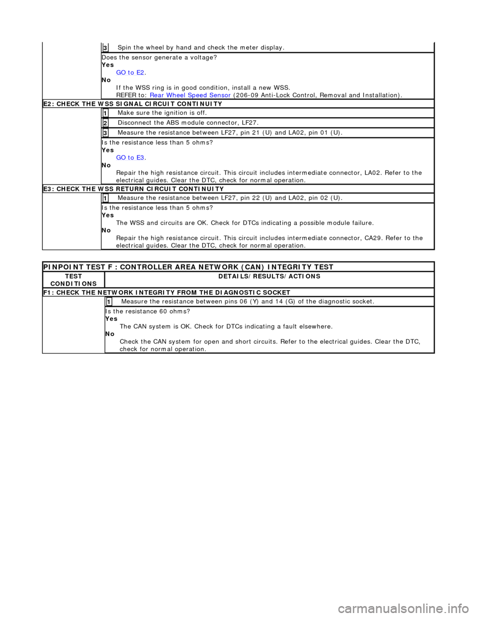
Spin
the wheel by hand and check the meter display.
3
Doe
s the sensor generate a voltage?
Yes GO to E2
.
No
If the WSS ring is in good condition, install a new WSS.
REFER to: Rear Wheel Speed Sensor
(20
6-09 Anti-Lock Control, Removal and Installation).
E2
: CHECK THE WSS SIGNAL CIRCUIT CONTINUITY
Make sure the ignition is off. 1
Di
sconnect the ABS module connector, LF27.
2
Meas
ure the resistance between LF27
, pin 21 (U) and LA02, pin 01 (U).
3
I
s the resistance less than 5 ohms?
Yes GO to E3
.
No
Repair the high resistance circui t. This circuit includes intermediate connector, LA02. Refer to the
electrical guides. Clear the DTC, check for normal operation.
E3
: CHECK THE WSS RETURN CIRCUIT CONTINUITY
Meas
ure the resistance between LF27
, pin 22 (U) and LA02, pin 02 (U).
1
I
s the resistance less than 5 ohms?
Yes The WSS and circuits are OK. Check for DTCs indicating a possible module failure.
No Repair the high resistance circui t. This circuit includes intermediate connector, CA29. Refer to the
electrical guides. Clear the DTC, check for normal operation.
P
INPOINT TEST F : CONT
ROLLER AREA NETWORK (CAN) INTEGRITY TEST
TE
ST
CONDITIONS
D
ETAILS/RESULTS/ACTIONS
F
1: CHECK THE NETWORK INTEGRITY
FROM THE DIAGNOSTIC SOCKET
M
easure the resistance between pins 06 (Y) and 14 (G) of the diagnostic socket.
1
I
s the resistance 60 ohms?
Yes The CAN system is OK. Check for DTCs indicating a fault elsewhere.
No Check the CAN system for open an d short circuits. Refer to the electrical guides. Clear the DTC,
check for normal operation.
Page 460 of 2490
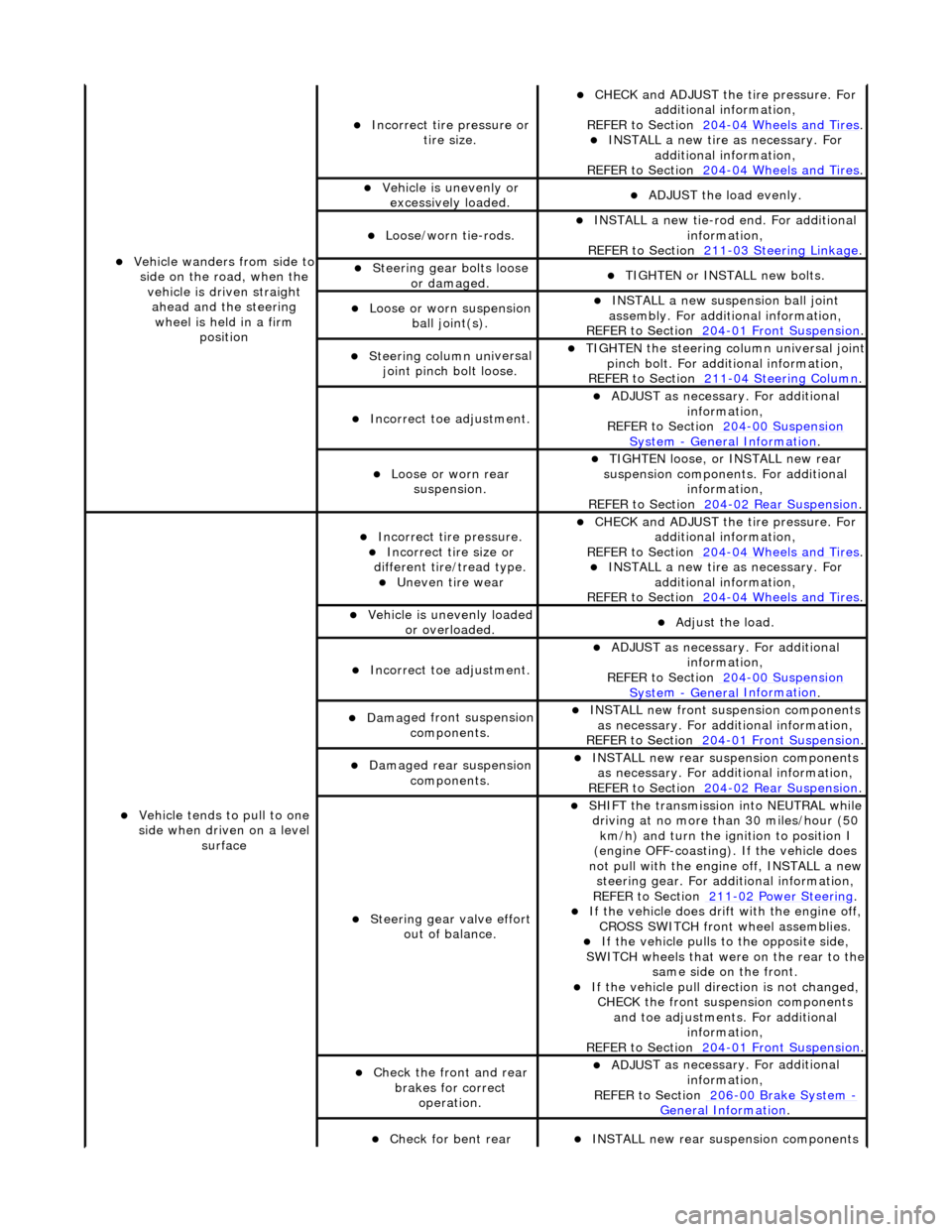
Vehicl
e wanders from side to
side on the road, when the vehicle is driven straight ahead and the steering wheel is held in a firm position
Incorrect ti re
pressure or
tire size.
CHECK and ADJ
UST the tire pressure. For
additional information,
REFER to Section 204
-0 4
Wheels and Tires
. IN
ST
ALL a new tire as necessary. For
additional information,
REFER to Section 204
-0 4
Wheels and Tires
.
Vehi
cl
e is unevenly or
excessively loaded.
A D
JUST the load evenly.
Loose/worn ti
e-
rods.
INST
ALL a ne
w tie-rod
end. For additional
information,
REFER to Section 211
-0 3
Steering Linkage
.
Steeri
ng gear bolts loose
o
r damaged.
TIGHTE
N or INSTALL
new bolts.
Loose or worn suspensi
on
ball jo
int(s).
INST
ALL a ne
w suspension ball joint
assembly. For additional information,
REFER to Section 204
-01 Fron
t Suspension
.
Steeri
ng column uni
versal
joint pinch bolt loose.
TI G
HTEN the steering column universal joint
pinch bolt. For additi onal information,
REFER to Section 211
-0 4
Steering Column
.
Incorre
ct
toe adjustment.
ADJUS
T as necessary. For additional
information,
REFER to Section 204
-00 Sus
pension
Sy
ste
m
- General
Information
.
Loose or worn rear
susp
ension.
TIGHTEN
loose, or IN
STALL new rear
suspension components. For additional information,
REFER to Section 204
-0 2
Rear Suspension
.
Vehicle t
e
nds to pull to one
side when driven on a level surface
Incorrect ti
re pressure.
Incorrect
ti
re size or
different tire/tread type.
Uneven tire wear
CHECK and ADJ
UST the tire pressure. For
additional information,
REFER to Section 204
-0 4
Wheels and Tires
. IN
ST
ALL a new tire as necessary. For
additional information,
REFER to Section 204
-04
Wheels and Tires
.
Vehicl
e is unevenly loaded
or overloaded.
Adjust the load
.
Incorre
ct
toe adjustment.
ADJUS
T as necessary. For additional
information,
REFER to Section 204
-00 Sus
pension
Sy
ste
m
- General
Information
.
Dam
a
ged front suspension
components.
I N
STALL new front suspension components
as necessary. For addi tional information,
REFER to Section 204
-01 Fron
t Suspension
.
Damaged rear
suspen
sion
components.
INST ALL ne
w rear suspension components
as necessary. For addi tional information,
REFER to Section 204
-0 2
Rear Suspension
.
Steeri
ng gear val
ve effort
out of balance.
SHIF T the
transmission into NEUTRAL while
driving at no more than 30 miles/hour (50 km/h) and turn the ignition to position I
(engine OFF-coasting). If the vehicle does
not pull with the engine off, INSTALL a new steering gear. For additional information,
REF E
R to Section 211
-0
2
Power Steering
. If t
he
vehicle does drift with the engine off,
CROSS SWITCH front wheel assemblies.
If the
vehicle pulls to
the opposite side,
SWITCH wheels that were on the rear to the
same side on the front.
If the v
ehicle pull dire
ction is not changed,
CHECK the front susp ension components
and toe adjustments. For additional information,
REFER to Section 204
-01 Fron
t Suspension
.
Chec
k
the front and rear
brakes for correct operation.
ADJUS
T as necessary. For additional
information,
REFER to Section 206
-0 0
Brake System
-
General Informati on.
Check fo
r bent rear
INST
ALL ne
w rear suspension components
Page 469 of 2490
Buzz (E
lectrical)
A
different steering buzz can be caused by
pulse width modulated (PWM) electric actuators used in variable assist steering
systems. This buzz is felt by turning the ignition key to run without starting the engine and holding onto the steering wheel.
In extreme cases, the buzz can be felt with the engine running also.
Column/Steering Wheel
Shake
Column shake is a low f
requenc
y vertical vibration excited by primary engine vibrations.
Nibble (Shimm
y)
Steeri
ng nibble is a rotary oscillation or
vibration of the steering wheel, which can be excited at a specific vehicle speed.
Nibble is driven by wheel and tire imbalance exciting a suspensi on recession mode, which then translates into steering gear
travel and finally steering wheel nibble.
Shudder (Judd
er)
Shudder i
s a low frequency oscillation of th
e entire steering system (tire, wheels, st eering gear and linkage, etc.) when the
vehicle is steered during static-park or at low sp eeds. Shudder is very dependent on road surface.
Torque Ri
pple
Torque rippl
e is a concern with Electric Power Steering (EPS) sy
stems. Torque ripple is most evident at static-park steering
the wheel very slowly from lock to lock. Torque ripple is primarily caused by motor commutation.
Torque/Veloc
ity Variation
(Phasing/Effort Cycling)
Steeri
ng wheel torque variation oc
curring twice in one revolution is normally as a result of problems with the lower steering
column (intermediate shaft), but foul cond itions generally result in either constant stiffnes s or single point stiffness.
Depending upon the orientation of the joints, the steering can fe el asymmetric (torque falling off in one direction and rising
in the other) or else it can simply have pronounced peaks and troughs as the steering moves from lock to lock.
Wheel Fight
(Kick Back)
W
heel fight is excess feedback of sudden road forces through th
e steering system and back to the driver. It is evaluated at
all vehicle speeds over cobblestones, rough roads, and potholes . The tires, wheels, and suspension generate forces into the
steering systems. Steering friction, hydraulic damping, hydr aulic compliance, mechanical compliance, steering ratio, and
assist gain all affect how much is transmitted to the driver.
Stee
ring Linkage
CAUTI
ON: Steering gear boots must be
handled carefully to avoid damage. Use new clamps when installing steering
gear boots.
Inspect the boots for cuts, deterioration, tw isting or distortion. Check the steering gear boots to make sure they are tight.
Install new boots or clamps as necessary.
• NOTE: The following steps must be carried out with assistance.
1. 1. With the wheels in the straight ahead po sition, gently turn the steering wheel to the left and the right to check for
free play.
2. 2. Free play should be between 0 and 6 mm (0 and 0.24 in) at the steering wheel rim. If the free play exceeds this
limit, either the ball joints are worn, the lower steering column joints are worn or the backlash of the steering gear
is excessive.
Page 489 of 2490
modul
e. This regulates the fluid flow
through the hydraulic control valve, wh ich determines the amount of steering
assistance.
Steering Control Module
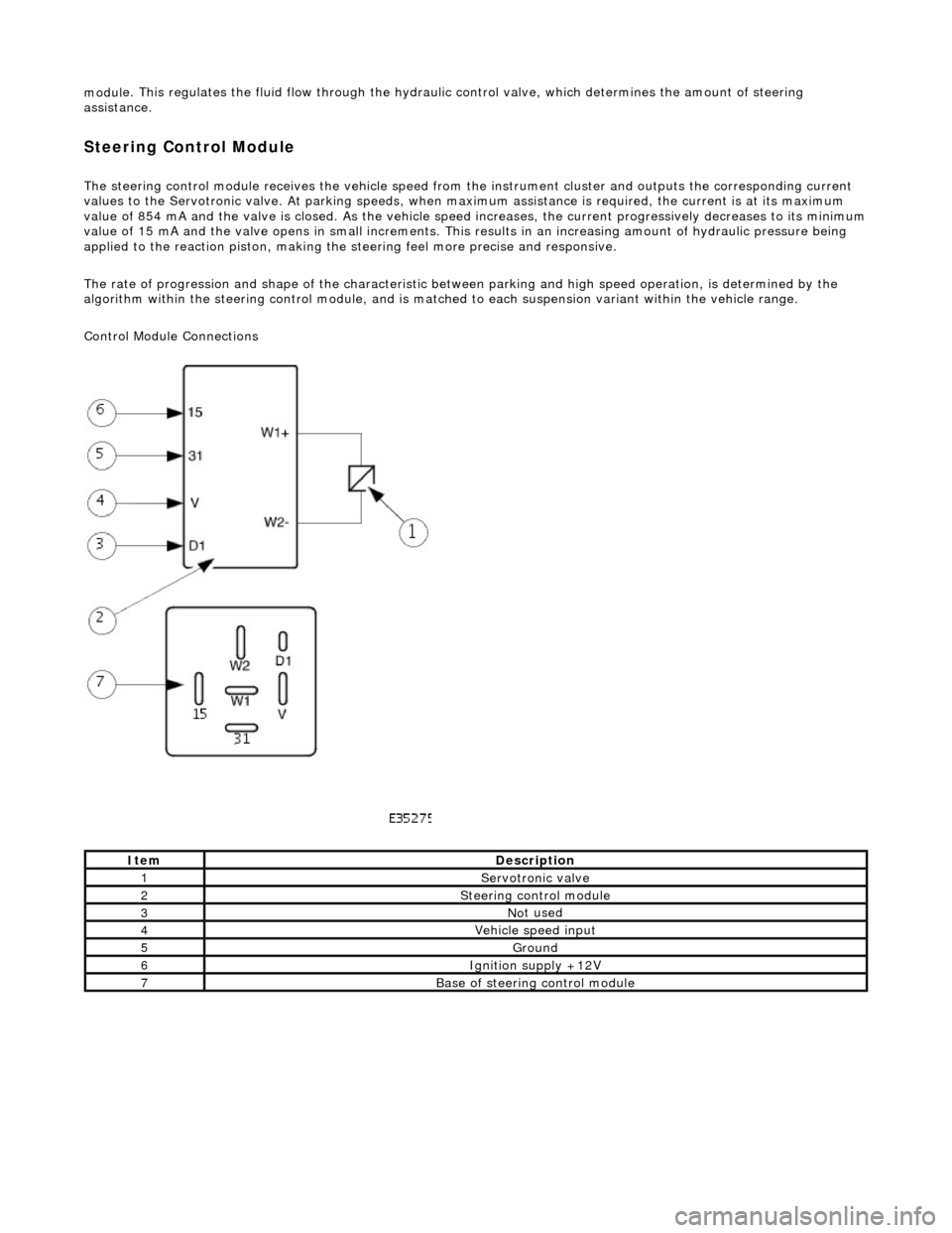
The steering control
module re
ceives the vehicle speed from the instrument cluster and outputs the corresponding current
values to the Servot ronic valve. At parking speeds, wh en maximum assistance is required , the current is at its maximum
value of 854 mA and the valve is closed. As the vehicle speed increases, the current progressively decreases to its minimum
value of 15 mA and the valve opens in sma ll increments. This results in an increasing amount of hydraulic pressure being
applied to the reaction piston, making the steering feel more precise and responsive.
The rate of progression and shape of the characteristic between parking and high speed operation, is determined by the
algorithm within the steering control module, and is matched to each suspension variant within the vehicle range.
Control Module Connections
It
em
De
scription
1Servotronic valve
2Steeri
ng control module
3No
t used
4Vehi
cle speed input
5Ground
6Ignition su
pply +12V
7Base of
steering control module
Page 508 of 2490
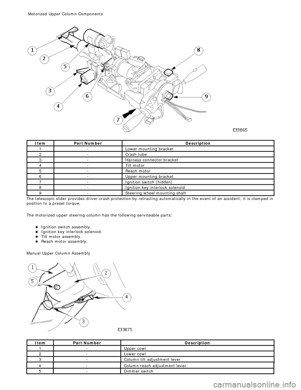
The te
lescopic slider provides driver crash
protection by retracting automatically in the event of an accident; it is clamped in
position to a preset torque.
The motorized upper steering column has the following serviceable parts:
Igniti
on switch assembly.
Igni
ti
on key interlock solenoid.
Ti
lt
motor assembly.
Reach motor assembly.
Manu al Upper Column Assembly
Ite
m
Par
t
Number
De
scr
iption
1-L
o
wer mounting bracket
2-Crash tube
3-Harnes
s c
onnector bracket
4-Tilt motor
5-Reach m
otor
6-Upper
moun
ting bracket
7-Ignition switc
h
(hidden)
8-Igni
ti
on key interlock solenoid
9-S
t
eering wheel mounting shaft
It
e
m
Par
t
Number
De
scr
iption
1-Upper
cowl
2-Lower cowl
3-Colu
mn tilt adjustment lever
4-Col
u
mn reach adjustment lever
5-Di
mm
er switch
Motorized Upper Co
lumn Components
Page 509 of 2490
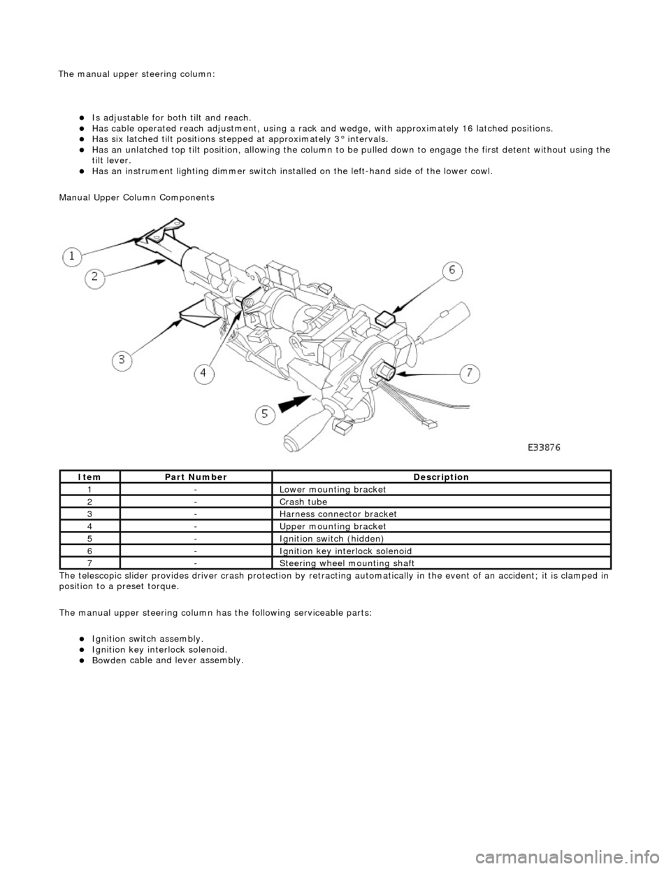
Is adjustable for both til
t and reach.
Has ca
ble operated reach adjustment, using a rack an
d wedge, with approximately 16 latched positions.
Has si
x latched tilt positions steppe
d at approximately 3° intervals.
Has an u
nlatched top tilt position, allowing the column to be
pulled down to engage the first detent without using the
tilt lever.
Has an instrument li
ghti
ng dimmer switch installed on the left-hand side of the lower cowl.
Manual Upper Column Components
The telescopic slider provides driver crash protection by retracting automatically in the event of an accident; it is clamped in
position to a preset torque.
The manual upper steering column has the following serviceable parts:
Igni
tion switch assembly.
Igni
tion key interlock solenoid.
Bowden
cable and lever assembly.
It
em
Par
t Number
De
scription
1-L
ower mounting bracket
2-Crash tube
3-Harnes
s connector bracket
4-Upper
mounting bracket
5-Ignition switc
h (hidden)
6-Igni
tion key interlock solenoid
7-S
teering wheel mounting shaft
The manu
al upper
steering column:
Page 515 of 2490
Steering Column Switches - Steering Column Switches
Description an
d Operation
Ig
nition Switch
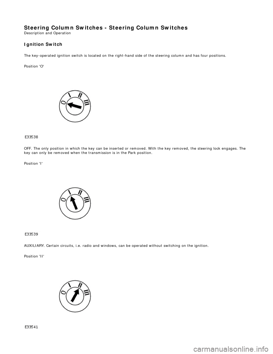
The k
ey-operated ignition switch is located on the right-hand side of the steering colu
mn and has four positions.
Position 'O'
OFF. The only position in which the key can be inserted or re moved. With the key removed, the steering lock engages. The
key can only be removed when the tran smission is in the Park position.
Position 'I'
AUXILIARY. Certain circuits , i.e. radio and windows, can be operat ed without switching on the ignition.
Position 'II'
Page 516 of 2490
IGNITION.
All circuits, except the star
ter motor, are activated. The key rema ins in this position when driving.
Position 'III'
START. The starter operates for as long as the key is held in this position, ag ainst spring pressure. If the engine fails to
start, the key must be returned to position 'I' befo re another start is attempted.
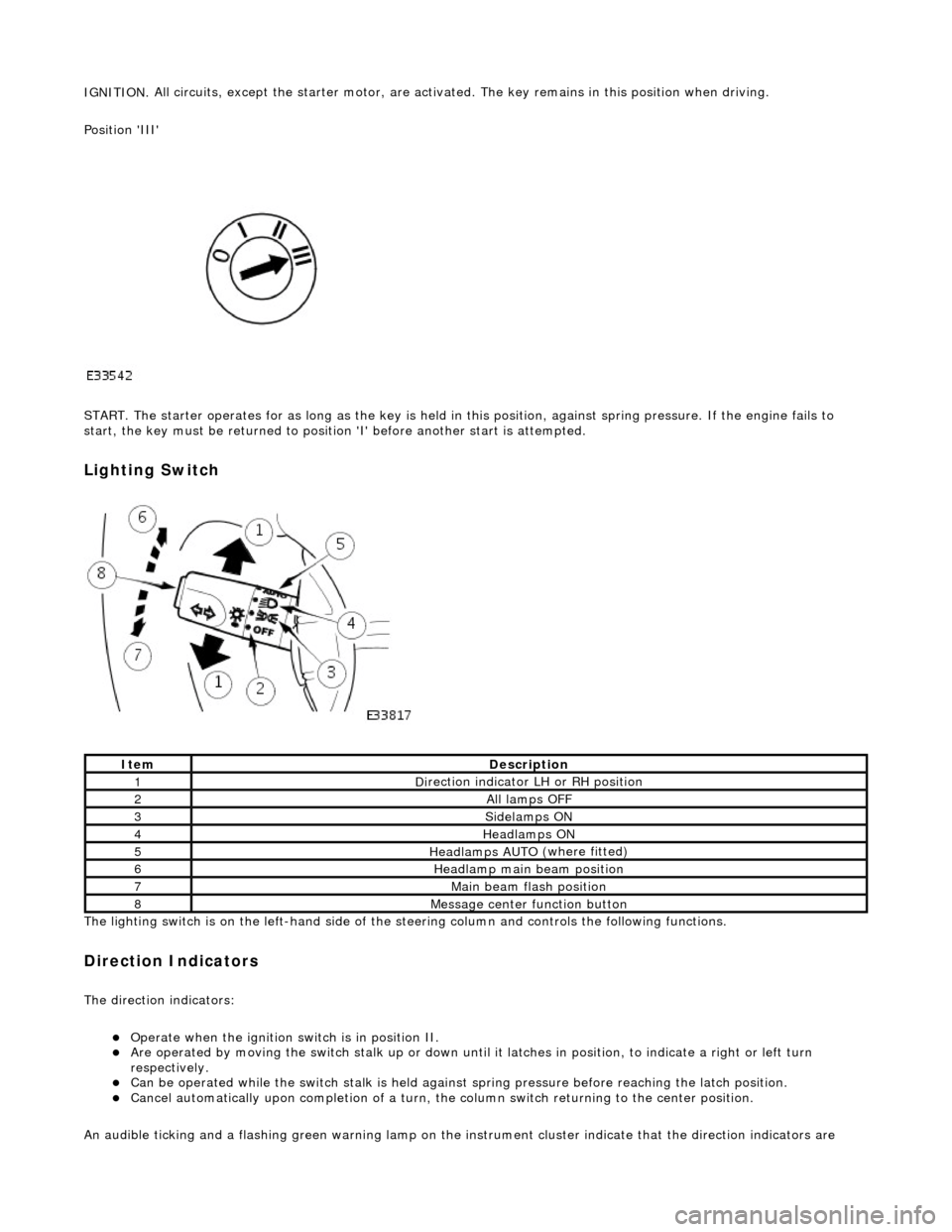
Lighting Switch
The li
ghting switch is on the left-h
and side of the steering column and controls the following functions.
Direction Indicators
The direction in
dicators:
Operate
when the ignition switch is in position II.
Are operat
ed by movi
ng the switch stalk up or down until it latches in position, to in
dicate a right or left turn
respectively.
Can be o p
erated while the switch stalk is held against
spring pressure before reaching the latch position.
Cancel
automatically upon completion of a turn, the
column switch returning to the center position.
An audible ticking and a flashing green warning lamp on the in strument cluster indicate that the direction indicators are
Ite
m
De
scr
iption
1D
i
rection indicator LH or RH position
2All lamps OFF
3Side
lamps ON
4Headlamps ON
5Headlamps AUT O
(where fitted)
6He
adlam
p main beam position
7Mai
n
beam flash position
8M
e
ssage center function button