panel JAGUAR X308 1998 2.G User Guide
[x] Cancel search | Manufacturer: JAGUAR, Model Year: 1998, Model line: X308, Model: JAGUAR X308 1998 2.GPages: 2490, PDF Size: 69.81 MB
Page 432 of 2490
It is a reciprocating two
-circuit pu
mp in which one brake circuit is as signed to each pump circuit.
It supplies th
e fluid pressure and vo
lume to supply the brake circuits under ABS and Traction control.
The pump is driven by an electri
c motor, with the pump
housing incorporating two lo w pressure accumulators and
damping chambers for each brake circuit.
The ac cu
mulator stores the pressure and smooths out the output pu
lses from the pump.
ABS Warning Lamp
The sys
tem will be set in a fail-safe mode if a problem is de
tected; a warning lamp on the instrument panel will notify the
driver there is a problem.
Anti-Lock Braking Sy
stem (ABS)
The AB
S components are combined with
an hydraulic booster and a tandem master cylinder to provide a two circuit braking
system. The system comprises, four wheel speed sensor s, a brake control modulator and an ABS warning lamp.
Should a wheel start to lock-up during braking a signal tr ansmitted from the wheel speed sensor to the brake control
modulator will start the hydraulic pump. The brake control modula tor will close the input valve of the line connected to the
locked-wheel to stop any increase in fluid pressure to the br ake caliper. If this fails to prevent the wheel locking, the
pressure in the caliper will be decreased by opening the return valve until th e wheel starts accelerating again. The fluid
pressure from the return va lve is directed into the low pressure accumulator, housed in the pump.
From the low pressure accumulator, fl uid is pumped through the damping cham ber to the brake master cylinder. The
pressure to the brake caliper will then be increased in small steps to maintain maximum adhesion between the tire and road
surface. This is achieved by closing the return valve, and opening the input valve and using the hydraulic pump to increase
the pressure.
Although the system senses all four wheels independently, the rear wheels are regulated as a pair. If a sensor on a rear
wheel detects a wheel decelerating rapidly, then the fluid pressure to both wheels is reduced. The fluid pressure is then
dictated by the wheel having the lowe st adhesion with the road surface.
The ABS system will be set in a fail-safe mode if a problem is detected; a warn ing lamp on the instrument panel will notify
the driver there is a problem. The brake system will still operate conventionally and with the same standard of performance
as a vehicle not equipped with ABS.
Automa tic Stability Control (ASC)
Th
e ASC utilizes the ABS sensing arrangement to provide the maximum traction force to propel the vehicle.
The ASC is switched on when the engine is started. The system can be switched off by pressing the 'ASC OFF' (the switched
is marked 'TRAC OFF' on vehicles fitted with traction control). The switch, which is situated in the center console switchpack,
lights up to warn that the system is sw itched off. An 'ASC' amber warning light flashes on the instrument panel when the
system detects a spinning wheel.
The ASC system uses engine intervention to reduce the torque delivered to the drive wheels to prevent them spinning.
Engine torque is re duced in three ways:
The
throttle is moved towards the closed position.
The ignition is retarded. F
u
el is cut-off at the cylinder injectors.
Wheel spin is detected by the wheel sp eed sensors and communicated to the AB S/TCCM. The ABS/TCCM uses information
from the controller area network (CAN) to calculate the torque that the engine should produce to stop the wheel spinning.
Torque reductions are then requested from the engine control module (ECM ) through the CAN. The throttle is then
positioned to provide the target torque, which has been calculated to prevent wheel spin. During the transient phase of
torque reduction the fuel is cut-off and th e ignition retarded Both the fuel cut-off an d ignition retard will be restored to
normal when the throttle is set to its new position.
The ASC uses a brake control modulator with six solenoid va lves: three normally open inlet valves and three normally
Page 433 of 2490
clos
ed outlet valves.
Traction Control
Trac
tion control has the same capabilities as ASC but with th
e added ability to actuate the brakes of the spinning wheel.
This enhances ASC by improving acceleration particularly on surfaces with uneven friction , e.g. one wheel on ice the other
on tarmac.
When wheelspin occurs, brake line pressure to the slipping wheel is generated, to operate that wheel's brake. The BCM
achieves this by closing the cut-off solenoid valve and oper ating the hydraulic pump. Brake fluid is then drawn from the
reservoir through the non-actuated mast er cylinder to the brake caliper.
A 'TRAC' amber warning light flashes on the instrument panel when the system detects a spinning wheel.
The traction control system uses a brake control modulator with nine solenoid valv es: four normally open inlet valves and
four normally closed outlet valves and one special isolating va lve. The outlet valves control the brakes of each each rear
wheel individually on the traction control system.
Rear Wheel Speed Senso
rs and ABS/TCCM Circuit Diagram
Page 505 of 2490
Steering Column - Steering Column
Description an
d Operation
Stee
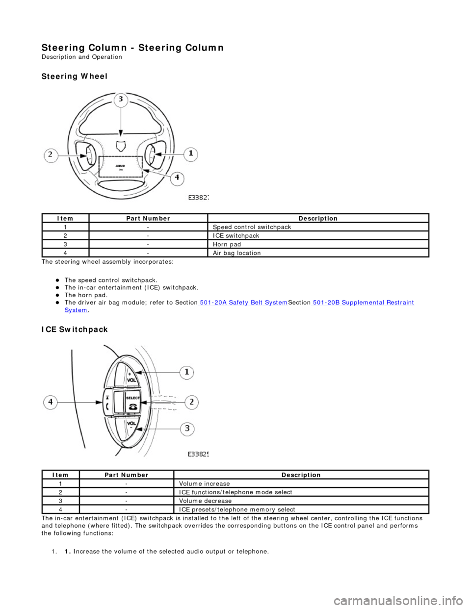
ring Wheel
T
he steering wheel assembly incorporates:
The s
peed control switchpack.
The i
n-car entertainment (ICE) switchpack.
The h
orn pad.
The driver ai
r bag module; refer to Section
501
-20A Safety Belt
System
Sectio
n
501
-2
0B Supplemental Restraint
Sy
stem
.
I
CE Switchpack
The
in-car entertainment (ICE) switchpack is installed to the le
ft of the steering wheel center, controlling the ICE functions
and telephone (where fitted). The switchpack overrides the corresponding bu ttons on the ICE control panel and performs
the following functions:
1. 1. Increase the volume of the select ed audio output or telephone.
It
em
Par
t Number
De
scription
1-Spe
ed control switchpack
2-I
CE switchpack
3-Horn pad
4-Air bag lo
cation
It
em
Par
t Number
De
scription
1-Vol
ume increase
2-ICE func
tions/teleph
one mode select
3-Volum
e decrease
4-ICE pres
ets/telephone memory select
Page 530 of 2490
Engi
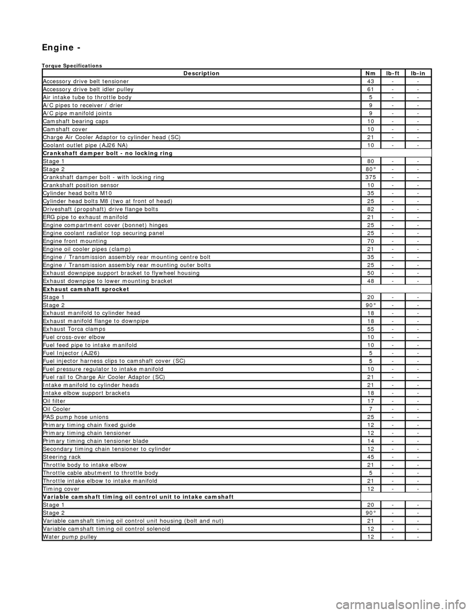
ne -
Torqu
e Specifications
De
s
cription
Nmlb
-
ft
lb
-
in
A
ccessory
drive belt tensioner
43--
A
ccessory
drive belt idler pulley
61--
Air in
ta
ke tube to throttle body
5--
A/C
pipes t
o receiver / drier
9--
A/C pipe m
anifold joints
9--
Camsh
aft bearin
g caps10--
Ca
msh
aft cove
r10--
Ch
arge Air Co
oler Adaptor to cylinder head (SC)
21--
Co
olan
t outlet pipe (AJ26 NA)
10--
Cran
kshaft damper bolt - no lockin
g ring
St
ag
e 1
80--
Stag
e 2
80°--
C
r
ankshaft damper bolt - with locking ring
37
5--
Cra
nkshaft position sensor
10--
Cy
li
nder head bolts M10
35--
Cy
lin
der head bolts M8 (two at front of head)
25--
Driv
es
haft (propshaft) drive flan
ge bo
l
ts
82--
ERG p
i
pe to exhaust manifold
21--
Engi
ne compartment cover (bonnet) hinges
25--
En
gine
coolant radiator top securing panel
25--
E
ng
ine front mounting
70--
En
gine
oil cooler pipes (clamp)
21--
En
gi
ne / Transmission assembly rear mounting centre bolt
35--
En
gi
ne / Transmission assembly rear mounting outer bolts
25--
Ex
ha
ust downpipe support bracket to flywheel housing
50--
Ex
ha
ust downpipe to lower mounting bracket
48--
E
x
haust camshaft sprocket
St
age 120--
Stage 290 °--
Ex
haust manifold to cylinder head
18--
Ex
ha
ust manifold flange to downpipe
18--
E
x
haust Torca clamps
55--
Fuel cross-over elbo
w
10--
Fu
el f
eed pipe to intake manifold
10--
Fuel
Injector (AJ
26)
5--
Fuel
injector ha
rness clips to camshaft cover (SC)
5--
Fu
el p
ressure re
gu
l
ator to intake manifold
10--
F
u
el rail to Char
ge
A
ir Cooler Adaptor (SC)
21--
In
ta
ke manifold to cylinder heads
21--
Inta
ke elbow support brackets
18--
Oil f
i
lter
17--
Oil C
o
oler
7--
P
AS pu
mp hose unions
25--
P
r
imary timing chain fixed guide
12--
P
r
imary timing chain tensioner
12--
Pr
imary timing chain tensioner blade
14--
S
e
condary timing chain tensioner to cylinder
12--
S
t
eerin
g ra
ck45--
Thro
ttle body to intake elbow
21--
Th
ro
ttle cable abutment to throttle body
5--
Th
ro
ttle intake elbow to intake manifold
21--
Ti
mi
ng cover
12--
Variable camshaft t
i
ming oil control unit to intake camshaft
St
ag
e 1
20--
St
ag
e 2
90
°--
Var
iable camshaft timing oil control unit housing (bolt and nut)
21--
Va
ria
ble camshaft timi
ng oil control solenoid
12--
Wa
ter pump pulley
12--
Page 899 of 2490

16. Disconnect the air cleaner cover.
Remove the five clips which se cure the air cleaner cover.
17. Remove the intake tube / air flow meter / air cleaner cover
assembly.
1. Remove the intake tube / air flow meter / air cleaner
cover assembly.
2. Remove and discard the ru bber seal; air intake tube
to throttle body.
18. Remove the centre trim panel from the engine compartment.
1. Remove the left hand side enclosure panel.
2. Remove the centre trim panel.
19. Release the hoses (Quick Fit connections) from the expansion
tank, using 303 - 623.
1. Release the hose, expansion tank to thermostat housing (coolant outlet pipe on supercharged
engines).
Page 901 of 2490
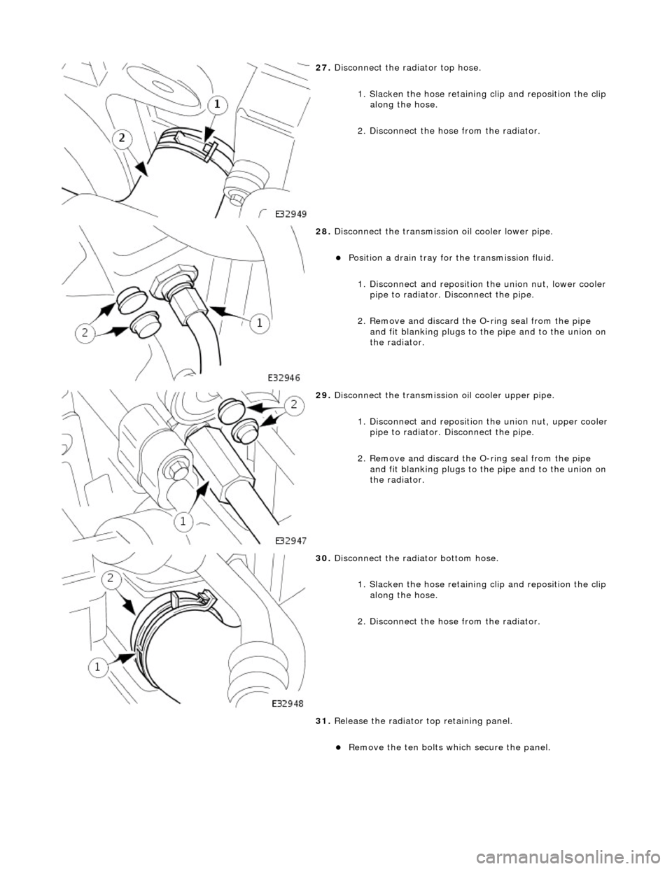
27. Disconnect the radiator top hose.
1. Slacken the hose retaining clip and reposition the clip
along the hose.
2. Disconnect the hose from the radiator.
28. Disconnect the transmission oil cooler lower pipe.
Position a drain tray for the transmission fluid.
1. Disconnect and reposition the union nut, lower cooler pipe to radiator. Di sconnect the pipe.
2. Remove and discard the O- ring seal from the pipe
and fit blanking plugs to the pipe and to the union on
the radiator.
29. Disconnect the transmission oil cooler upper pipe.
1. Disconnect and reposition the union nut, upper cooler pipe to radiator. Di sconnect the pipe.
2. Remove and discard the O- ring seal from the pipe
and fit blanking plugs to the pipe and to the union on
the radiator.
30. Disconnect the radiator bottom hose.
1. Slacken the hose retaining clip and reposition the clip
along the hose.
2. Disconnect the hose from the radiator.
31. Release the radiator top retaining panel.
Remove the ten bolts which secure the panel.
Page 902 of 2490
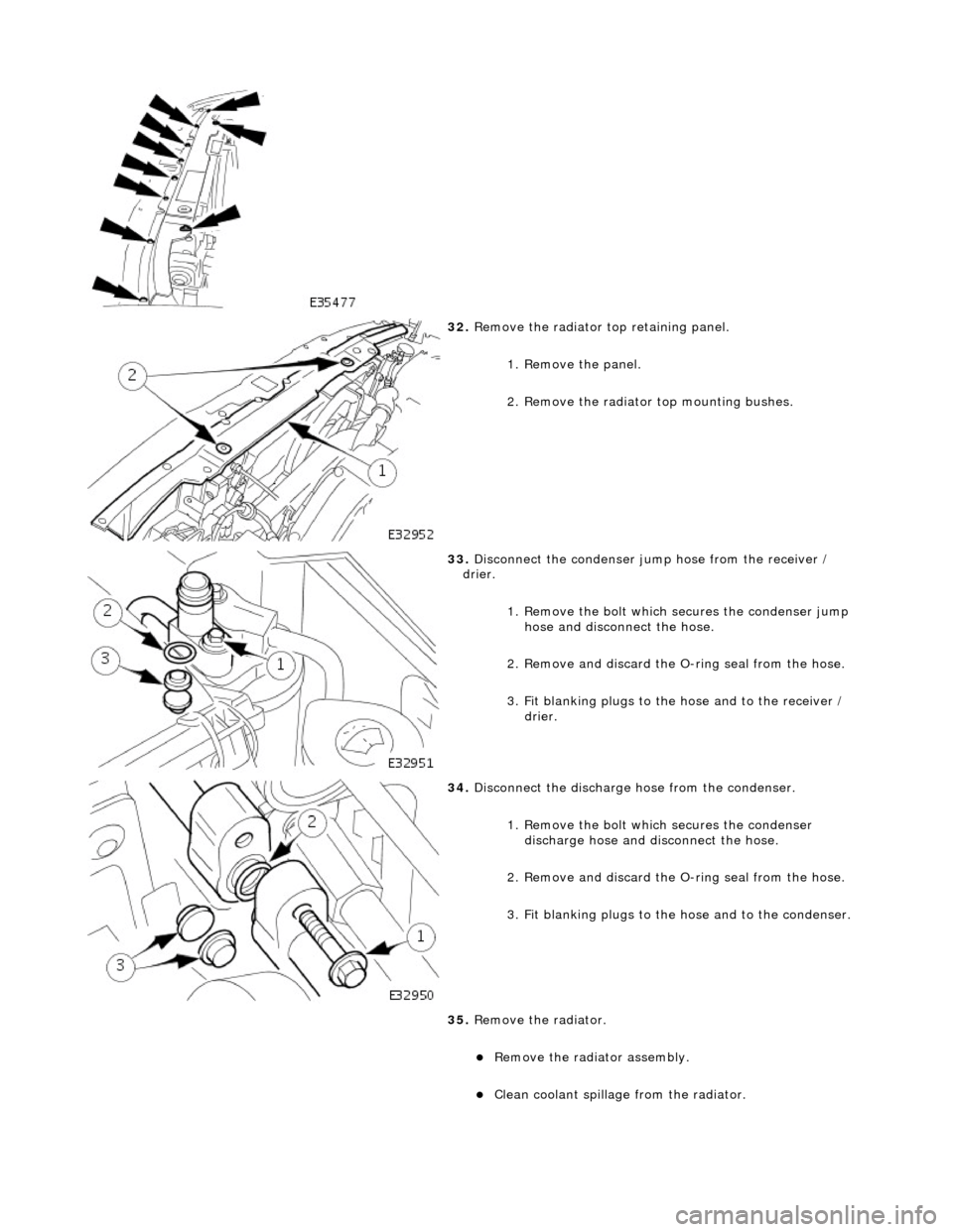
32. Remove the radiator top retaining panel.
1. Remove the panel.
2. Remove the radiator top mounting bushes.
33. Disconnect the condenser jump hose from the receiver /
drier.
1. Remove the bolt which secures the condenser jump hose and discon nect the hose.
2. Remove and discard the O-ring seal from the hose.
3. Fit blanking plugs to the hose and to the receiver / drier.
34. Disconnect the discharge hose from the condenser.
1. Remove the bolt which secures the condenser discharge hose and disconnect the hose.
2. Remove and discard the O-ring seal from the hose.
3. Fit blanking plugs to the hose and to the condenser.
35. Remove the radiator.
Remove the radiator assembly.
Clean coolant spillage from the radiator.
Page 918 of 2490
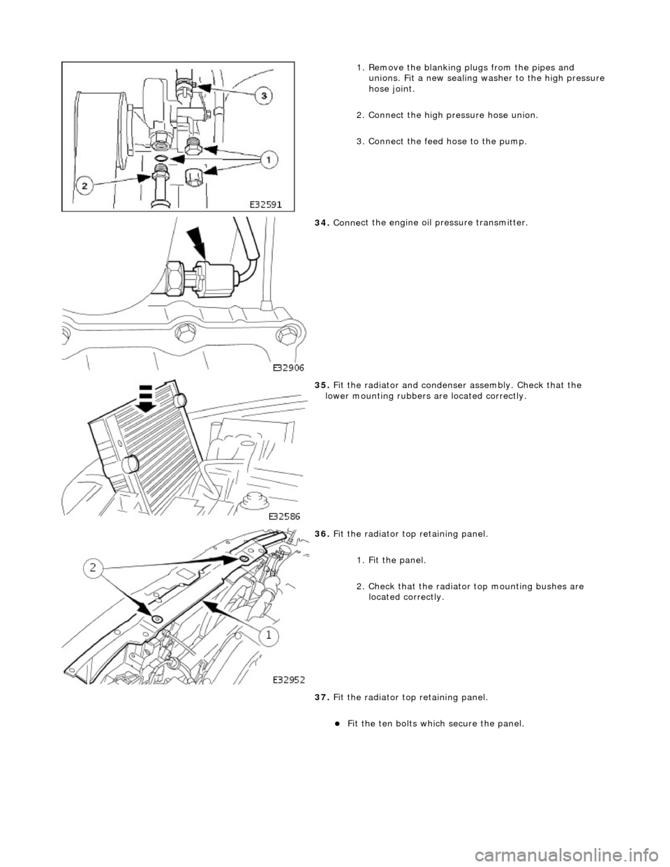
1.
Remove the blanking plugs from the pipes and
unions. Fit a new sealing washer to the high pressure
hose joint.
2. Connect the high pressure hose union.
3. Connect the feed hose to the pump.
34 . Conne
ct the engine oil
pressure transmitter.
35 .
Fit the radiator and
condense
r assembly. Check that the
lower mounting rubbers are located correctly.
36 . Fit the radiator top
retaining panel.
1. Fit the panel.
2. Check that the radiator top mounting bushes are
located correctly.
37. Fit the radiator top retaining panel.
Fit
the ten bolts which secure the panel.
Page 921 of 2490
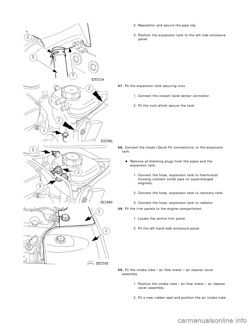
2
. Reposition and secure the pipe clip.
3. Position the expansion tank to the left side enclosure
panel.
47
.
Fit the expansion tank securing nuts.
1. Connect the coolant level sensor connector.
2. Fit the nuts which secure the tank.
48
.
Connect the hoses (Quick Fit connections) to the expansion
tank.
Remove all blanking plug s
from the pipes and the
expansion tank.
1. Connect the hose, expansion tank to thermostat housing (coolant outlet pipe on supercharged
engines).
2. Connect the hose, expansion tank to recovery tank.
3. Connect the hose, expansion tank to radiator.
49
.
Fit the trim panels to the engine compartment.
1. Locate the centre trim panel.
2. Fit the left hand side enclosure panel.
50. Fit the intake tube / air flow meter / air cleaner cover
assembly.
1. Position the intake tube / air flow meter / air cleaner
cover assembly.
2. Fit a new rubber seal and po sition the air intake tube
Page 929 of 2490

The cooling
pack incorporates the radiator a
ssembly with integral transmission oil cool er (located in the radiator outlet tank),
an air conditioning condenser, and the cooling fans and cowl assembly.
The cooling pack on supercharged vehicles is the same as described above, but with the addition of a charge air cooler
coolant radiator located in front of the condenser.
Radiator Mounti
ng/Retention
T
he radiator is mounted on four rubber mounts, one on each
end of the upper and lower horizontal face. The two lower
mountings are supported on two isolated brackets mounted on the body; the lower cradle assembly has subsequently been
deleted.
A closing panel made from polypropylene, which retains the radiat or assembly, fits over the top of the radiator and is bolted
to the vehicle top panel.
Coolant Hoses - Engine