panel JAGUAR X308 1998 2.G Repair Manual
[x] Cancel search | Manufacturer: JAGUAR, Model Year: 1998, Model line: X308, Model: JAGUAR X308 1998 2.GPages: 2490, PDF Size: 69.81 MB
Page 1645 of 2490

6. Connec
t the oxygen sensor multiplugs.
Con
nect the plug(s) to the respective (previously noted)
sensor(s).
Cor
rectly position the multiplu
gs on the mounting bracket.
7. F
it the coolant header tank.
1. Reposition the tank and fit the securing nuts.
2. Connect the harness connector
8. R
efit the centre trim panel and th
e left hand enclosure panel to
the engine compartment.
1. Refit the centre trim panel.
2. Refit the left hand enclosure panel.
9. Raise the vehicle on the ramp.
10. Tighten the mounting brac ket securing bolts.
Page 1654 of 2490

Exha
ust System - Catalyti
c Converter Gasket LH4. 0L NA V8 - AJ27/3.2L
NA V8 - AJ26
Re mo
val and Installation
Remova
l
1.
Op
en the engine compartment and fit paintwork protection
sheets.
2. Remove the front muffler; refer to Operation 30.10.18 in this
section.
3. Re
move the centre trim panel
from the engine compartment.
1. Remove the left hand side enclosure panel.
2. Remove the centre trim panel.
4. Repo
sition the expansion tank from the mounting.
1. Disconnect the coolant level sensor connector.
2. Remove the nuts which secures the tank.
5. CAUT
ION: Note the position of the upstream and
downstream (where fitted) o xygen sensor multiplugs for
reassembly.
Disconnect the oxygen sensor multiplugs.
Re
lease the multiplugs from th
e engine mounting bracket.
Dis
connect the plug(s) from the oxygen sensor(s)
6.
Re
move the four nuts which se
cure the downpipe catalytic
converter to the exhaust manifold.
Page 1656 of 2490

5. Connec t
the oxygen sensor multiplugs.
Con
n
ect the plug(s) to the respective (previously noted)
sensor(s).
Cor r
ectly position the multiplu
gs on the mounting bracket.
6. Fi
t the coolant header tank.
1. Reposition the tank and fit the securing nuts.
2. Connect the harness connector
7. Re
fit the centre trim panel and th
e left hand enclosure panel to
the engine compartment.
1. Refit the centre trim panel.
2. Refit the left hand enclosure panel.
8. Raise the ramp.
9. Tighten the mounting brac ket securing bolts.
Page 1658 of 2490

Exha
ust System - Cataly
tic Converter Gasket LH 4.0L SC V8 - AJ26
Remo
val and Installation
Remov
a
l
1.
Op
en the engine compartment and fit paintwork protection
sheets.
2. Re
move the centre trim panel
from the engine compartment.
1. Remove the left hand side enclosure panel.
2. Remove the centre trim panel.
3. Repo
sition the expansion tank from the mounting.
1. Disconnect the coolant level sensor connector.
2. Remove the nuts which secures the tank.
4. CAUT
ION: Note the position of the upstream and
downstream (where fitted) o xygen sensor multiplugs for
reassembly.
Disconnect the oxygen sensor multiplugs.
Di spl
ace the multiplugs from the engine mounting bracket.
Dis
connect the plug(s) from the oxygen sensor(s).
5.
Re
move the four nuts which se
cure the downpipe catalytic
converter to the exhaust manifold.
Page 1660 of 2490

In
stallation
1.
Fit a ne
w gasket to the mani
fold mating flange on the
downpipe.
2. Fit
the downpipe catalytic converter.
1. Fit the downpipe assembly to the manifold.
Fit,
but do not fully tighten, the mounting bracket securing
bolts. (Leave loose until the nu ts securing the downpipe to
the exhaust manifold are fitted.)
3. Lower the ramp.
4. Tigh te
n the nuts securing the downpipe flange to the manifold
flange.
5. Connec t
the oxygen sensor multiplugs.
Con
n
ect the plug(s) to the respective (previously noted)
sensor(s).
Cor r
ectly position the multiplu
gs on the mounting bracket.
6. Fi
t the coolant header tank.
1. Reposition the tank and fit the securing nuts.
2. Connect the harness connector
7. Refit the centre trim panel and th e left hand enclosure panel to
the engine compartment.
Page 1661 of 2490

1
. Refit the centre trim panel.
2. Refit the left hand enclosure panel.
8. Raise the vehicle on the ramp.
9. Tigh
ten the mounting brac
ket securing bolts.
10
.
Connect the downpipe cataly tic converter to the front
muffler.
1. Position a new gasket to the flange studs at each side.
2. Connect the the front mu ffler assembly to each
downpipe.
3. Fit and tighten the nuts to secure the muffler to the downpipes.
11
.
Fit the front muffler rear mounting.
1. Reposition the front mu ffler and align the rear
mounting.
2. Fit and tighten the bolts; muffler to mounting bracket.
12. Lower the ramp.
13. Remove the paintwork protection sheets and close the engine
cover.
Page 1693 of 2490

Filler Cap and P
ipe
The fuel
filler cap with bayonet-type fixi
ng is located beneath a remote-release sp ring-latched lid on the rear saddle panel
on the left-hand-side of the vehicle.
Fuel Pum
p
The fu
el pump(s) is energized by an ECM co
ntrolled relay. Fuel is drawn by this pu mp and supplied to the fuel injectors via
the fuel line, filter and fuel rails.
Servicing of the fuel pump re quires fuel tank removal.
Ev
aporative Loss Flange Assembly
The evaporative-loss flan
ge asse
mbly is mounted centrally on top of the tank. The flange assembly consists of a removeable
steel cap which mounts the evaporative emissions system vapor outlet valves and, if applicable, a pressure sensor. The
external electrical supply to th e fuel pump(s) is also made via a connector on the flange.
The flange assembly is fixed to the tank by a locking ring which is turned usin g special tool JD-174. A seal is fitted between
the flange assembly and the tank. Three di fferent flange assemblies are applicable according to the evaporative emission
system fitted to the vehicle. The fl ange size and fixing are identical fo r the three systems, as described.
Removal of the evaporative flange assembly is necessary to gain access to th e fuel pump(s) and other internal components.
To remove the evaporative fl ange assembly the fuel tank must first be removed.
The evaporative flange variant assemblies are described, together with service information, in Section 303-13.
Fuel R
eturn
Excess fuel
is directed back to
the fuel tank via a return line.
Fuel Pum
p Relay
The
fuel pump relay,
under control of the ECM, switches power to the fuel pump motor.
I
nertia Fuel Shutoff (IFS) Switch
The IF
S switch is located in the right-hand
side footwell behind the footboard carpet . When activated the switch isolates the
ignition system and fuel pump, releases any locked doors and disables unnecessary electrical systems. The system can be
reset by pressing down the flexible cover on the top of the switch.
• NOTE: The doors will not unlock if the IFS switch is tripped when the ignition switch is in position '0'.
Page 1758 of 2490

Climate Control System - General Informatio
n - Climate Control System
D
iagn
osis and Testing
I
n
troduction
It is very i
m
portant to positive
ly identify the area of concern before starting a rectification procedure. A little time spent with
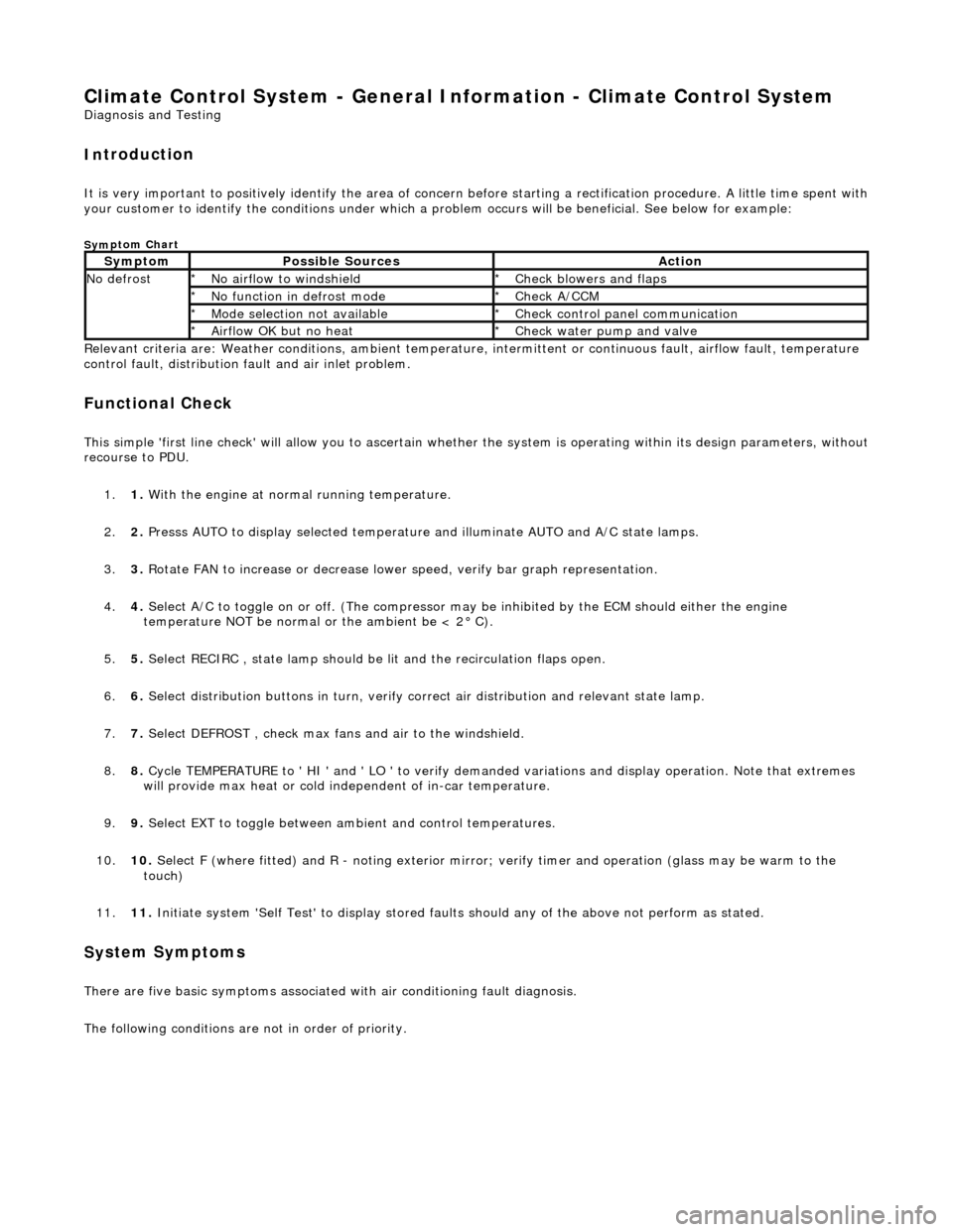
your customer to identify the conditions under which a pr oblem occurs will be beneficial. See below for example:
Sym
ptom Chart
Re
lev
ant criteria are: Weather conditions,
ambient temperature, intermittent or cont inuous fault, airflow fault, temperature
control fault, distribution fault and air inlet problem.
Functio n
al Check
This
s
imple 'first line check' will allo
w you to ascertain whether the system is operating within its design parameters, withou t
recourse to PDU.
1. 1. With the engine at normal running temperature.
2. 2. Presss AUTO to display selected temperature and illuminate AUTO and A/C state lamps.
3. 3. Rotate FAN to increase or decrease lowe r speed, verify bar graph representation.
4. 4. Select A/C to toggle on or off. (T he compressor may be inhibited by the ECM should either the engine
temperature NOT be normal or the ambient be < 2° C).
5. 5. Select RECIRC , state lamp should be lit and the recirculation flaps open.
6. 6. Select distribution butt ons in turn, verify correct air distribution and relevant state lamp.
7. 7. Select DEFROST , check max fans and air to the windshield.
8. 8. Cycle TEMPERATURE to ' HI ' and ' LO ' to verify demanded variations and display operation. Note that extremes
will provide max heat or cold independent of in-car temperature.
9. 9. Select EXT to toggle between am bient and control temperatures.
10. 10. Select F (where fitted) and R - noting exterior mirror; verify timer and operation (glass may be warm to the
touch)
11. 11. Initiate system 'Self Test' to display stored faul ts should any of the above not perform as stated.
Sy
stem Symptoms
There
are five
basic symptoms associated
with air conditioning fault diagnosis.
The following conditions are not in order of priority.
Sy m
ptom
Possib
l
e Sources
Acti
o
n
N
o defrostN o
airflow to windshield
*
Check blower s and flaps
*
N o functi
on in defrost mode
*
Check A/CCM
*
Mo de s
election not available
*
Chec k
control panel communication
*
Ai rfl
ow OK but no heat
*
Check water pu
mp and valve
*
Page 1769 of 2490

Air Distribution and Filtering - Air Distri
bution and Filtering
Description an
d Operation
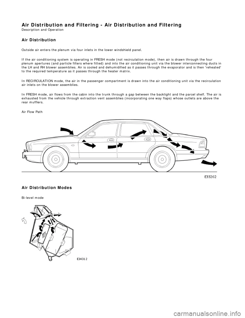
Air Distribution
Ou
tside air enters the plen
um via four inlets in the lower windshield panel.
If the air conditioning system is operating in FRESH mode (not recirculation mode), then air is drawn through the four
plenum apertures (and particle filters where fitted) and into the air conditioni ng unit via the blower interconnecting ducts in
the LH and RH blower assemblies. Air is c ooled and dehumidified as it passes through the evaporator and is then 'reheated'
to the required temperature as it passes through the heater matrix.
In RECIRCULATION mode, the air in the pass enger compartment is drawn into the air conditioning unit via the recirculation
air inlets on the blower assemblies.
In FRESH mode, air flows from the cabin into the trunk through a gap between the backlight and the parcel shelf. The air is
exhausted from the vehicle through extraction vent assemblies (incorporating one way flaps) whose outlets are above the
rear mufflers.
Air Flow Path
Air Distribution Modes
Bi
-level mode
Page 1773 of 2490

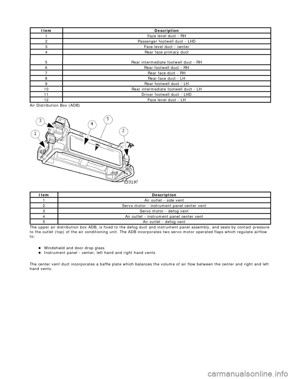
Ai
r Distribution Box (ADB)
The upper air distribution box ADB, is fixed to the defog duct and instrument panel assembly, and seals by contact pressure
to the outlet (top) of the air conditioning unit. The ADB inco rporates two servo motor operated flaps which regulate airflow
to:
Windshield and door drop
glass
Instrument panel
- center, left
hand and right hand vents
The center vent duct incorporat es a baffle plate which balances the volume of air flow between the center and right and left
hand vents.
5R
ear intermediate footwell duct - RH
6R
ear footwell duct - RH
7R
ear face duct - RH
8R
ear face duct - LH
9R
ear footwell duct - LH
10R
ear intermediate footwell duct - LH
11D
river footwell duct - LHD
12Fac
e level duct -
LH
It
em
De
scription
1Ai
r outlet - side vent
2Servo motor -
instrume
nt panel center vent
3Servo motor -
defog vent
4Ai
r outlet - instrume
nt panel center vent
5Ai
r outlet - defog vent
It
em
De
scription
1Fac
e level duct - RH
2Passenger footwel
l duct - LHD
3Fac
e level duct - center
4Rear
face primary duct