panel JAGUAR X308 1998 2.G Owner's Guide
[x] Cancel search | Manufacturer: JAGUAR, Model Year: 1998, Model line: X308, Model: JAGUAR X308 1998 2.GPages: 2490, PDF Size: 69.81 MB
Page 1269 of 2490

2.2. Check on non-volatile diagnostic memory by wr iting a test pattern and then reading it back.
3. 3. Internal 'watchdog' hardware to check whether the TCM has crashed.
Transmission Control Module Supply Voltage
The TCM monitors battery and igni tion switched supply voltages.
A permanent supply is used to maintain a battery backed 'memor y'. Should this supply be cut, due to battery disconnection
perhaps, the 'adaptive shift' valu es will be lost. This will result in a small reduction in shift quality for a period until th e
adaptions are 're-learned'
The TCM will adopt 'limp home' mode as a result of the supply voltage being >16V or <7V with an engine speed >1600
rpm.
Should the ignition supply be >7V but <9V the TCM will hold the gear that it has currently selected. If after 2.5 seconds,
with the engine speed >1600 rpm, the voltage remains at this level, 'limp home' mode will be adopted. The 2.5 second
delay is built in to prevent reaction to a momentary voltage fluctuation.
Operation
CAUTION: Disconnection of the TCM and / or the vehicle batt ery will cause system adaptions to be lost; this may be
apparent by shift quality degradation. Fo llowing reconnection, a period of 'varied' driving will reinstate adaptions and thus
normal operation. Please ensure that the customer is made aware that the adaption period is variable and may occur after
handover, as the transmission re-learns the prevailing driving style.
• NOTE: Should the TCM fail, please ensure that the control housing cooling fan is operating correctly. Failure of the cooling
fan MUST be rectified before renewing the TCM and details of a fan fa ilure should accompany the returned TCM.
The TCM processes information received in both analogue and digital form, such as:
Transmission input speed Transmission output speed Throttle position Pedal demand Gear selector position Engine torque Engine speed Transmission oil temperature Mode switch
This information is then used by the TC M to control shift energy management and decide which shift program to implement
and which gear to select.
The TCM uses the various sensors and inpu ts to monitor the correct operation of the system an d is programmed to take
default action and inform the operator when a fault occurs.
Safety Functions
The safety functions are designed to safeguard against inappr opriate actions by the operator as well as against system
malfunctions. The system prevents reve rse gear from being engaged at high forward speeds and prevents manual
downshifting at excessive engine speeds; these functions are not operational in mechanical limp-home mode.
The TCM constantly monitors the transmissi on for faults. In the event of a problem the TCM will adopt a 'limp home' mode
in which only P R N D - (selector in D but only fourth gear is enabled) are available. The operator will be made aware of
certain faults by an in strument panel warning.
The electrical and diagnostic system has been designed such that system integrity is protected at all times, the safety
concept being based on th e following three points:
Page 1357 of 2490

Automatic Transmission/Transaxle - 4.0L NA V8 - AJ27/3.2L NA V8 - AJ26
- Transmission Control Module (TCM)
In-vehicle Repair
Removal
1. Disconnect battery ground cable.
Remove the battery cover.
2. Remove the trim panel from the engine compartment,
passenger side.
1. Remove the left hand side enclosure panel.
2. If necessary, remove the centre trim panel.
3. Release the fixings and remove the cover from the ECM / TCM
housing.
4. Disconnect the TCM harness multiplug EM007.
5. Lift the TCM from its housing.
Page 1449 of 2490

8. Remove the centre trim panel from the engine compartment.
1. Remove the left hand side enclosure panel.
2. Remove the centre trim panel.
9. Move the coolant header tank for access.
1. Disconnect the bleed pipe, header tank to radiator .
2. Remove the header tank fixings.
10. Fit engine lifting bracket 307 - 536 at the rear LH.
11. Support the engine using 307 - 021.
1. Adjust and locate the side support brackets to fit into
the LH and RH body channels and tighten the beam
fixings.
2. Engage the support hooks in to the engine rear lifting
Page 1478 of 2490

Automatic Transmission/Transaxle External Controls - 4.0L NA V8 -
AJ27/3.2L NA V8 - AJ26 - Brake Shift Interlock Actuator Adjustment
General Procedures
1. Disconnect battery ground cable.
Remove the battery cover.
2. Remove the J-gate surround, Section 501-05.
3. Remove the console finisher ve neer panel, Section 501-12.
4. Remove the interlock soleno id actuating lever cover.
5. Move the shift lever to N.
Operate the gearshift interlock latch manually to release
the selector lever from P .
6. NOTE: Assistance from anot her person is required.
Adjust the gearshift interlock solenoid. 1. Slacken the solenoid fixings.
2. Hold the selector lever midway between P and R .
3. Move the solenoid rearwards, against spring pressure, to take up the free play.
4. Tighten the soleno id securing nuts.
5. Ensure that the interloc k actuating lever has no free
play with the selector lever midway between P and
Page 1482 of 2490

Automatic Transmission/Transaxle External Controls - 4.0L NA V8 -
AJ27/3.2L NA V8 - AJ 26 - Selector Lever Cable Adjustment
General Procedures
1. Disconnect battery ground cable.
Remove the battery cover.
2. Position the shift to N.
3. Remove the J-gate surround, Section 501-05.
4. Remove the console finisher ve neer panel, Section 501-12.
5. Remove the center console assembly, Section 501-12.
6. Slacken the selector cable locking nuts away from the
abutment.
7. Raise the vehicle for access.
8. Verify the transmission selector position ( N )
1. At the transmission, detach the inner cable from the selector lever.
2. With the lever moved fully rearward, push the lever forward two detents to achieve N.
3. Reconnect the inner cable.
9. From inside the vehicle.
10. NOTE: When setting the selector cable, ensure that the
transmission selector does not move from the N position.
Adjust the selector cable. 1. Position the shift in the N detent
2. Adjust the nuts to lock against the bracket without
Page 1484 of 2490

Automatic Transmission/Transaxle External Controls - 4.0L NA V8 -
AJ27/3.2L NA V8 - AJ26 - Br ake Shift Interlock Actuator
Removal and Installation
Removal
Installation
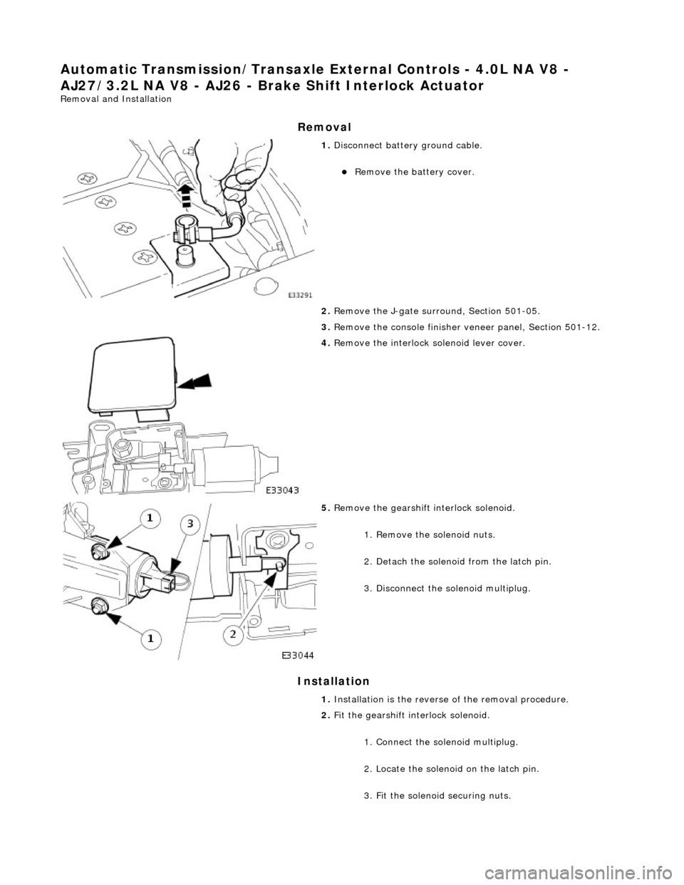
1. Disconnect battery ground cable.
Remove the battery cover.
2. Remove the J-gate surround, Section 501-05.
3. Remove the console finisher ve neer panel, Section 501-12.
4. Remove the interlock so lenoid lever cover.
5. Remove the gearshift interlock solenoid.
1. Remove the solenoid nuts.
2. Detach the solenoid from the latch pin.
3. Disconnect the solenoid multiplug.
1. Installation is th e reverse of the re moval procedure.
2. Fit the gearshift interlock solenoid.
1. Connect the solenoid multiplug.
2. Locate the solenoid on the latch pin.
3. Fit the solenoid securing nuts.
Page 1487 of 2490

Automatic Transmission/Transaxle External Controls - 4.0L NA V8 -
AJ27/3.2L NA V8 - AJ 26 - Selector Lever Cable and Bracket
Removal and Installation
Removal
1. Position the selector to N.
2. Remove the J-gate surround, Section 501-05.
3. Remove the console finisher ve neer panel, Section 501-12.
4. Remove the center console assembly, Section 501-12.
5. Raise the vehicle for access.
6. Detach the selector cable from the transmission unit.
1. Remove the cable inner to selector lever nut.
2. Remove the cable to transmission casing fixings.
7. Reposition the selector cable.
8. Remove the LH front seat, Section 501-10.
9. Reposition the LH floo r carpet for access.
10. Remove the selector cable to tunnel clip tie strap.
11. Detach the selector cable from the gear shift assembly.
1. Remove the inner cable to shift lever nut.
2. Slacken the outer cable locknuts.
Page 1490 of 2490

Automatic Transmission/Transaxle External Controls - 4.0L NA V8 -
AJ27/3.2L NA V8 - AJ 26 - Selector Lever Gate Finish Panel
Removal and Installation
Removal
Installation
1.
Apply protective tape to veneer along each side of 'J' gate
finisher.
2. Using a screwdriver in the slot in front of the finisher,
carefully lift the finisher an d ease it from the 'J' gate
surround.
1. Position finisher over gear selector.
2. Firmly seat finisher on veneer panel.
3. Remove protective tape from ve neer panel and using a suitable
cleaner, remove any residual adhesive.
Page 1491 of 2490

Automatic Transmission/Transaxle External Controls - 4.0L NA V8 -
AJ27/3.2L NA V8 - AJ 26 - Selector Lever Indicator Assembly
Removal and Installation
Removal
Installation
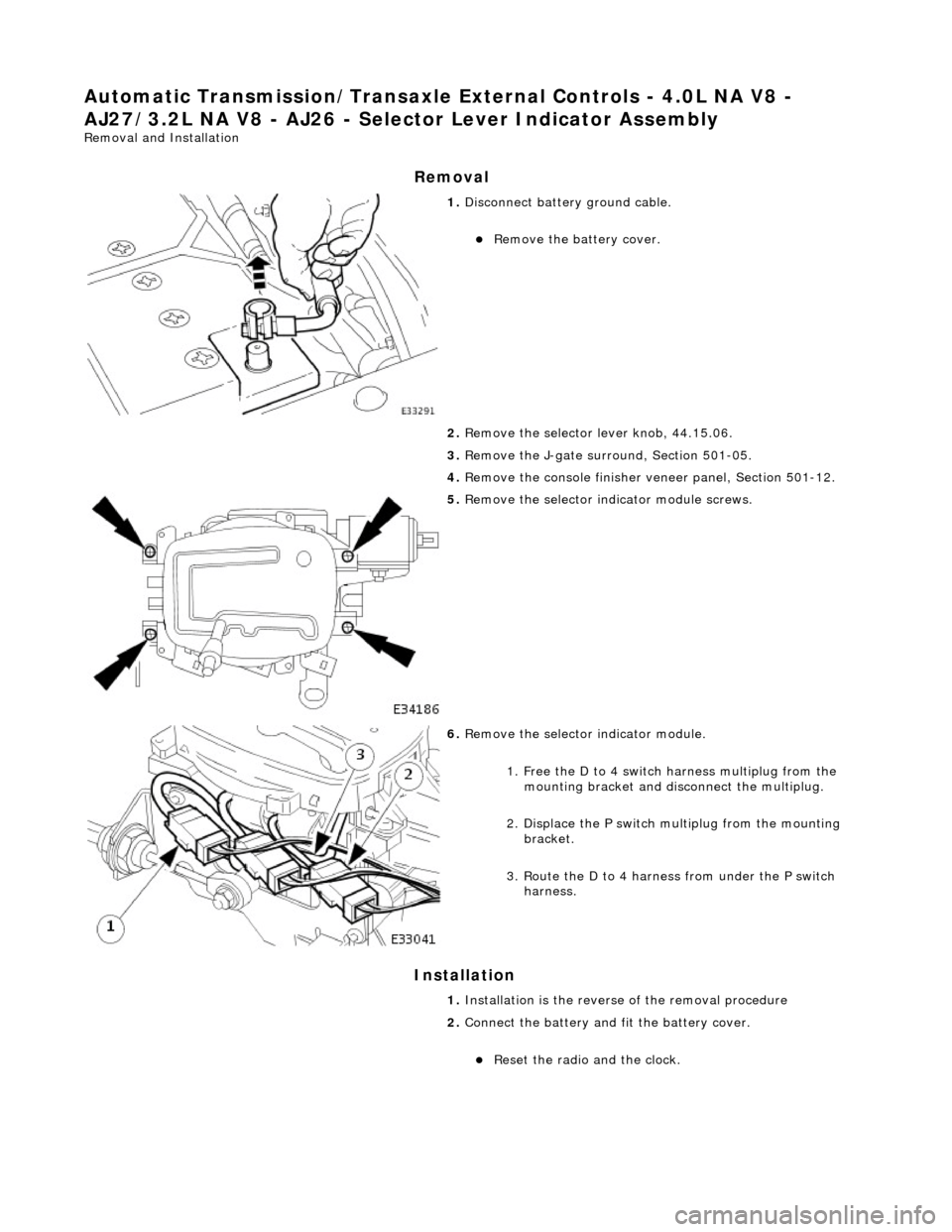
1. Disconnect battery ground cable.
Remove the battery cover.
2. Remove the selector lever knob, 44.15.06.
3. Remove the J-gate surround, Section 501-05.
4. Remove the console finisher ve neer panel, Section 501-12.
5. Remove the selector indicator module screws.
6. Remove the selector indicator module.
1. Free the D to 4 switch harness multiplug from the mounting bracket and disc onnect the multiplug.
2. Displace the P switch multiplug from the mounting bracket.
3. Route the D to 4 harnes s from under the P switch
harness.
1. Installation is the revers e of the removal procedure
2. Connect the battery and fit the battery cover.
Reset the radio and the clock.
Page 1493 of 2490

Automatic Transmission/Transaxle External Controls - 4.0L NA V8 -
AJ27/3.2L NA V8 - AJ26 - Selector Lever Switch
Removal and Installation
Removal
Installation
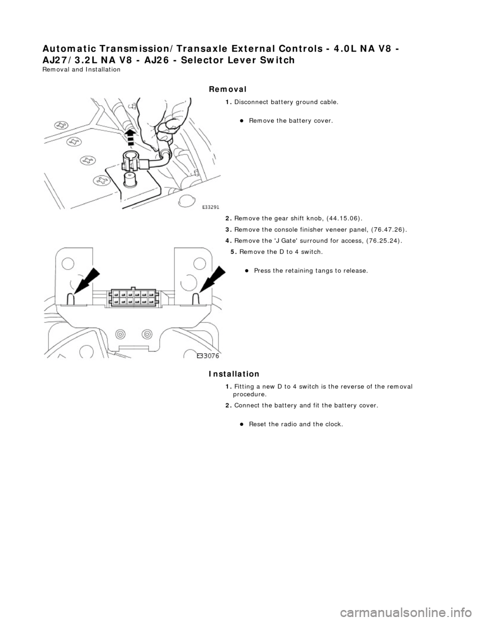
1. Disconnect battery ground cable.
Remove the battery cover.
2. Remove the gear shift knob, (44.15.06).
3. Remove the console finisher veneer panel, (76.47.26).
4. Remove the 'J Gate' surroun d for access, (76.25.24).
5. Remove the D to 4 switch.
Press the retaining tangs to release.
1. Fitting a new D to 4 switch is the reverse of the removal
procedure.
2. Connect the battery and fit the battery cover.
Reset the radio and the clock.