partic JAGUAR X308 1998 2.G User Guide
[x] Cancel search | Manufacturer: JAGUAR, Model Year: 1998, Model line: X308, Model: JAGUAR X308 1998 2.GPages: 2490, PDF Size: 69.81 MB
Page 1769 of 2490
Air Distribution and Filtering - Air Distri
bution and Filtering
Description an
d Operation
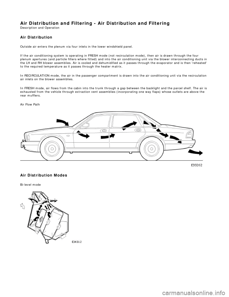
Air Distribution
Ou
tside air enters the plen
um via four inlets in the lower windshield panel.
If the air conditioning system is operating in FRESH mode (not recirculation mode), then air is drawn through the four
plenum apertures (and particle filters where fitted) and into the air conditioni ng unit via the blower interconnecting ducts in
the LH and RH blower assemblies. Air is c ooled and dehumidified as it passes through the evaporator and is then 'reheated'
to the required temperature as it passes through the heater matrix.
In RECIRCULATION mode, the air in the pass enger compartment is drawn into the air conditioning unit via the recirculation
air inlets on the blower assemblies.
In FRESH mode, air flows from the cabin into the trunk through a gap between the backlight and the parcel shelf. The air is
exhausted from the vehicle through extraction vent assemblies (incorporating one way flaps) whose outlets are above the
rear mufflers.
Air Flow Path
Air Distribution Modes
Bi
-level mode
Page 1771 of 2490
Air
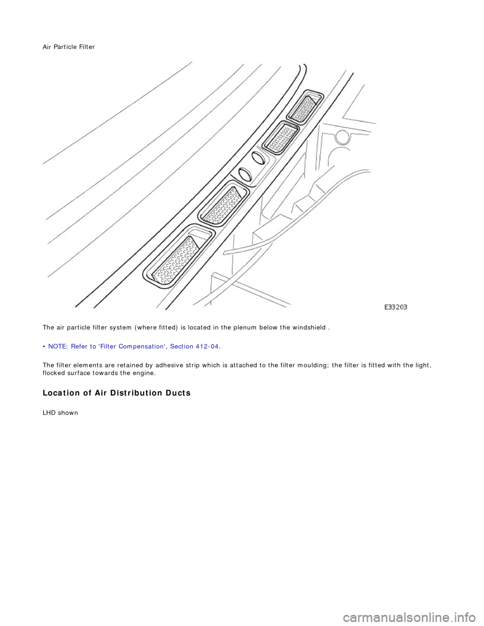
Particle Filter
The air particle filter system (where fitted) is located in the plenum below the windshield .
• NOTE: Refer to 'Filter Compensation', Section 412-04.
The filter elements are retained by adhesive strip which is atta ched to the filter moulding; the filter is fitted with the light,
flocked surface towards the engine.
Loca
tion of Air Distribution Ducts
LHD s
hown
Page 1784 of 2490
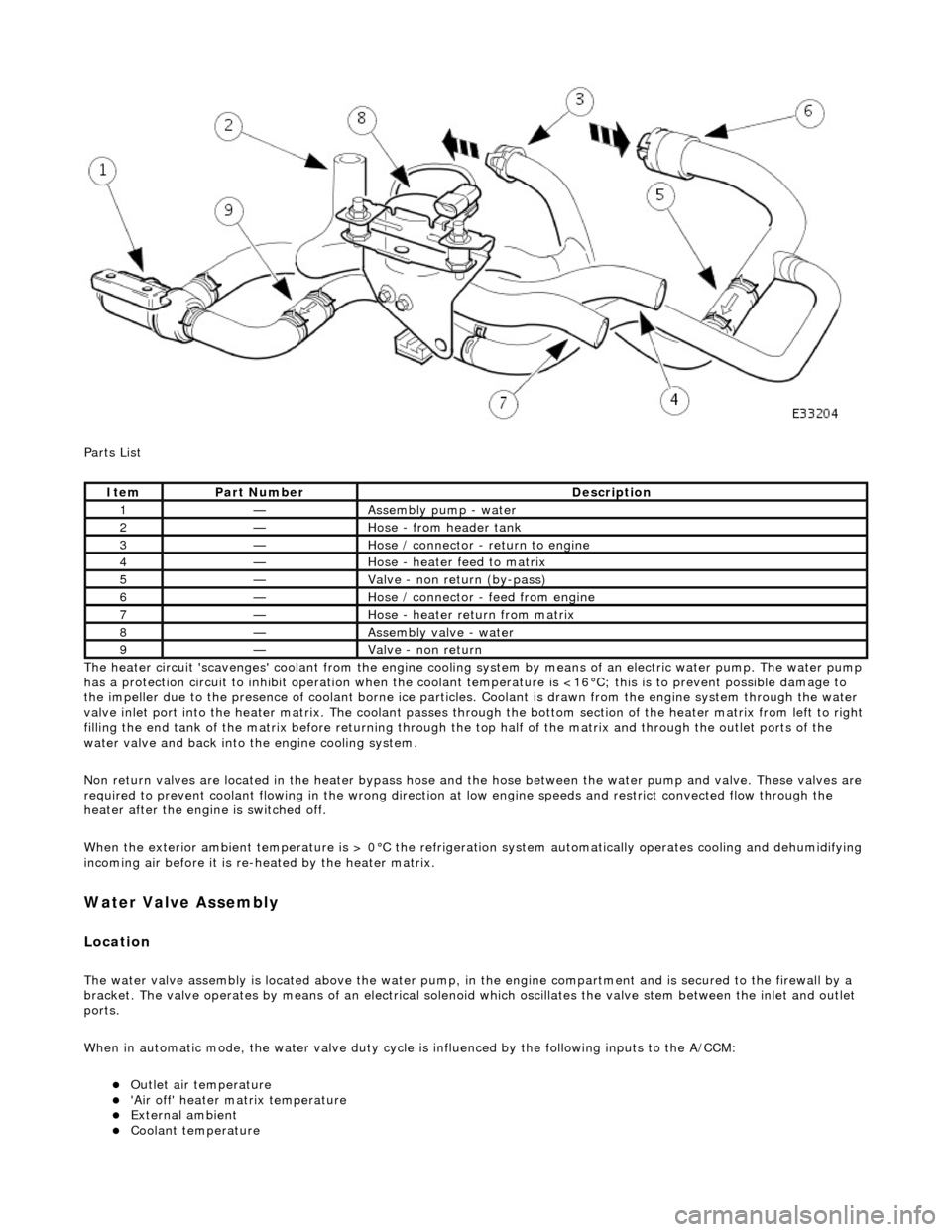
Parts List
The heater circuit 'scavenges' coolant from the engine cooling system by mean s of an electric water pump. The water pump
has a protection circuit to inhibit operation when the coolant temperature is <16°C; this is to prevent possible damage to
the impeller due to the presence of coolant borne ice particles. Coolant is drawn from the en gine system through the water
valve inlet port into the heater matrix. The coolant passes thro ugh the bottom section of the heater matrix from left to right
filling the end tank of the matrix before returning through the top half of the ma trix and through the outlet ports of the
water valve and back into the engine cooling system.
Non return valves are located in the heat er bypass hose and the hose between the water pump and valve. These valves are
required to prevent coolant flowing in th e wrong direction at low engine speeds and restrict convected flow through the
heater after the engine is switched off.
When the exterior ambient temperature is > 0°C the refrigerat ion system automatically operates cooling and dehumidifying
incoming air before it is re -heated by the heater matrix.
Water Valve Assembly
Location
The water valve assembly is located above the water pump, in the engine compartmen t and is secured to the firewall by a
bracket. The valve operates by means of an electrical solenoid which oscillates the valve stem between the inlet and outlet
ports.
When in automatic mode, the water valve duty cycle is influenced by the following inputs to the A/CCM:
Outlet air temperature 'Air off' heater matrix temperature External ambient Coolant temperature
ItemPart NumberDescription
1—Assembly pump - water
2—Hose - from header tank
3—Hose / connector - return to engine
4—Hose - heater feed to matrix
5—Valve - non return (by-pass)
6—Hose / connector - feed from engine
7—Hose - heater return from matrix
8—Assembly valve - water
9—Valve - non return
Page 1831 of 2490
other sensors. This feature prevents the effects of sudden changes in air outlet temperatures due to factors such as:
Recirculating air from the engine cooling pack at low vehicle speeds Sudden changes in ambient temperature The effects of water splash
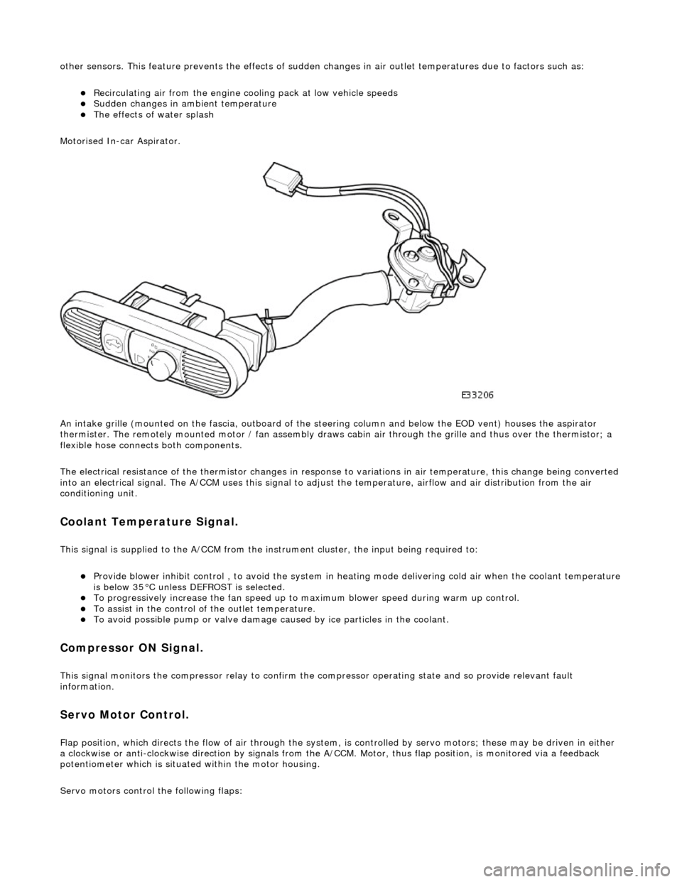
Motorised In-car Aspirator.
An intake grille (mounted on the fascia , outboard of the steering column and below the EOD vent) houses the aspirator
thermister. The remotely mounted motor / fan assembly draws ca bin air through the grille and thus over the thermistor; a
flexible hose connects both components.
The electrical resistance of the thermistor changes in response to variations in air temperatur e, this change being converted
into an electrical signal. The A/CCM uses this signal to adjust the temperature, airflow and air distribution from the air
conditioning unit.
Coolant Temperature Signal.
This signal is supplied to the A/CCM from the instrument cluster, the input being required to:
Provide blower inhibit control , to avoid the system in heat ing mode delivering cold air when the coolant temperature is below 35°C unless DEFROST is selected. To progressively increase the fan speed up to maximum blower speed during warm up control. To assist in the control of the outlet temperature. To avoid possible pump or valve damage ca used by ice particles in the coolant.
Compressor ON Signal.
This signal monitors the compressor relay to confirm the compressor operating state and so provide relevant fault
information.
Servo Motor Control.
Flap position, which directs the flow of air through the system, is controlled by servo motors; these may be driven in either
a clockwise or anti-clockwise direction by signals from the A/ CCM. Motor, thus flap position, is monitored via a feedback
potentiometer which is situated within the motor housing.
Servo motors control the following flaps:
Page 1832 of 2490
RH and LH Air Intake (Fresh / Recirc) Center Vent Defrost Foot Cool Air Bypass
Blower Motor Control.
The A/CCM controls the speed of two blower motors which deliver airflow to the air conditioning unit. The blower motors are
regulated by power transistor modules which pr ovide a linear variation of blower speed.
Filter Compensation
Where particle filters are fitted as 'after market' items the A/CCM program must be changed to allow higher AUTO blower
speeds; this compensates for the slight loss of air flow. Access to the program is by PDU.
Vehicles with filters fitted OEM will have this facility enabled by Jaguars Cars Ltd.
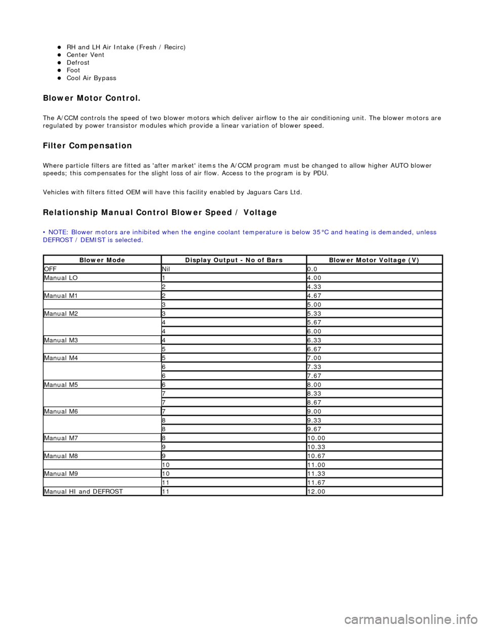
Relationship Manual Contro l Blower Speed / Voltage
• NOTE: Blower motors are inhibited when the engine coolant temperature is below 35°C and heating is demanded, unless
DEFROST / DEMIST is selected.
Blower ModeDisplay Output - No of BarsBlower Motor Voltage (V)
OFFNil0.0
Manual LO14.00
24.33
Manual M124.67
35.00
Manual M235.33
45.67
46.00
Manual M346.33
56.67
Manual M457.00
67.33
67.67
Manual M568.00
78.33
78.67
Manual M679.00
89.33
89.67
Manual M7810.00
910.33
Manual M8910.67
1011.00
Manual M91011.33
1111.67
Manual HI and DEFROST1112.00
Page 1919 of 2490
Exterior Lighting - Exterior Lighting
Description and Operation
A multi-function switch located on the left stalk of the steering column switch assembly permits selection of either parking
(side), headlamps, auto-headlamp or off. Selection of a particular mode provides the appropriate input to the body
processor module (BPM).
Where the auto headlamp function is incorporated, a light sensor in the interior rear view mirror monitors ambient light and
provides an input to the BPM. The BPM responds by switching the low beam headlamps on or off as appropriate for the
prevailing light conditions.
The front and rear fog lamp switch is located on the fascia outboard of the steering column.
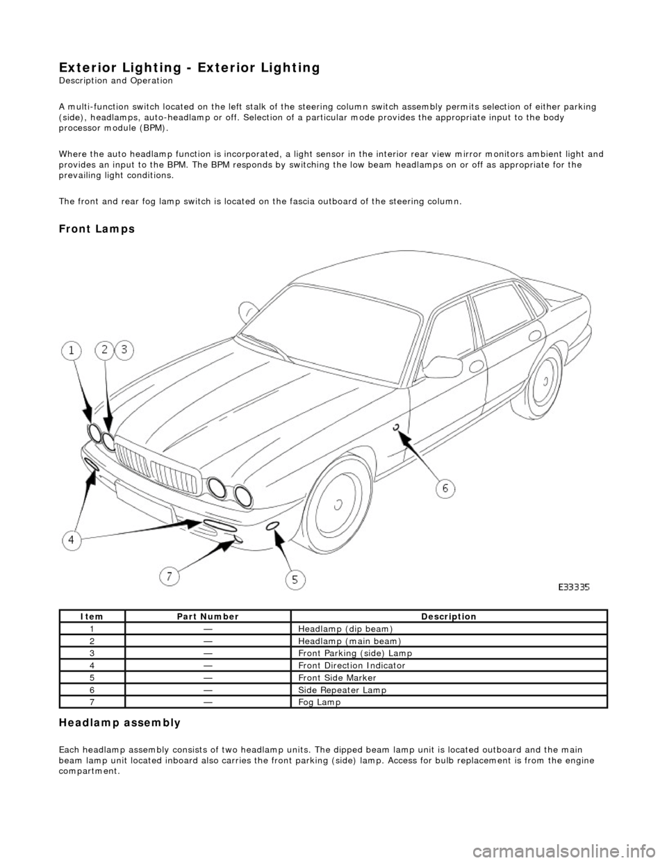
Front Lamps
Headlamp assembly
Each headlamp assembly consists of tw o headlamp units. The dipped beam lamp unit is located outboard and the main
beam lamp unit located inboard also carries the front parking (side) lamp. Access for bulb replacement is from the engine
compartment.
ItemPart NumberDescription
1—Headlamp (dip beam)
2—Headlamp (main beam)
3—Front Parking (side) Lamp
4—Front Direction Indicator
5—Front Side Marker
6—Side Repeater Lamp
7—Fog Lamp
Page 1990 of 2490

the bag securely before opening another bag. Also, replace the bag in its mating part number compartment within the case.
The pre-terminated wiring harness(s) are su pplied with the insulation in one of three colors, red, blue or yellow. The colors
do not apply to any particular circuit but to the harness wire size. See the Relationship Table in the Repair Method section.
Butt splice connectors are also supplied wi th red, blue or yellow coverings, which must be matched to the pre-terminated
wiring harness insulation color.
Pre-Terminated Wiring Harness(s)
Page 1992 of 2490
The part number of the pre-terminated wiring harness The letter showing the extractor tip which must be used to remove this type of electrical connector terminal Those electrical connector terminals which are gold
Some of the pre-terminated wiring harness( s) have seals installed to the insulation for sealed connector applications. It is
essential for prevention of mo isture ingress that a sealed pre-terminated wiring harness must be used where a sealed
terminal was removed.
CAUTION: Where the repair procedure indica tes that a glue lined heat shrink sleeve should be applied, apply sufficient
heat to the glue lined heat shrink to melt the glue in order to provide a water tight seal. Do not over heat the glue lined
heat shrink sleeve so that the wiring harness insulation becomes damaged.
Two sizes of heat shrink sleeving are supplied in the wiring harn ess repair kit. Each heat shrink sleeve contains a sealant
glue. These must be used when connecting wiring harness(s) or electrical connector terminal(s) at all times. The smaller
diameter heat shrink sleeve is to be used with the red and blue butt splice connectors and the larger di ameter sleeve with
the yellow butt sp lice connectors.
For ease and speed, some of the pre-term inated wiring harness(s) may already have the insulation partly stripped at the
splice end. If the repair requires insula tion to be stripped from the cable, refer to the Relationship Table fo r the correct
length of insulation to be stripped.
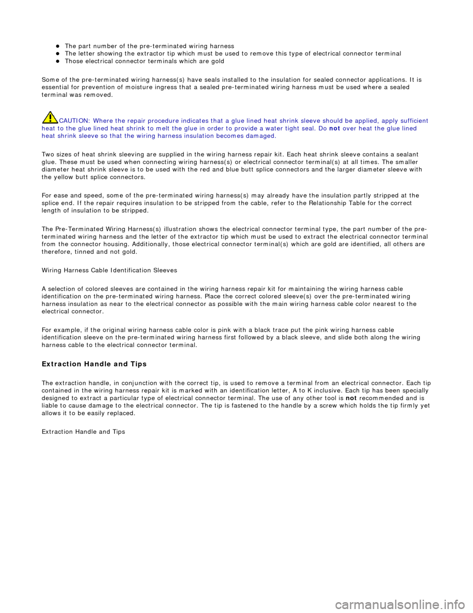
The Pre-Terminated Wiring Harness(s) illu stration shows the electrical connector terminal type, the part number of the pre-
terminated wiring harness and the letter of the extractor tip which must be used to extract the electrical connector terminal
from the connector housing. Additionally, those electrical conne ctor terminal(s) which are gold are identified, all others are
therefore, tinned and not gold.
Wiring Harness Cable Identification Sleeves
A selection of colored sleeves are contai ned in the wiring harness repair kit for maintaining the wiring harness cable
identification on the pre-term inated wiring harness. Place the correct colo red sleeve(s) over the pre-terminated wiring
harness insulation as near to the electr ical connector as possible with the main wiring harness cable color nearest to the
electrical connector.
For example, if the original wiring harness cable color is pink with a black trace put the pink wiring harness cable
identification sleeve on the pre-terminated wiring harness first followed by a black sleeve, and slide both along the wiring
harness cable to the electr ical connector terminal.
Extraction Handle and Tips
The extraction handle, in conjunction with th e correct tip, is used to remove a terminal from an elec trical connector. Each tip contained in the wiring harness repair kit is marked with an identification letter, A to K inclusive. Each tip has been special ly
designed to extract a particular ty pe of electrical connector terminal. The use of any other tool is not recommended and is
liable to cause damage to the electrical connector. The tip is fastened to the handle by a screw which holds the tip firmly yet
allows it to be easily replaced.
Extraction Handle and Tips
Page 2179 of 2490
Glass, Frames and Mechanisms - Glass, Frames and Mechanisms
Description and Operation
Fixed Glass
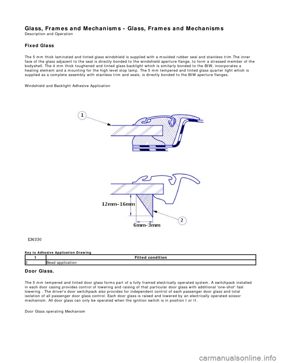
The 5 mm thick laminated and tinted glas s windshield is supplied with a moulded rubber seal and stainless trim.The inner
face of the glass adjacent to the seal is directly bonded to the windshield aperture flange, to form a stressed member of the
bodyshell. The 4 mm thick toughened and tinted glass backlight which is similarly bonded to the BIW, incorporates a
heating element and a mounting for the high level stop lamp. The 5 mm tempered and tinted glass quarter light which is
supplied as a complete assembly with stainless trim and seals, is directly bonded to the BIW aperture flanges.
Windshield and Backlight Adhesive Application
Key to Adhesive Application Drawing
Door Glass.
The 5 mm tempered and tinted door glass forms part of a fully framed electrically operated system. A switchpack installed
in each door casing provides control of lowering and raising of that particular d oor glass with additional 'one-shot' fast
lowering . The driver's door switchpack also provides for independent control of each passenger door glass and total
isolation of all passenger door glass control. Each door glas s is raised and lowered by an electrically operated scissor
mechanism. All door glass can only be operated wh en the ignition switch is in position I or II.
Door Glass operating Mechanism
1Fitted condition
2Bead application
Page 2383 of 2490
Paint
The inhalation of sprays, fumes, or dust during paint application or sanding processes should always be avoided. Ensure
that there is efficient ventilation / extrac tion at all times. Paint spraying should be confined as far as possible to spray
booths. Personnel with a history of asth ma should not be employed in any process involving the use of isocyanates.
Operators working in a spray booth where isocyanate material is present must use air-fed breathing equipment with air
supplied to the visor at the re commended pressure and filtered to remove oil, water, and fumes. Operators involved in
handling mixing or spraying should wear protective clothing including gloves and goggles, to avoid skin and eye contact.
Particle masks or canister type respir atosr should be worn when sanding.
Applied Heat
When welding, flame cutting, brazing etc, the operator shou ld use as appropriate, goggles, mask / fume extractor and
flameproof protective clothing. It is especially important when working with polyurethane compounds to use air-fed
breathing equipment. Appropriat e fire fighting equipment and personnel trai ned in its use must always be available.
Metal Repair
Appropriate eye and hand protection should be worn when sanding, drilling, cutting, chiselling, flatting or welding. Face
masks or air-fed visors should also be wo rn when sanding or flatting either body solder or fillers. On completion of a
soldering operation, swarf must be re moved from the work area and the operat or must wash his hands thoroughly.
GENERAL REPAIR NOTES
The following advice should be noted before any repair work is carried out.
Disconnect the vehicle battery gr ound lead (disconnect the alternator where electric welding is used) and take note of the
reconnection procedures as detailed in 86.15.15.
Where structural parts are straightened or renewed, a body alignment / straightening jig must be used. The application of
heat, especially excessive heat, reduces the strength of steels, where appropriate therefore, structural sections should be
straightened by cold processes.
Repairs may only be carried out successful ly, and any warranties protected, if genuine Jaguar replacement parts and Jaguar
approved materials are used.
The correct tools, procedures and facilities must always be us ed. The quality of the work must not be compromised by using
inappropriate methods or equipment.
All trim and electrical components in the locality of the repair must be removed or disconnected prior to panel removal /
replacement; this is especially important where hollow sectio ns may contain harnesses, tubes or foam, see section A4.3.5.
WARNING: DO NOT WORK IN THE VICINITY OF A LIVE AIR BAG, REMOVE IT COMPLETELY. READ WORKING
PRACTICES AIR BAG, SECTION 20. ANY SEAT BELT WHICH HAS BEEN WORN IN AN ACCIDENT MUST BE RENEWED.
CAUTION: Electric arc welding should not be used on Jaguar vehicles. The high voltages produced by this process will
cause irreparable damage to the electric al control and microprocessor systems.
The following welding and gas processes are the only ones recommended by Jaguar Cars Ltd.
Welding and Gas Processes
Resistance spot welding, MIG welding and all gas processes may only be carried out on bare, unpainted or unplated metal.
The flanges of panels to be welded toge ther, must be clean, corrosion free and tr eated as appropriate, with either weld-
through primer or inter-weld sealer. Only materials and processes specified in the 'Body Sealing and Preservation Manual'
should be used in the relevant application areas detailed in this section. Refer to 'Zinc Coated Panels' Section