partic JAGUAR X308 1998 2.G Owner's Manual
[x] Cancel search | Manufacturer: JAGUAR, Model Year: 1998, Model line: X308, Model: JAGUAR X308 1998 2.GPages: 2490, PDF Size: 69.81 MB
Page 2384 of 2490

Generally, resistance spot welding equipment used in the motor vehicle repair industry does not produce welds of equivalent strength to those achieved during manufactu re. The expression 'single row of resistance spot welds' indicates that the spots
should be spaced on a pitch of 19mm to 25mm, which normally results in mo re spot welds than those produced in the
original factory joint.
Resistance spot welds should be removed using a resistance spot weld cutter. If the new joint is to be MIG plug welded, old
resistance spot welds should be cut from the panel to be reta ined and the resulting holes used for plug welding. Suitable
holes may also be drilled or punched; 8,0 mm dia for sect ions up to 1,6 mm, and 10,0 mm dia for thicker sections.
PLASTICS-EXPLANATORY NOTES
Plastic component and trim materials
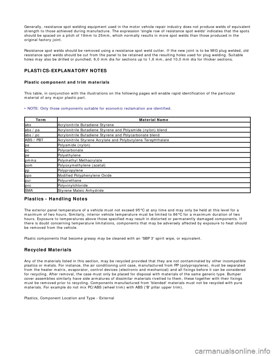
This table, in conjunction with the illu strations on the following pages will enable rapid identification of the particular
material of any major plastic part.
• NOTE: Only those components suitable for economic reclamation are identified.
Plastics - Handling Notes
The exterior panel temperature of a vehicle must not exceed 95°C at any time and may only be held at this level for a
maximum of two hours. Similarly, interior vehicle temperatur e must be limited to 86°C for a maximum duration of two
hours. Exposure to temperatures above those specified may result in distorted or permanently damaged components. If
there is doubt concerning temperature limitations, components that may be adversel y affected by exposure to heat should
be removed from the vehicle.
Plastic components that become greasy may be clea ned with an 'SBP 3' spirit wipe, or equivalent.
Recycled Materials
Any of the materials listed in this section, may be recycled provided that they ar e not contaminated by other incompatible
plastics or metals. For instan ce, the air conditioning unit case, manufactur ed from PP (polypropylene), must be separated
from the heater matrix, evaporator, contro l devices (electronic and mechanical) and all fixings before it can be considered
for recycling. After removal, the case mu st only be placed for disposal with materials of the same generic type. Bumper
cover assemblies similarly have side arma tures of dissimilar materials rivetted to them, these together with their fixings
must be removed prior to recy cling. Components manufactured from 'blended' materials must not be recycled with pure
materials. For example do not mix PC/ABS (wheel trim) with ABS ('B' pillar upper trim).
Plastics, Component Location and Type - External
TermMaterial Name
absAcrylonitrile Butadiene Styrene
abs / paAcrylonitrile Butadiene Styrene and Polyamide (nylon) blend
abs / pcAcrylonitrile Butadiene Styrene and Polycarbonate blend
ABS / PBTAcrylonitrile Styrene Acrylate and Polybutylene Terephthalate
paPolyamide (nylon)
pcPolycarbonate
pePolyethylene
pmmaPolymethyl Methacrylate
pomPolyoxymethylene (acetal)
ppPolypropylene
ppoModified Polyphenylene Oxide
purPolyurethane
pvcPolyvinylchloride
SMAStyrene Maleic Anhydride
Page 2391 of 2490

ZINC COATED PANELS
Description
Approximately 70% of the 'body in white' (BIW) mass is made up of zinc coated panels.
• NOTE: To maintain the protective qualities of the zinc trea tment, repairs to any damaged coated area must be made as
soon as possible after the damage has occurred.
All exterior skin panels, with the exceptio n of the roof, are double side zinc plated and this coating (nominally 7,5 microns)
provides two way corrosion protection. Should the outer layer of paint become chipped with the zinc coating remain intact,
the zinc will oxidize on contact with air and being impermeable, this coat of oxidation will prevent corrosion damage of the
base metal. If the outer layer of paint and the zinc coating become damaged, the zinc rather than the base metal will react
with the air and 'sacrifice' itself to corrosion as a 'sacrificial anode'.
Welding Preparation
Contamination of the weld with resultant reduction in joint st rength increase and increased electrode tip dressing frequency
will occur zinc coating is not removed. In exceptional cases where the zinc coating must remain intact, the tip pressure and
welding current should be increased by 10 to 20%.
Where 'resistance spot welding' is employed, the zinc coatin g should be lightly abraded away on the mating surfaces and
those in contact with the electrode tips. Do not remove more zinc coating than is absolutely necessary.
Before welding, a weld-through primer or inter-weld sealer should be applied, as detailed in the Body Sealing and
Preservation manual.
Where MIG welding is used as an alternativ e to resistance spot welding for plug and butt welds or due to limited access, the
problems caused by the presence of zinc coating are much the same, with the added complication of increased weld spatter
and nozzle contamination.
Body Fillers
Conventional polyester fillers do not adhere satisfactorily to zinc plated panels, it is ther efore important that only those
products specifically designed for this application are used and the manufacturer's recommendations are followed.
Refinishing
Use only those products approved by Jaguar Cars Ltd and exercise special care on zinc coated panels.
As replacement panels ar e supplied ready primed, the only bare metal that needs to be exposed are those areas prepared
for welding etc, as decribed in 'Welding Preparation. Where any part of a panel is dressed back to the bare surface, it should
be treated with a zinc rich primer compatible with the paint application system.
GENERAL PREPARATION OF PANELS
Removal of Panels and Welds
• NOTE: Where other components must be removed for access, refer to the relevant manual section for guidance. This is
particularly important where steerin g, braking, suspension, electrical and safety systems are affected.
Expose all resistance spot welds, using a ro tary wire brush fitted to an air drill or a hand held wire brush on those that are
not clearly visible (1).
WARNING: DO NOT BURN UNDERSEAL OFF. USE A 'HOT KNIFE' OR SUITABLE SOLVENT.
Cut out spot welds using a Zipcutter or Roto-Bor (2). At this point it may be necessary to cut out the bulk of the panel using
Page 2407 of 2490

For coachline specifications, see page? .
Tape Application
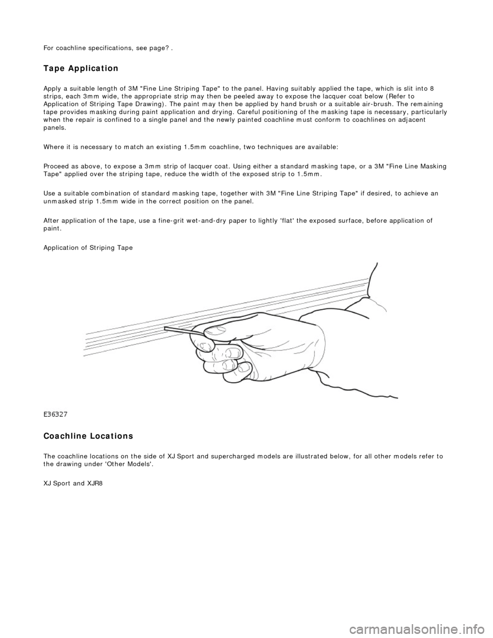
Apply a suitable length of 3M "Fine Line Striping Tape" to the panel. Having suitably applied the tape, which is slit into 8
strips, each 3mm wide, the appr opriate strip may then be peeled away to expose the lacquer coat below (Refer to
Application of Striping Tape Drawing). The paint may then be applied by hand brush or a suitable air-brush. The remaining
tape provides masking during paint applicat ion and drying. Careful positioning of the masking tape is necessary, particularly
when the repair is confined to a single panel and the newly painted coachline mu st conform to coachlines on adjacent
panels.
Where it is necessary to match an existing 1.5mm coachline, two tec hniques are available:
Proceed as above, to expose a 3mm strip of lacquer coat. Using either a standard masking tape, or a 3M "Fine Line Masking
Tape" applied over the striping tape, reduce the width of the exposed strip to 1.5mm.
Use a suitable combination of standard mask ing tape, together with 3M "Fine Line Striping Tape" if desired, to achieve an
unmasked strip 1.5mm wide in the correct position on the panel.
After application of the tape, use a fine-g rit wet-and-dry paper to lightly 'flat' the exposed surface, before application of
paint.
Application of Striping Tape
Coachline Locations
The coachline locations on the side of XJ Sport and supercharged models are illustrated below, for all other models refer to
the drawing under 'Other Models'.
XJ Sport and XJR8
Page 2417 of 2490

Panels centered between two adjacent panels must have equal gaps on either side. For exceptions to this, refer to the
appropriate specification. Gaps between ad jacent panels or components must not expose harnesses, labels, brackets or
visually poor joint or assembly conditions.
• NOTE: Sliding roof panel clearances are specified without the edge seal installed.
Areas of particular concern are, fuel filler flap, trunk lid to fenders and saddle panels, hood to fenders, grill and headlamps,
sliding roof to main roof panel, door gaps at fenders, B\C posts, roof drip rail an d rocker panel, and bumper cover to fenders
and cross car assemblies
Alignment
Panels must be correctly profiled to maintain cosmetic appearance, and ensure co rrect seating of seals with minimal wind
noise. Areas of particular concern are hood to fenders, trunk lid to fenders and saddle panels, doors to apertures, doors to
fenders and adjacent doors and relationship of the sliding roof panel leading and trailing edges to the main roof panel.
Exterior Fitments
Bezels, trims and lamps must be concentric with apertu res and have equal clearances with adjacent panels.
Areas of particular concern are headlamp to hood, fender and trim panel, exhaust tailpipe trim to bumper cover cut-out,
rear lamp assembly to trunk lid, fender and bumper cover trim, and side feature lines including body side mouldings, fender
to door and door to door.
Exterior Clearances and Alignments-Front