JAGUAR X308 1998 2.G Workshop Manual
Manufacturer: JAGUAR, Model Year: 1998, Model line: X308, Model: JAGUAR X308 1998 2.GPages: 2490, PDF Size: 69.81 MB
Page 2101 of 2490

Exterior Trim and Ornamentation - A-Pillar Moulding RH
Removal and Installation
Removal
Installation
1.
Remove rear grab handle. Refer to 76.58.30.
2. Remove draught welt from adjace nt section of door aperture
flange.
3. Using a trim removal tool, carefu lly ease the six trim pad fir
tree fasteners from cantrail an d upper'A' post locations.
4. If premium ICE is fitt ed, carefully withdraw trim pad for access
and disconnect tweeter connectors.
5. Remove trim pad from vehicle an d remove tweeter. Refer to
415-03.
6. Remove and discard fir tree fasteners.
1. Fit new fir tree fasten ers to the trim pad.
2. Fit tweeter to trim pad. Refer to Section 415.
3. Position trim pad for access and connect tweeter to harness.
4. Commencing at top of 'A' post and working rearwards, fully
seat three fir tree fasteners.
5. Fully seat remaining three fir tr ee fasteners in upper'A' post.
6. Fit grab handle. Refer to 76.58.30.
7. Fit draught welt to adjacent section of door aperture flange.
Page 2102 of 2490

Exterior Trim and Ornamentation - Coachlines
Removal and Installation
Removal
Installation
1.
For removal of painted coachlines , refer to Section 501-18 of
this manual.
1. For position and application of painted coachlines, refer to
Section 501-18 of this manual.
Page 2103 of 2490

Exterior Trim and Ornamentation - Door Moulding
Removal and Installation
Removal
Installation
1.
Apply suitable protecti ve tape to immediately adjacent areas of
paintwork.
2. Using a hand-held heat gun, appply heat uniformly along
moulding length.
3. Applying local heat at one end and using a suitable thin lever
to avoid damaging paintwork, progressively ease moulding
away from door panel.
4. Discard moulding and remove protective tape.
5. Remove any residual adhesive and thoroughly clean area using
white spirit.
1. NOTE: Optimum adhesion is achi eved by warming body panel
and moulding to 65deg C.
Using white spirit ensure that mounting area is clean, dry and
de-greased.
2. Remove protective backing tape from moulding.
3. NOTE: Do not allow moulding to contact the body panel until it
is correctly aligned.
Heat moulding and moun ting area to 65degC.)
4. Aligning with adjacent mouldings or to match opposite side of
vehicle, press new moulding firmly onto body panel.
5. Apply hand pressure along moulding length to ensure
satisfactory adhesion.
6. Allow moulding and door panel to cool , then thoroughly clean
both using white spirit.
7. Apply a coat of suitab le polish to moulding and body panel.
Page 2104 of 2490

Exterior Trim and Ornamentation - Front Fender Moulding
Removal and Installation
Removal
Installation
1.
Apply suitable protecti ve tape to immediately adjacent areas of
paintwork.
2. Using a hand-held heat gun, appply heat uniformly along
moulding length.
3. Applying local heat at one end and using a suitable thin lever
to avoid damaging paintwork, progressively ease moulding
away from fender.
4. Discard moulding and remove protective tape.
5. Remove any residual adhesive and thoroughly clean area using
white spirit.
1. NOTE: Optimum adhesion is achi eved by warming body panel
and moulding to 65deg C.
Using white spirit ensure that mounting area is clean, dry and
de-greased.
2. Remove protective backing tape from moulding.
3. NOTE: Do not allow moulding to contact the fender until it is
correctly aligned.
Heat moulding and mounting area to 65deg C.
4. Aligning with adjacent mouldings or to match opposite side of
vehicle, press new mouldi ng firmly onto fender.
5. Apply hand pressure along moulding length to ensure
satisfactory adhesion.
6. Allow moulding and fender to cool , then thoroughly clean both
using white spirit.
7. Apply a coat of suitable poli sh to moulding and fender.
Page 2105 of 2490

Exterior Trim and Ornamentation - Luggage Compartment Lid Badges
Removal and Installation
Removal
Installation
1.
Apply protective tape to area immediately surrounding and up
to the badge edge.
2. Using a thin plastic lever and a fulcrum of suitable material
positioned on the taped area, carefully ease the badge free.
3. Remove protective tape.
4. Using white spirit, remove any residual adhesive.
1. Ensure that contact area is clean and dry.
2. Remove backing sheet from badge.
3. Ensuring correct alig nment with trunk lid recess and where
applicable lock aperture and pr ess badge firmly into position.
4. Clean affected area and apply su itable polish to trunk lid and
badge.
Page 2106 of 2490

Exterior Trim and Ornamentation - Luggage Comp artment Lid Moulding
Removal and Installation
Removal
1. Remove battery cover and disc onnect ground cable from
battery terminal. Refer to 86.15.19.
2. Disconnect and remove trunk lamp assemblies. Refer to
86.45.16.
3. Remove covers from trunk latc h finisher securing bolts,
slacken and remove bolts and remove finisher.
4. Remove and discard trunk li d liner rear fasteners and
position liner for access.
5. Free trunk lid release button harness from retaining clip and
disconnect multiplug.
6. NOTE: The pressed steel fasteners fitted to Jaguar models
should be discarded on removal.
Slacken and remove nuts/fasteners securing trim finisher to
trunk lid.
Page 2107 of 2490

Installation
7. Position trim finisher for a ccess and withdraw and discard
release button harness grommet from trunk lid.
8. Remove trim finisher from trunk lid.
9. Carefully remove seal from trim finisher.
10. Slacken and remove screws securing release button assembly
to trim finisher and remove release button from finisher.
1. Fit and fully seat release button in trim finisher and fit and
tighten securing screws.
2. Apply suitable adhesive to contac t area of trim finisher and fit
and align seal to finisher.
3. Position trim finisher and pass release button harness through
trunk lid aperture.
Page 2108 of 2490

4.
Fit and fully seat a new harn ess grommet in trunk lid.
5. NOTE: Fit new pressed steel fasteners on Jaguar models.
Align and fully seat trim finisher on trunk lid and fit and fully
tighten securing nuts/fasteners.
6. Connect release button harness multiplug and position harness
in retaining clip.
7. Position and fully seat trunk li d trim pad and secure with new
fir tree fasteners.
8. Fit finisher over trunk latch, fi t and tighten securing bolts and
fit bolt covers..
9. Fit trunk lamp assemblies. Refer to 86.45.16.
10. Connect ground cable to batt ery terminal and fit battery
cover. Refer to 86.15.15.
Page 2109 of 2490

Exterior Trim and Ornamentation - Radiator Grille
Removal and Installation
Removal
Installation
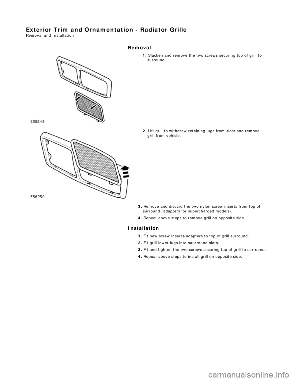
1. Slacken and remove the two scre ws securing top of grill to
surround.
2. Lift grill to withdraw retainin g lugs from slots and remove
grill from vehicle.
3. Remove and discard the two ny lon screw inserts from top of
surround (adapters for su percharged models).
4. Repeat above steps to remove grill on opposite side.
1. Fit new screw inserts/adapters to top of grill surround.
2. Fit grill lower lugs into suurround slots.
3. Fit and tighten the two screws securing top of grill to surround.
4. Repeat above steps to instal l grill on opposite side.
Page 2110 of 2490

Exterior Trim and Ornamentation - Radiator Grille Bezel
Removal and Installation
Removal
Installation
1.
Remove radiator grills for access. Refer to 76.55.03.
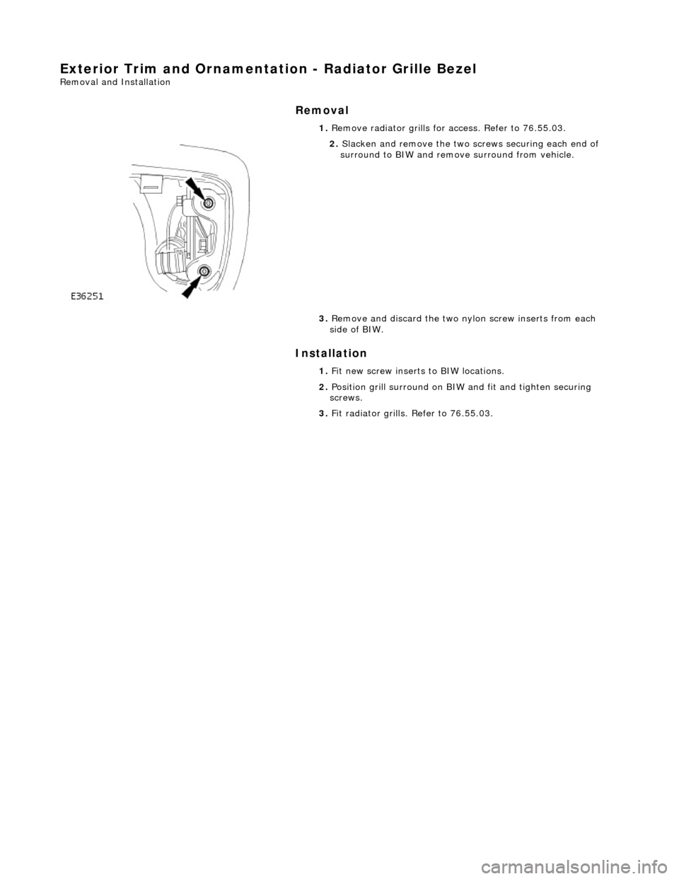
2. Slacken and remove the two screws securing each end of
surround to BIW and remove surround from vehicle.
3. Remove and discard the two nylon screw inserts from each
side of BIW.
1. Fit new screw inserts to BIW locations.
2. Position grill surround on BIW and fit and tighten securing
screws.
3. Fit radiator grills. Refer to 76.55.03.