Steering column JAGUAR X308 1998 2.G Workshop Manual
[x] Cancel search | Manufacturer: JAGUAR, Model Year: 1998, Model line: X308, Model: JAGUAR X308 1998 2.GPages: 2490, PDF Size: 69.81 MB
Page 8 of 2490

В В В В В В В В В В В В 211‐02: В Powe rВ Steering В
В В В В В В В В В В В В В В В В Specif
ication
В
В В В В В В В В В В В В В В В В Description В and В Operation В
В В В В В В В В В В В В В В В В В В В В PowerВ SteeringВ
В В В В В В В В В В В В В В В В Diagnosis В and В Testing В
В В В В В В В В В В В В В В В В В В В В PowerВ SteeringВ
В В В В В В В В В В В В В В В В RemovalВ and В Installation В
В В В В В В В В В В В В В В В В В В В В SteeringВ Gear В (57.10.01) В
В В В В В В В В В В В В В В В В В В В В SteeringВ Gear В Bushing В (57.10.30) В
В
В В В В В В В В В В В В 211‐03: В SteeringВ LinkageВ
В В В В В В В В В В В В В В В В Specification В
В В В В В В В В В В В В В В В В Description В and В Operation В
В В В В В В В В В В В В В В В В В В В В SteeringВ Linkage В
В
В В В В В В В В В В В В 211‐04: В SteeringВ ColumnВ
В В В В В В В В В В В В В В В В Specification В
В В В В В В В В В В В В В В В В Description В and В Operati
onВ
В В В В В В В В В В В В В В В В В В В В SteeringВ Column В
В В В В В В В В В В В В В В В В RemovalВ and В Installation В
В В В В В В В В В В В В В В В В В В В В SteeringВ ColumnВ LowerВ Shaft В (57.40.05) В
В
В В В В В В В В В В В В 211‐05: В SteeringВ ColumnВ Switches В
В В В В В В В В В В В В В В В В Specification В
В В В В В В В В В В В В В В В В Description В and В Operation В
В В В В В В В В В В В В В В В В В В В В SteeringВ ColumnВ Switches В
В В В В В В В В В В В В В В В В RemovalВ and В Installation В
В В В В В В В В В В В В В В В В В В В В SteeringВ ColumnВ Multifunction В Switch В (86.65.92) В
В
В В В В 3: В PowertrainВ
В
В В В В В В В В 303: В Engine В
В
В В В В В В В В В В В В 303‐00: В Engine В System  ‐ General В Information В
В В В В В В В В В В В В В В В В
В В В В В В В В В В В В В В В В В В В В В
Page 32 of 2490

В В В В В В В В В В В В В В В В В В В В RearВ CupВ Holder В (76.25.27) В
В В В В В В В В В В В В В В В В В В В В SteeringВ Col u
mnВ
Lower В Shroud В (76.46.03) В
В В В В В В В В В В В В В В В В В В В В SteeringВ ColumnВ UpperВ Shroud В (76.46.02) В
В
В В В В В В В В В В В В 501‐14: В Handles, В Locks,В Latches В and В Entry В Systems В
В В В В В В В В В В В В В В В В Description В and В Operation В
В В В В В В В В В В В В В В В В В В В В Handles,В Locks,В Latches В and В Entry В Systems В
В В В В В В В В В В В В В В В В RemovalВ and В Installation В
В В В В В В В В В В В В В В В В В В В В ExteriorВ Driver В Door В Handle В (76.58.07) В
В В В В В В В В В В В В В В В В В В В В DriverВ DoorВ LatchВ (76.37.74) В
В В В В В В В В В В В В В В В В В В В В GloveВ CompartmentВ LidВ Ha
ndleВ (76.52.08) В
В В В В В В В В В В В В В В В В В В В В GloveВ CompartmentВ LidВ Lock В Cylinder В (76.52.23) В
В В В В В В В В В В В В В В В В В В В В LuggageВ CompartmentВ LidВ Latch В (76.19.25) В
В В В В В В В В В В В В В В В В В В В В LuggageВ CompartmentВ LidВ Latch В Actuator В (76.19.25) В
В В В В В В В В В В В В В В В В В В В В LuggageВ CompartmentВ LidВ Release В Switch В (86.25.56) В
В В В В В В В В В В В В В В В В В В В В LuggageВ CompartmentВ LidВ Warning В IndicatorВ SwitchВ (86.65.93) В
В В В В В В В В В В В В В В В В В В В В ExteriorВ Passenger В Door В Handle В (76.58.08) В
В В В В В В В В В В В В В В В В В В В В PassengerВ Door В Latch В (76.37.75) В
В В В В В В В В В В В В В В В В В В В В ExteriorВ Rear В Door В Handle В (76.58.02) В
В В В В В В В В В В В В В В В В В В В В RearВ Door В Latch В (76.37.09) В
В
В В В В В В В В В В В В 501‐16: В Wipers В and В Washers В
В В В В В В В В В В В В В В В В Descriptio
nВ and В Operation В
В В В В В В В В В В В В В В В В В В В В WipersВ andВ Washers В
В В В В В В В В В В В В В В В В RemovalВ and В Installation В
В В В В В В В В В В В В В В В В В В В В HeadlampВ WasherВ Jet В (84.20.08) В
В В В В В В В В В В В В В В В В В В В В HeadlampВ WasherВ Pump В (84.20.21) В
В В В В В В В В В В В В В В В В В В В В RainВ Sensor В (84.12.10) В (86.56.62) В
В В В В В В В В В В В В В В В В В В В В Windshield В Washer В Pump В (84.10.21) В
В В В В В В В В В В В В В В В В В В В В Windshield В Washer В Reservoir В (84.10.01) В (84.10.03) В
В В В В В В В В В В В В В В В В В В В В Windshield В Wiper В Motor В (84.15.13) В
В В В В В В В В В В В В В В В В В В В В Windshield В Wiper/
Washer В Switch В (86.65.42) В
В В В В В В В В В В В В В В В В В В В В WiperВ Pivot В Arm В (84.15.03) В
В
В В
Page 67 of 2490
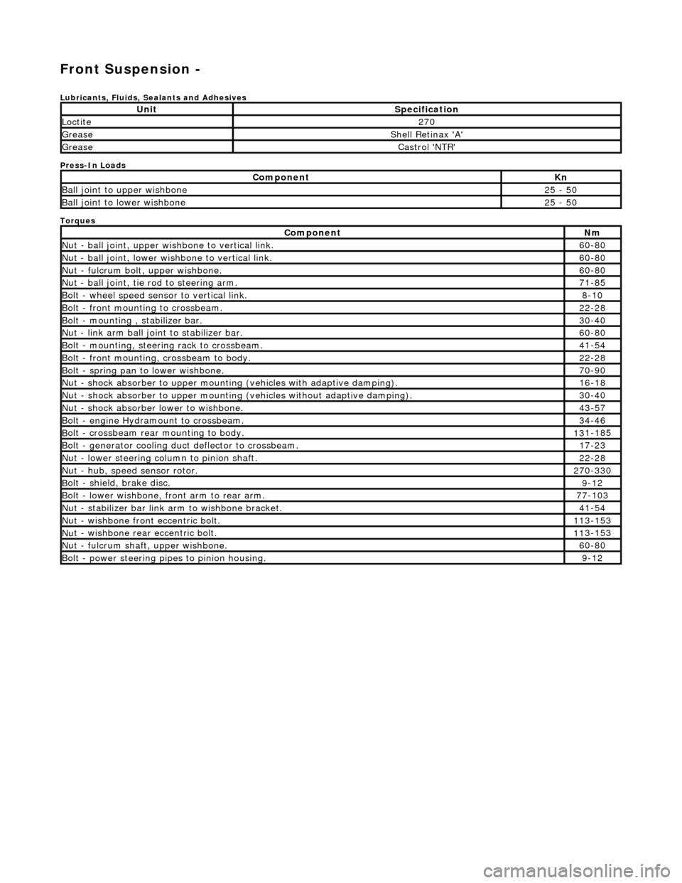
Front Suspension -
Lubri
cants, Fluids, Sealants and Adhesives
Press-In Loads
Torques
UnitS
pecification
Loctite27
0
Greas
e
Shell Retin
ax 'A'
Greas
e
Castro
l 'NTR'
Com
ponent
Kn
Ball join
t to upper wishbone
25
- 50
B
all joint to lower wishbone
25
- 50
Com
ponent
Nm
N
ut - ball joint, upper wishbone to vertical link.
60
-80
N
ut - ball joint, lower wishbone to vertical link.
60
-80
Nu
t - fulcrum bolt, upper wishbone.
60
-80
N
ut - ball joint, tie rod to steering arm.
71
-85
Bol
t - wheel speed sensor to vertical link.
8-1
0
Bol
t - front mounting to crossbeam.
22
-28
Bolt
- mounting , stabilizer bar.
30
-40
N
ut - link arm ball joint to stabilizer bar.
60
-80
Bolt
- mounting, steering rack to crossbeam.
41
-54
B
olt - front mounting, crossbeam to body.
22
-28
Bol
t - spring pan to lower wishbone.
70
-90
N
ut - shock absorber to upper mounting
(vehicles with adaptive damping).
16
-18
Nu
t - shock absorber to upper mounting (vehicles without adaptive damping).
30
-40
N
ut - shock absorber lower to wishbone.
43
-57
B
olt - engine Hydramount to crossbeam.
34
-46
B
olt - crossbeam rear mounting to body.
13
1-185
Bol
t - generator cooling du
ct deflector to crossbeam.
17
-23
N
ut - lower steering column to pinion shaft.
22
-28
N
ut - hub, speed sensor rotor.
27
0-330
B
olt - shield, brake disc.
9-1
2
Bol
t - lower wishbone, front arm to rear arm.
77
-103
Nu
t - stabilizer bar link arm to wishbone bracket.
41
-54
N
ut - wishbone front
eccentric bolt.
11
3-153
Nu
t - wishbone rear
eccentric bolt.
11
3-153
N
ut - fulcrum shaft, upper wishbone.
60
-80
Bolt -
power steering pi
pes to pinion housing.
9-1
2
Page 83 of 2490
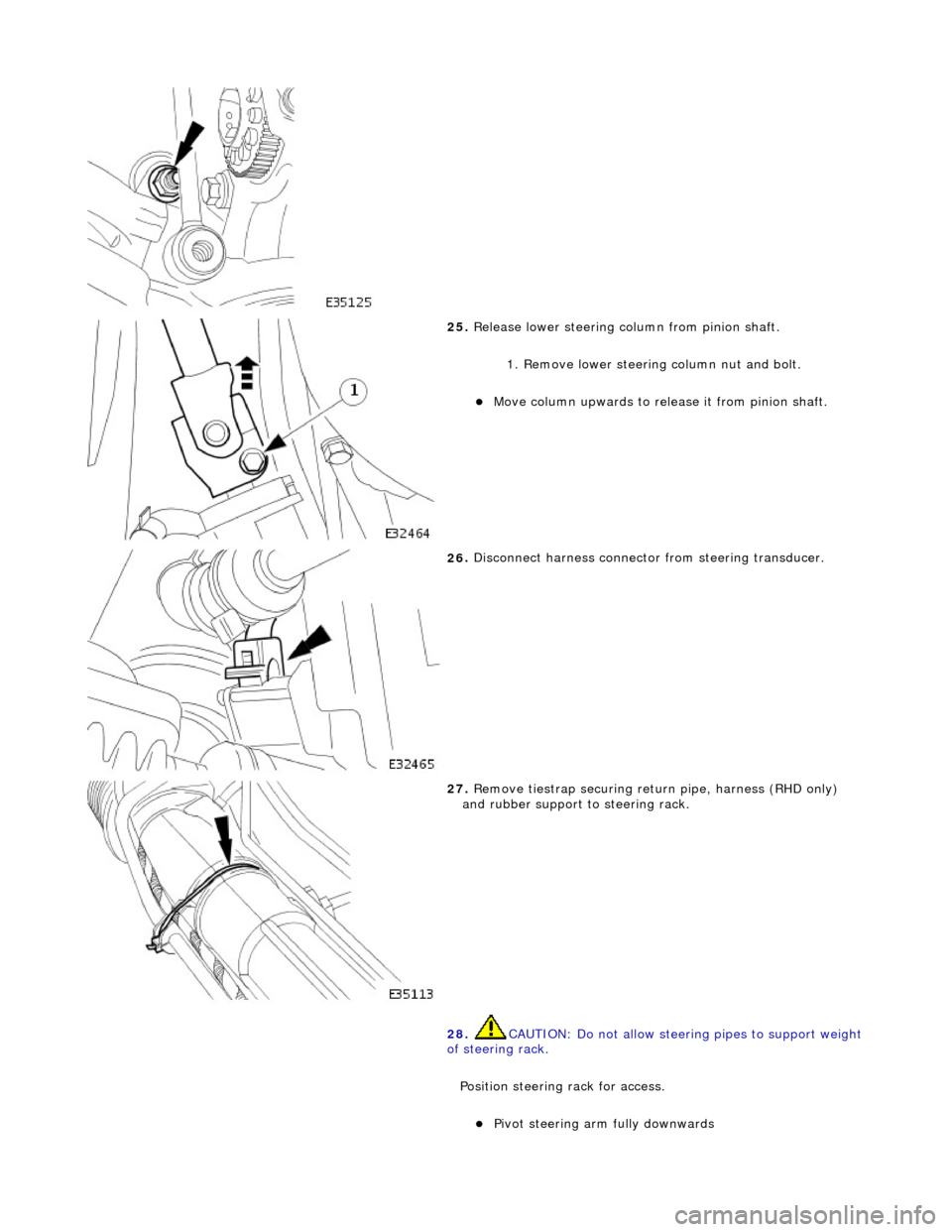
25
.
Release lower steering column from pinion shaft.
1. Remove lower steering column nut and bolt.
пЃ¬Move column up
wards to release it from pinion shaft.
26
.
Disconnect harness connector from steering transducer.
27
.
Remove tiestrap securing retu rn pipe, harness (RHD only)
and rubber support to steering rack.
28. CAUTION: Do not allow steerin g pipes to support weight
of steering rack.
Position steering rack for access.
пЃ¬Pi
vot steering arm fully downwards
Page 84 of 2490

In
stallation
пЃ¬Re
move steering rack securing bolts.
пЃ¬Carefully move steer
ing rack
downwards for access to
wishbone eccentric bolt.
29 . R
emove lower wishbone rear
arm eccentric bolt and nut.
пЃ¬Mark position of eccentri
c bo
lt large graduation mark on
crossbeam.
пЃ¬R e
move wishbone rear ec
centric bolt and nut.
30. Remove lower wishbone rear arm/ball joint assembly from
crossbeam.
1. Positi
on wishbone rear arm on crossbeam and install but do
not tighten eccentric bolt.
2. Install steeri
ng rack on crossbeam.
пЃ¬Ensure
that b
ushes are correct
ly positioned on steering
rack.
пЃ¬Posi ti
on steering rack on crossbeam.
пЃ¬Position support brac
kets over bus
hes.
пЃ¬Install mountin
g bracket bolts an
d tighten to 41-54Nm.
3. Install lower steering column on pinion shaft.
пЃ¬Move col u
mn downwards to engage coupling splines on
pinion shaft.
Page 95 of 2490
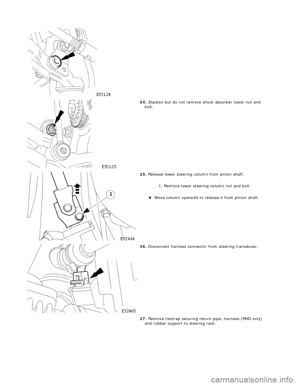
24
.
Slacken but do not remove shock absorber lower nut and
bolt.
25
.
Release lower steering column from pinion shaft.
1. Remove lower steering column nut and bolt.
пЃ¬Move column up
wards to release it from pinion shaft.
26
.
Disconnect harness connector from steering transducer.
27. Remove tiestrap securing retu rn pipe, harness (RHD only)
and rubber support to steering rack.
Page 98 of 2490

not ti
ghten eccentric bolt and nut.
4. Install steeri
ng rack on crossbeam.
пЃ¬Ensure that b
ushes are correct
ly positioned on steering
rack.
пЃ¬Posi ti
on steering rack on crossbeam.
пЃ¬Position support brac
kets over bus
hes.
пЃ¬Install mountin
g bracket bolts an
d tighten to 41-54Nm.
5. Inst al
l lower steering column on pinion shaft.
пЃ¬Move col
u
mn downwards to engage coupling splines on
pinion shaft.
1. Install nut and bolt and tighten to 22-28Nm.
6. Position an d
connect harnes
s to steering transducer.
пЃ¬RHD veh
icles. Position steeri
ng harness behind return
pipe.
пЃ¬Conne ct
harness to transducer.
7. Secure return pipe on steering rack.
1. Position pipe rubber support on steering rack.
2. Position pipe on support .
3. RHD vehicles. Position harness on pipe support rubber.
Page 455 of 2490
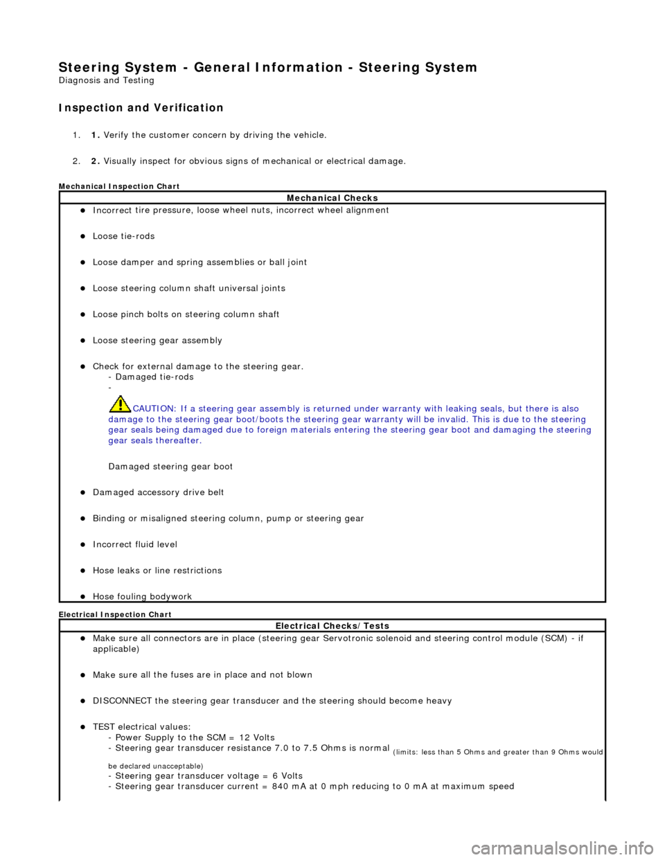
Steering System - General Inform
ation - Steering System
D
iagnosis and Testing
I
nspection and Verification
1.
1. Verify t
he customer concern by driving the vehicle.
2. 2. Visually inspect for obvious signs of mechanical or electrical damage.
Mec
hanical Inspection Chart
Electrical Inspection Chart
Mechanical Checks
пЃ¬Incorrect
tire pressure, loose whee
l nuts, incorrect wheel alignment
пЃ¬Loose ti
e-rods
пЃ¬Loose dam
per and spring assemblies or ball joint
пЃ¬Loose s
teering column shaft universal joints
пЃ¬Loose pinc
h bolts on steering column shaft
пЃ¬Loose steeri
ng gear assembly
пЃ¬Check f
or external damage to the steering gear.
- Damaged tie-rods
-
CAUTION: If a steering gear assemb ly is returned under warranty with leaking seals, but there is also
damage to the steering gear boot/boots the steering gear warranty will be invalid. This is due to the steering
gear seals being damaged due to fore ign materials entering the steering gear boot and damaging the steering
gear seals thereafter.
Damaged steering gear boot
пЃ¬Damaged accessory driv
e belt
пЃ¬Bin
ding or misaligned steering co
lumn, pump or steering gear
пЃ¬Incorrect fluid
level
пЃ¬Hose leaks o
r line restrictions
пЃ¬Hose fou
ling bodywork
El
ectrical Checks/Tests
пЃ¬Make sure all
connectors are in plac
e (steering gear Servotronic solenoid and steering control module (SCM) - if
applicable)
пЃ¬Make su
re all the fuses are in place and not blown
пЃ¬D
ISCONNECT the steering gear transducer
and the steering should become heavy
пЃ¬TEST e
lectrical values:
- Power Supply to the SCM = 12 Volts
- Steering gear transducer resist ance 7.0 to 7.5 Ohms is normal
(
limits: less than 5 Ohms and greater than 9 Ohms would
be declared unacceptable)
- Steeri
ng gear transducer voltage = 6 Volts
- Steering gear transducer cu rrent = 840 mA at 0 mph reducing to 0 mA at maximum speed
Page 457 of 2490
•
NOTE: The following steps must be carried out with assistance.
1. 1. With the wheels in the straight ahead po sition, gently turn the steering wheel to the left and the right to check for
free play.
2. 2. Free play should be between 0 and 6 mm (0 and 0.24 in) at the steering wheel rim. If the free play exceeds this
limit, either the ball joints are worn, the lower steering column joints are worn or the backlash of the steering gear
is excessive.
CAUTION: DO NOT attempt to adjust the stee ring gear yoke. Failure to follow this instruction will result in the steering
gear warranty to become invalid.
3. 3. The backlash of the steering gear cannot be adjusted, in stall a new steering gear. For additional information,
REFER to Section 211
-0
2 Power Steering
.
4. 4. Grasp the steering wheel
firm
ly and move it up and down and to the left and right without turning the wheel to
check for column bearing wear, steering wheel or steering column. For additional information,
REFER to Section 211
-0
4 Steering Column
.
Power Steering Fluid Condition Check
1.
1. R
un the engine for 2 minutes.
2. 2. Check the power steering fluid system level.
3. 3. Observe the color and the odor. The color under normal circumstances should be dark reddish, not brown or
black.
4. 4. Allow the fluid to drip onto a faci al tissue and examine the stain.
5. 5. If evidence of solid material is foun d, the power steering fluid system should be drained for further inspection.
6. 6. If fluid contamination or steering co mponent failure is confirmed by the se diment in the power steering fluid
system, REFER to Steering Fault Diagnosis by Symptom Charts in this section.
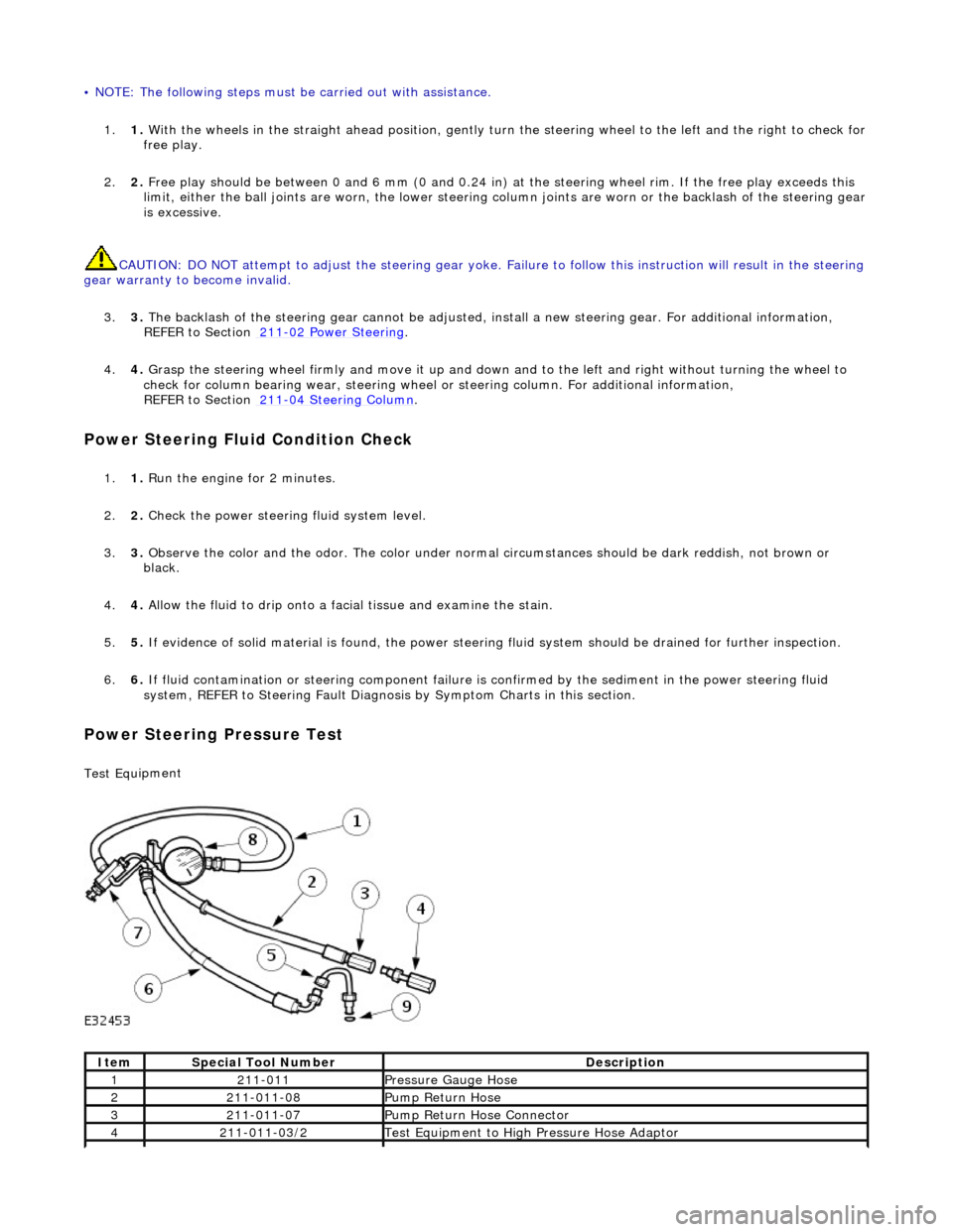
Power Steer
ing Pressure Test
Test Equ
ipment
It
em
S
pecial Tool Number
De
scription
12
11-011
Pres
sure Gauge Hose
221
1-011-08
Pump Return Hose
321
1-011-07
Pump Return Hose Connector
42
11-011-03/2
Test Equ
ipment to High
Pressure Hose Adaptor
Page 459 of 2490
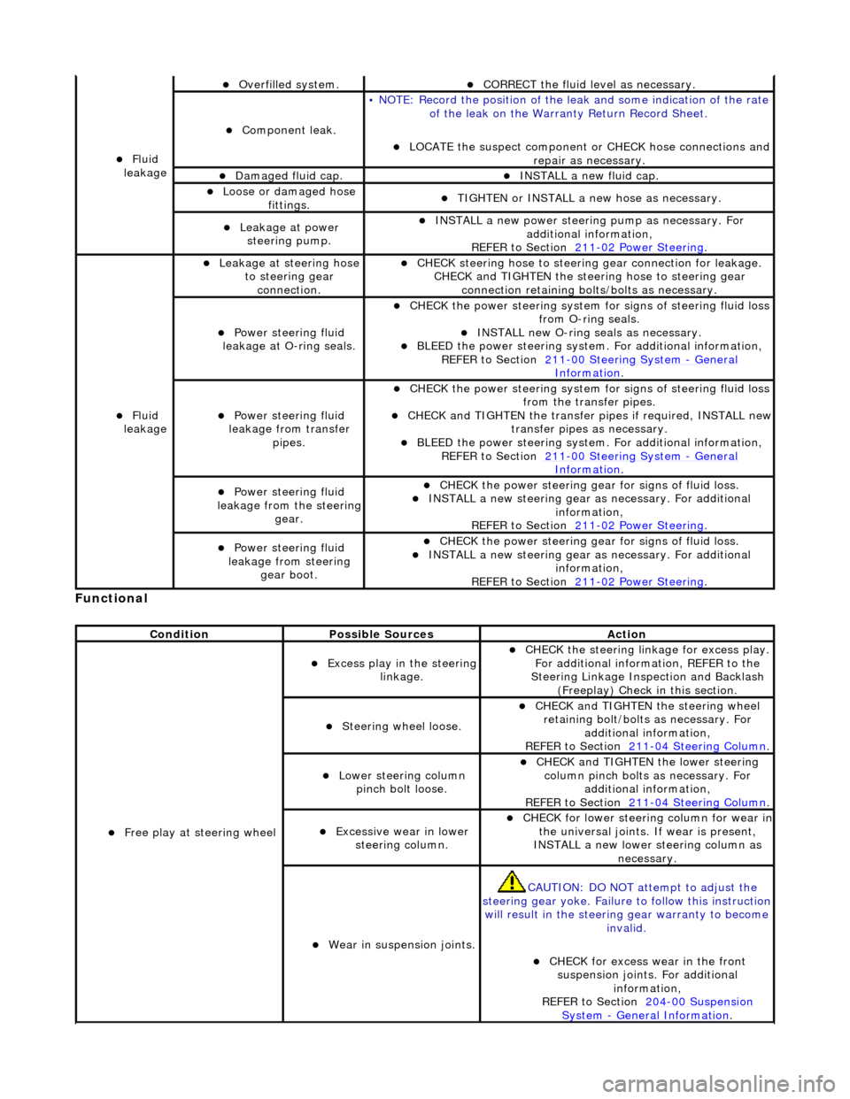
Function
al
пЃ¬Fl
uid
leakage
пЃ¬O
verfilled system.
пЃ¬CORRECT the
fluid leve
l as necessary.
пЃ¬Compon
ent leak.
•
NOTE: Record the position of the le
ak and some indication of the rate
of the leak on the Warra nty Return Record Sheet.
пЃ¬LOCATE
the suspect component or CHECK hose connections and
repair as necessary.
пЃ¬Damaged fluid cap. пЃ¬INST
ALL a new fluid cap.
пЃ¬Loose or damaged h
ose
fittings.
пЃ¬TI
GHTEN or INSTALL a new hose as necessary.
пЃ¬Leakage at
power
steering pump.
пЃ¬INST
ALL a new power steering
pump as necessary. For
additional information,
REFER to Section 211
-0
2 Power Steering
.
пЃ¬Fl
uid
leakage
пЃ¬Leakage
at steering hose
to steering gear connection.
пЃ¬CHECK
steering hose to
steering gear conn ection for leakage.
CHECK and TIGHTEN the steeri ng hose to steering gear
connection retaining bolt s/bolts as necessary.
пЃ¬Power steeri
ng fluid
leakage at O-ring seals.
пЃ¬CHECK
the power steering system fo
r signs of steering fluid loss
from O-ring seals.
пЃ¬INST
ALL new O-ring seals as necessary.
пЃ¬BLEE
D the power steering system.
For additional information,
REF
ER to Section 211
-0
0 Steering System
- Ge
neral
Informati
on
.
пЃ¬Power steeri
ng fluid
leakage from transfer pipes.
пЃ¬CHECK
the power steering system fo
r signs of steering fluid loss
from the transfer pipes.
пЃ¬CHECK
and TIGHTEN the transfer pipes if required, INSTALL new
transfer pipes as necessary.
пЃ¬BLEE
D the power steering system.
For additional information,
REF
ER to Section 211
-0
0 Steering System
- Ge
neral
Informati
on
.
пЃ¬Power steeri
ng fluid
leakage from the steering
gear.
пЃ¬CHECK
the power steering gear for signs of fluid loss.
пЃ¬INST
ALL a new steering gear as
necessary. For additional
information,
REFER to Section 211
-0
2 Power Steering
.
пЃ¬Power steeri
ng fluid
leakage from steering gear boot.
пЃ¬CHECK
the power steering gear for signs of fluid loss.
пЃ¬INST
ALL a new steering gear as
necessary. For additional
information,
REFER to Section 211
-0
2 Power Steering
.
Cond
ition
Possib
le Sources
Acti
on
пЃ¬F
ree play at steering wheel
пЃ¬Exce
ss play in the steering
linkage.
пЃ¬CHECK
the steering linkage for excess play.
For additional information, REFER to the
Steering Linkage Inspection and Backlash (Freeplay) Check in this section.
пЃ¬S
teering wheel loose.
пЃ¬CHECK
and TIGHTEN the steering wheel
retaining bolt/bolts as necessary. For additional information,
REFER to Section 211
-0
4 Steering Column
.
пЃ¬Lower steeri
ng column
pinch bolt loose.
пЃ¬CHECK
and TIGHTEN the lower steering
column pinch bolts as necessary. For additional information,
REFER to Section 211
-0
4 Steering Column
.
пЃ¬Exce
ssive wear in lower
steering column.
пЃ¬CHECK
for lower steering column for wear in
the universal joints. If wear is present,
INSTALL a new lower steering column as necessary.
пЃ¬W
ear in suspension joints.
CAU
TION: DO NOT attempt to adjust the
steering gear yoke. Failure to follow this instruction
will result in the steering gear warranty to become
invalid.
пЃ¬CHECK
for excess wear in the front
suspension joints. For additional information,
REFER to Section 204
-00
Suspension
Sy
stem
- General
Information
.