lamp JAGUAR X308 1998 2.G Workshop Manual
[x] Cancel search | Manufacturer: JAGUAR, Model Year: 1998, Model line: X308, Model: JAGUAR X308 1998 2.GPages: 2490, PDF Size: 69.81 MB
Page 25 of 2490

Rear Door Speaker (86.50.14)
Rear Door Tweeter Speaker (86.50.62)
Subwoofer
Speaker (86.51.05)
417: Lighting
417‐01: Exterior Lighting
Specification
Description and Operation
Exterior Lighting
Diagnosis and Testing
Exterior Lighting
Removal and Installation
Brake Pedal Position (BPP) Switch
Fog Lamp Switch (86.65.10)
Front Fog Lamp (86.
40.96)
Front Fog Lamp Bulb (86.40.94)
Front Side Marker Lamp (86.40.59)
Front Side Marker Lamp Bulb (86.40.58)
Front Turn Signal Lamp Bulb (86.40.41)
Headlamp Assembly (86.41.33)
Headlamp Leveling Motor (86.42.04)
High Beam Headlamp (86.41.34)
High Beam Headlamp Bulb (86.40.12)
High Mounted Stoplamp (86.41.01) (86.41.32)
High Mo
unted Stoplamp Bulb (86.41.02)
License Plate Lamp (86.40.86)
License Plate Lamp Bulb (86.40.85)
Low Beam Headlamp (86.41.35) ‐ Vehicles Without: Headlamp Leveling
Low Beam Headlamp (86.41.35) ‐ Vehicles With: Headlamp Leveling
Low Beam Headlamp Bulb (86.40.08)
Rear Lamp Assembly (86.40.70)
Rear Lamp Assembly Bulb (86.40.73)
Rear Side Marker La
mp (86.41.08)
Rear Side Marker Lamp Bulb (86.41.07)
Side Lamp Bulb (86.40.27)
Side Lamp/Front Turn Signal Lamp (86.40.39)
Page 26 of 2490

Side Turn Signal Lamp (86.41.41)
Side Turn Signal Lamp Bulb (86. 41.42)
417‐02
:
Interior Lighting
Specification
Description and Operation
Interior Lighting
Diagnosis and Testing
Interior Lighting
Removal and Installation
Door Courtesy Lamp (86.40.38)
Door Courtesy Lamp Bulb (86.40.47)
Door Courtesy Lamp Lens (86.40.35)
Glove Co
mpartment Lamp (86.45.08)
Luggage Compartment Lamp (86.45.16)
Vanity Mirror Lamp (76.10.50)
417‐04: Daytime Running Lamps (DRL)
Description and Operation
Daytime Running Lamps (DRL)
Diagnosis and Testing
Daytime Running Lamps (DRL)
418: Electrical Distribution
418‐00: Module Communications Network
Description and Operation
Communications Ne
twork
Removal
and Installation
Battery
Junction Box (BJB) (86.70.69)
Central
Junction Box (CJB) (86.70.72)
Front
Auxiliary Junction Box (86.70.73)
Rear
Auxiliary Junction Box (86.70.74)
418 ‐02: Wiring Harnesses
Description and Operati
on
Wiring Harness
General Procedures
Wiring Harness Repair
Page 32 of 2490

Rear Cup Holder (76.25.27)
Steering Col u
mn
Lower Shroud (76.46.03)
Steering Column Upper Shroud (76.46.02)
501‐14: Handles, Locks, Latches and Entry Systems
Description and Operation
Handles, Locks, Latches and Entry Systems
Removal and Installation
Exterior Driver Door Handle (76.58.07)
Driver Door Latch (76.37.74)
Glove Compartment Lid Ha
ndle (76.52.08)
Glove Compartment Lid Lock Cylinder (76.52.23)
Luggage Compartment Lid Latch (76.19.25)
Luggage Compartment Lid Latch Actuator (76.19.25)
Luggage Compartment Lid Release Switch (86.25.56)
Luggage Compartment Lid Warning Indicator Switch (86.65.93)
Exterior Passenger Door Handle (76.58.08)
Passenger Door Latch (76.37.75)
Exterior Rear Door Handle (76.58.02)
Rear Door Latch (76.37.09)
501‐16: Wipers and Washers
Descriptio
n and Operation
Wipers and Washers
Removal and Installation
Headlamp Washer Jet (84.20.08)
Headlamp Washer Pump (84.20.21)
Rain Sensor (84.12.10) (86.56.62)
Windshield Washer Pump (84.10.21)
Windshield Washer Reservoir (84.10.01) (84.10.03)
Windshield Wiper Motor (84.15.13)
Windshield Wiper/
Washer Switch (86.65.42)
Wiper Pivot Arm (84.15.03)
Page 42 of 2490
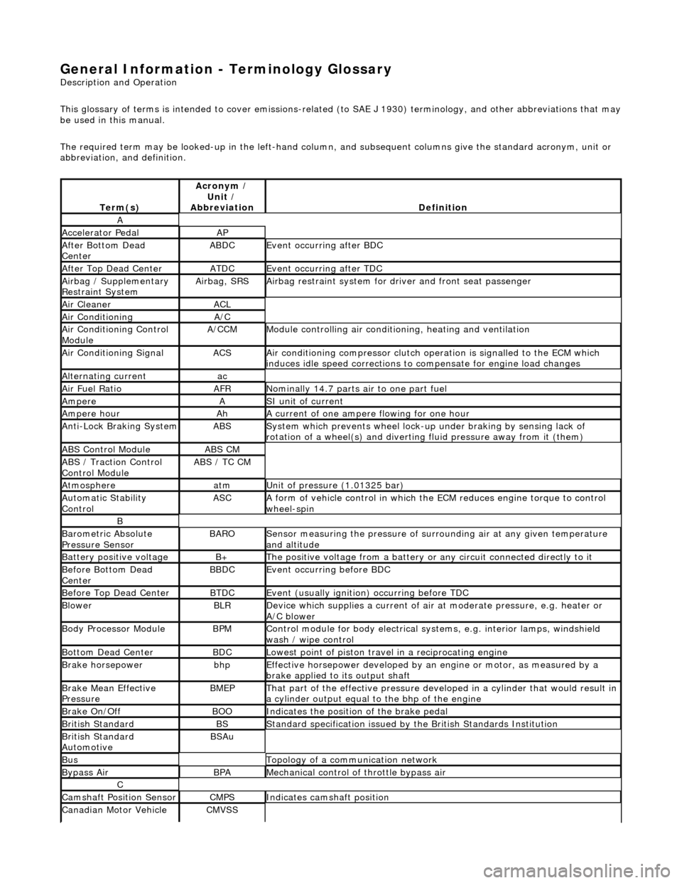
General Information - Terminology Glossary
Description an
d Operation
This glossary of terms is intended to cover emissions-related (to SAE J 1930) term inology, and other abbreviations that may
be used in this manual.
The required term may be looked-up in th e left-hand column, and subsequent columns give the standard acronym, unit or
abbreviation, and definition.
Te rm
(s)
Acr
ony
m /
Unit /
Abbreviation
De fi
nition
A
Accel
e
rator Pedal
AP
Af
ter Botto
m Dead
Center
ABDCEvent occurri ng after
BDC
Af
ter Top Dead CenterATDCEvent occurri ng after
TDC
Ai
rbag /
Supplementary
Restraint System
Airbag, SRSAi rbag restraint system for
dr
iver and front seat passenger
Air Cleane rACL
Air ConditioningA/C
Air Conditioning Con t
rol
Module
A/CCMModule c
ontrolling air conditioning, heating and ventilation
Air Conditioning SignalACSA
i
r conditioning compressor clutch operation is signalled to the ECM which
induces idle speed corrections to co mpensate for engine load changes
Alternating cu
rrent
ac
Ai
r Fuel R
atio
AFRN
omi
nally 14.7 parts air to one part fuel
Ampe
reASI unit of current
Ampere hourAhA current of one ampere
fl
owing for one hour
Anti-Lock Braking SystemABSS
y
stem which prevents wheel lock-up
under braking by sensing lack of
rotation of a wheel(s) and divertin g fluid pressure away from it (them)
ABS Control Mo
dule
ABS CM
ABS /
T
raction Control
Control Module
ABS / T
C CM
Atmosph
e
re
atmU
n
it of pressure (1.01325 bar)
Au
to
matic Stability
Control
ASCA form of vehicle
control
in which the ECM reduces en gine torque to control
wheel-spin
B
Baro me
tric Absolute
Pressure Sensor
BAR OSensor measuring the pressure of surr ou
nding air at any given temperature
and altitude
Bat t
ery positive voltage
B+The posi
ti
ve voltage from a battery or
any circuit connected directly to it
Before Bottom Dead
CenterBBDCEvent occurri ng before BD
C
Before Top Dead
Center
BTD
CEvent (usual ly
ignition) occurring before TDC
Blowe
rBLRDe
vice which supplies a current of air at
moderate pressure, e.g. heater or
A/C blower
Body Processor M
odule
BPMControl modu
le
for body electrical systems, e.g. interior lamps, windshield
wash / wipe control
Bott om D
ead Center
BD
CLowest poin t of piston
travel in a reciprocating engine
Brake hors
epowe
r
bhpEffecti
ve horsepower devel
oped by an
engine or motor, as measured by a
brake applied to its output shaft
Brake Mean Effective
Pres sureBME PThat p
art of the effective
pressure developed in a cyli nder that would result in
a cylinder output equal to the bhp of the engine
Brake On/ O
ff
BOOIn
dic
ates the position of the brake pedal
Br
it
ish Standard
BSStan
dar
d specification issued by the British Standards Institution
Br
it
ish Standard
Automotive
BSAu
BusTopology of a commu n
ication network
Bypass
AirBPAMechanica l
control of throttle bypass air
C
Camshaft Posit
i
on Sensor
CMPSIndi
cat
es camshaft position
Canadian Motor
V
ehicle
CMVSS
Page 44 of 2490
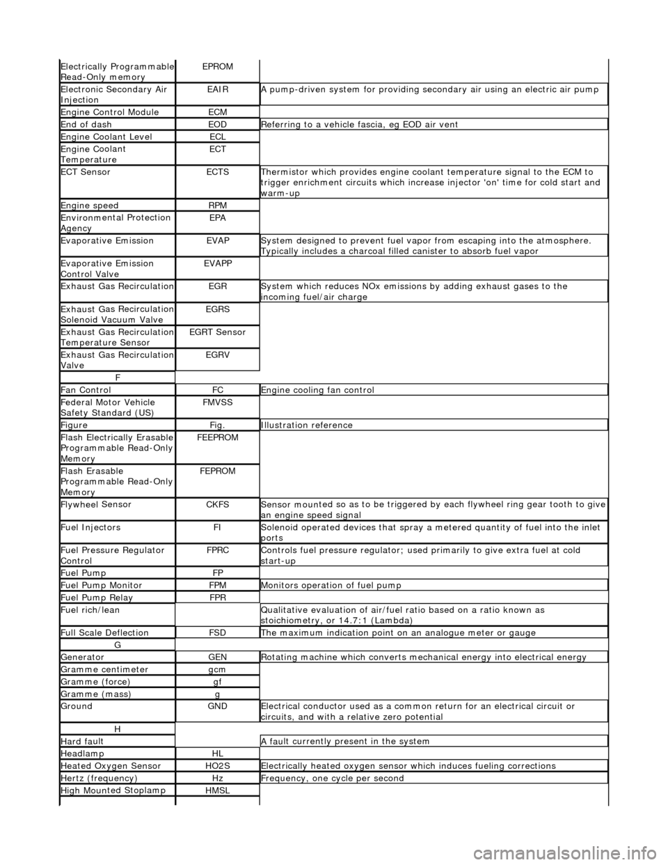
Electrically Programmable
R
ead-Only memory
EPROM
Ele
c
tronic Secondary Air
Injection
EAIRA p
ump-driven system for providing seco
ndary air using an electric air pump
Engine C
ontrol Module
ECM
End of dashEODR
e
ferring to a vehicle fascia, eg EOD air vent
Engine
C
oolant Level
ECL
Engine
C
oolant
Temperature
ECT
ECT Sen s
or
ECTSTherm
i
stor which provides engine coolant temperature signal to the ECM to
trigger enrichment circuits which increase injector 'on' time for cold start and
warm-up
Engine s
peed
RP
M
Environ m
ental Protection
Agency
EPA
Evaporative EmissionEVAPSy stem designed to prevent fu
el vapor from escaping into the atmosphere.
Typically includes a charcoal filled canister to absorb fuel vapor
Evaporative Emission
Control ValveEVAPP
Exhaust G
as Recirculation
EGRSys
t
em which reduces NOx emissions by adding exhaust gases to the
incoming fuel/air charge
Exhaus t G
as Recirculation
Solenoid Vacuum Valve
EGRS
Exhaus t G
as Recirculation
Temperature Sensor
EGRT Sen s
or
Exhaus
t G
as Recirculation
Valve
EGRV
F
F a
n Control
FCEngine
cooling fan control
F
e
deral Motor Vehicle
Safety Standard (US)
FMV S
S
Fi
gur
e
Fi
g.Illustrati
on reference
Flash
E
lectrically Erasable
Programmable Read-Only
Memory
FEE PR
OM
Flash
E
rasable
Programmable Read-Only
Memory
FEP R
OM
Flywhee
l
Sensor
CKFSSens
or moun
ted so as to be
triggered by each flywheel ring gear tooth to give
an engine speed signal
Fue l
Injectors
FISol
e
noid operated devices that spray a metered quantity of fuel into the inlet
ports
F u
el Pressure Regulator
Control
FP RCControls fuel pressure regu l
ator; used primarily to
give extra fuel at cold
start-up
Fue l
Pump
FP
Fue
l
Pump Monitor
FP
MMonitors operation of fuel pump
Fue l
Pump Relay
FP
R
Fu
el rich/lean
Q
u
alitative evaluation
of air/fuel ratio based on a ratio known as
stoichiometry, or 14.7:1 (Lambda)
F u
ll Scale Deflection
FSDTh
e
maximum indication point on
an analogue meter or gauge
G
Gene
rator
GENRot
a
ting machine which converts mechanical energy into electrical energy
G
r
amme centimeter
gcm
Gramm
e
(force)
gf
Gramm
e
(mass)
g
GroundGNDEle
c
trical conductor used
as a common return for an electrical circuit or
circuits, and with a relative zero potential
H
Hard f a
ult
A
fau
lt currently present in the system
HeadlampHL
Heat
ed Oxygen
Sensor
HO2SElectrically
h
eated oxygen sensor which induces fueling corrections
Hertz (frequency)HzFrequ
e
ncy, one cycle per second
High
Moun
ted Stoplamp
HMSL
Page 45 of 2490
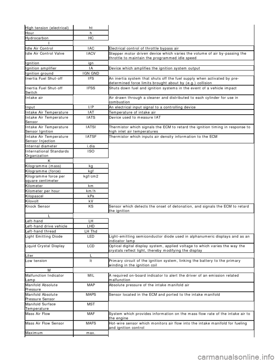
High
tension (electrical)
ht
Hourh
Hydro
carbon
HC
I
Idl
e Air Control
IACEl
ectrical control of throttle bypass air
Idl
e Air Control Valve
IACVStepper motor dri
ven device which vari
es the volume of air by-passing the
throttle to maintain the programmed idle speed
Ignitionign
Ignition am
plifier
IAD
evice which amplifies the i
gniti
on system output
Ignition groundIGN GND
In
ertia Fuel Shut-off
IFSAn
inertia system that shuts off the fuel supply when activated by pre-
determined force limits brough t about by (e.g.) collision
In
ertia Fuel Shut-off
Switch
IFSSShut
s down fuel and ignition systems in the event of a vehicle impact
Inta
ke air
Air drawn t
hrough a cleaner and distri
buted to each cylinder for use in
combustion
InputI/PAn
electrical input signal to a controlling device
Inta
ke Air Temperature
IATTem
perature of intake air
Inta
ke Air Temperature
Sensor
IATSDe
vice used to measure IAT
Inta
ke Air Temperature
Sensor Ignition
IATSITherm
istor which signals the ECM to retard
the ignition timing in response to
high inlet air temperatures
Inta
ke Air Temperature
Sensor Injection
IATSFTher
mistor which inputs air density information to the ECM
Internal diameteri.
dia
Inte
rnational Standards
Organization
ISO
K
Kilogramme (mass)kg
Kilogram
me (force)
kg
f
Ki
logramme force per
square centimeter
kg
f/cm2
Kilom
eter
km
Ki
lometer per hour
km
/h
Kilopasc
al
kP
a
KilovoltkV
Knock
Sensor
KSSens
or which detects the onset of detonation, and signals the ECM to retard
the ignition
L
Le
ft-hand
LH
Left-hand drive veh
icle
LHD
Le
ft-hand thread
LH Thd
Ligh
t Emitting Diode
LEDLigh
t-emitting semiconductor diode used
in alphanumeric displays and as an
indicator lamp
Liqu
id Crystal Display
LCDOp
tical digital display system, applied voltage to which varies the way the
crystals reflect light, thereby modifying the display
LiterL
Low ten
sion
ltPrim
ary circuit of the ignition system, linking the battery to the primary
winding in the ignition coil
M
Malfu
nction Indicator
Lamp
MILA
required on-board indicator to aler
t the driver of an emission related
malfunction
Mani
fold Absolute
Pressure
MAPAbsolute pressure o
f the intake manifold air
Mani
fold Absolute
Pressure Sensor
MAPSSensor loca
ted in the ECM and
ported to the intake manifold
Manifol
d Surface
Temperature
MST
Mass Ai
r Flow
MAFSy
stem which provides inform
ation on the mass flow rate of the intake air to
the engine
Mass Ai
r Flow Sensor
MAFSHot-wi
re sensor which monitors air flow
into the intake manifold for fueling
and ignition control
Maxim
um
max.
Page 54 of 2490
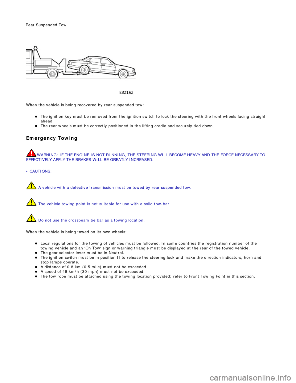
Wh en t
he vehicle is being reco
vered by rear suspended tow:
The ignition key must be remo ved from the ig
nition switch to lock the stee
ring with the front wheels facing straight
ahead.
The re ar
wheels must be
correctly positioned in the lifting cradle and securely tied down.
Em
ergency Towing
WARNING: IF THE
ENGINE IS NOT
RUNNING, THE STEERING WILL BECOME HEAVY AND THE FORCE NECESSARY TO
EFFECTIVELY APPLY THE BRAKES WILL BE GREATLY INCREASED.
• CAUTIONS:
A vehicle with a defective transmission must be towed by rear suspended tow.
The vehicle towing point is not suit able for use with a solid tow-bar.
Do not use the crossbeam tie bar as a towing location.
When the vehicle is being towed on its own wheels:
Loc a
l regulations for the towing of ve
hicles must be followed. In some co untries the registration number of the
towing vehicle and an 'On Tow' sign or warning triangle must be displayed at the rear of the towed vehicle.
The gear s
elector lever
must be in Neutral.
The
ignition switch must be in positi
on II to release the steering lock and make the direction indicators, horn and
stop lamps operate.
A di
stance of 0.8 km (0.5 mi
le) must not be exceeded.
A spe
ed of 48 km/h (30 mph) must not be exceeded.
The tow rope must be attached using th
e towi
ng location provided; refer to Front Towing Point in this section.
Rear Su
spended
Tow
Page 276 of 2490
Is hard-wi
red to the instrume
nt cluster message center.
Is hard
-wired to the J1962 diagnostic connector.
Op
era
tion
Th
e
system selects the soft or
firm damper setting according to the current ro ad and driving conditions, to optimise vehicle
ride and handling.
With the vehicle stationary, the dampers are in the firm setting, but will normally switch to the soft setting when the vehicle
exceeds 8 km/h (5 mile/h); all dampers are switched simultaneously.
Sudden movement of the vehicle body, in response to road inputs, is detected by the vertical accelerometers, and the ADCM
switches the dampers to the firm setting to give improved damping of the resultant oscillations.
When cornering forces are detected by th e lateral accelerometer, the ADCM switches the dampers to the firm setting to
reduce the roll rate an d improve wheel control.
After the event has passed, the dampers revert to the soft setting.
When the footbrake is applied, the ADCM re ceives a signal and calculates the rate of vehicle deceleration. If the deceleration
rate is greater than a certain threshold, the dampers are switched to the firm setting to reduce the pitch rate and improve
wheel control.
If a system failure occurs, the ADCM grounds the output line to the instrument cluster message center, which displays a
text warning SUSPENSION FAULT and illuminates the amber warning lamp. Under fault conditions the system always fails to
the firm setting, so that the vehicle will be safe to drive un der all road and driving conditions.
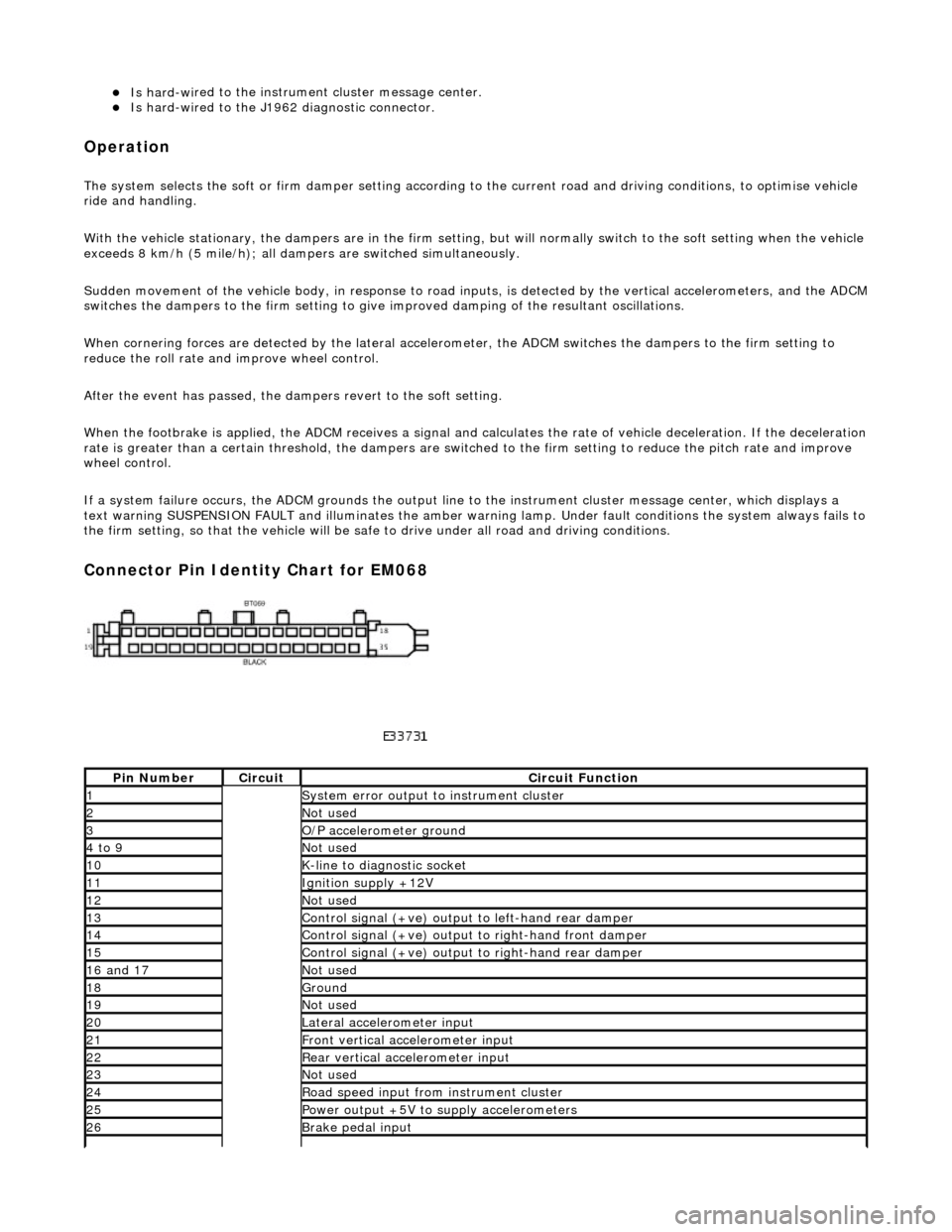
Connector Pin Identity Chart for EM068
Pin
Number
Ci
rcui
t
Circuit Functi
on
1System erro
r output to instrument
cluster
2Not
used
3O/
P a
ccelerometer ground
4 to
9
Not
used
10K-
li
ne to diagnostic socket
11Ignition su
pply +12V
12Not
used
13Control signal (+ve) output
to l
eft-hand rear damper
14Control signal (+ve) output
to right-hand front damp
er
15Control signal (+ve) output
to right-hand rear
damper
16
a
nd 17
No
t
used
18Ground
19No
t
used
20Lateral
accelerometer i
nput
21Front vertical ac
celerometer in
put
22Rear vertical
acce
lerometer input
23No
t
used
24R
o
ad speed input from
instrument cluster
25Power output +5V to suppl y accelerometers
26Brake peda
l input
Page 315 of 2490
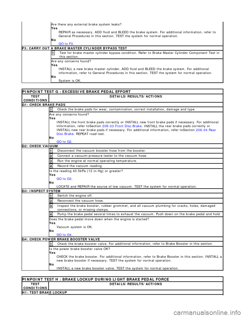
Are th
ere any external brake system leaks?
Yes REPAIR as necessary. ADD fluid and BLEED the brak e system. For additional information, refer to
General Procedures in this section. TEST the system for normal operation.
No GO to F3
.
F
3: CARRY OUT A BRAKE MASTER CYLINDER BYPASS TEST
Te
st for brake master cylinder bypass condition. Re
fer to Brake Master Cylinder Component Test in
this section.
1
A
re any concerns found?
Yes INSTALL a new brake master cylinder, ADD flui d and BLEED the brake system. For additional
information, refer to General Proc edures in this section. TEST the system for normal operation.
No System is OK.
PINPO
INT TEST G : EXCESSIVE BRAKE PEDAL EFFORT
TE
ST
CONDITIONS
D
ETAILS/RESULTS/ACTIONS
G1
: CHECK BRAKE PADS
Check the brake pads for wear, contamin
atio
n, correct installation, damage and type.
1
A
re any concerns found?
Yes INSTALL the front brake pads correctly or INSTALL ne w front brake pads if necessary. For additional
information, refer toSection 206
-03
Front Disc Brake
. INSTALL the
rear brake pads correctly or
INSTALL new rear brake pads if necessary. For additional information, refer toSection 206
-04
Rear
Di
sc Brake
. REPEAT road test.
No
GO to G2
.
G2:
CHECK VACUUM
Di
sconnect the vacuum booster hose from the booster.
1
Conne
ct a vacuum/pressure tester to the vacuum hose.
2
Ru
n the engine at normal operating temperature.
3
Re
cord the vacuum reading.
4
Is
the reading 40.5kPa (1
2 in-Hg) or greater?
Yes GO to G3
.
No
LOCATE and REPAIR the source of low vacuum . TEST the system for normal operation.
G3
: INSPECT SYSTEM
Swi
tch the engine off.
1
Re
connect the vacuum hose.
2
Inspect th
e brake booster, rubber grommet, and al
l vacuum plumbing for cracks, holes, damaged
connections, or missing clamps.
3
Pump th
e brake pedal several time
s to exhaust the vacuum. Push down on the brake pedal and hold.
4
Does th
e brake pedal move down
when the engine is started?
Yes Vacuum system is OK.
No GO to G4
.
G4
: CHECK POWER BRAKE BOOSTER VALVE
Check the brake booster valve. For
add
itional information, refer to
Brake Booster in this section.
1
Is th
e power brake booster valve OK?
Yes CHECK the brake booster. Fo r additional information, refer to Brak e Booster in this section. INSTALL a
new brake booster if necessary. TEST the system for normal operation.
No INSTALL a new brake booster valve. TEST the system for normal operation.
P
INPOINT TEST H : BRAKE LOCKUP
DURING LIGHT BRAKE PEDAL FORCE
TE
ST
CONDITIONS
D
ETAILS/RESULTS/ACTIONS
H1
: TEST BRAKE LOCKUP
Page 318 of 2490
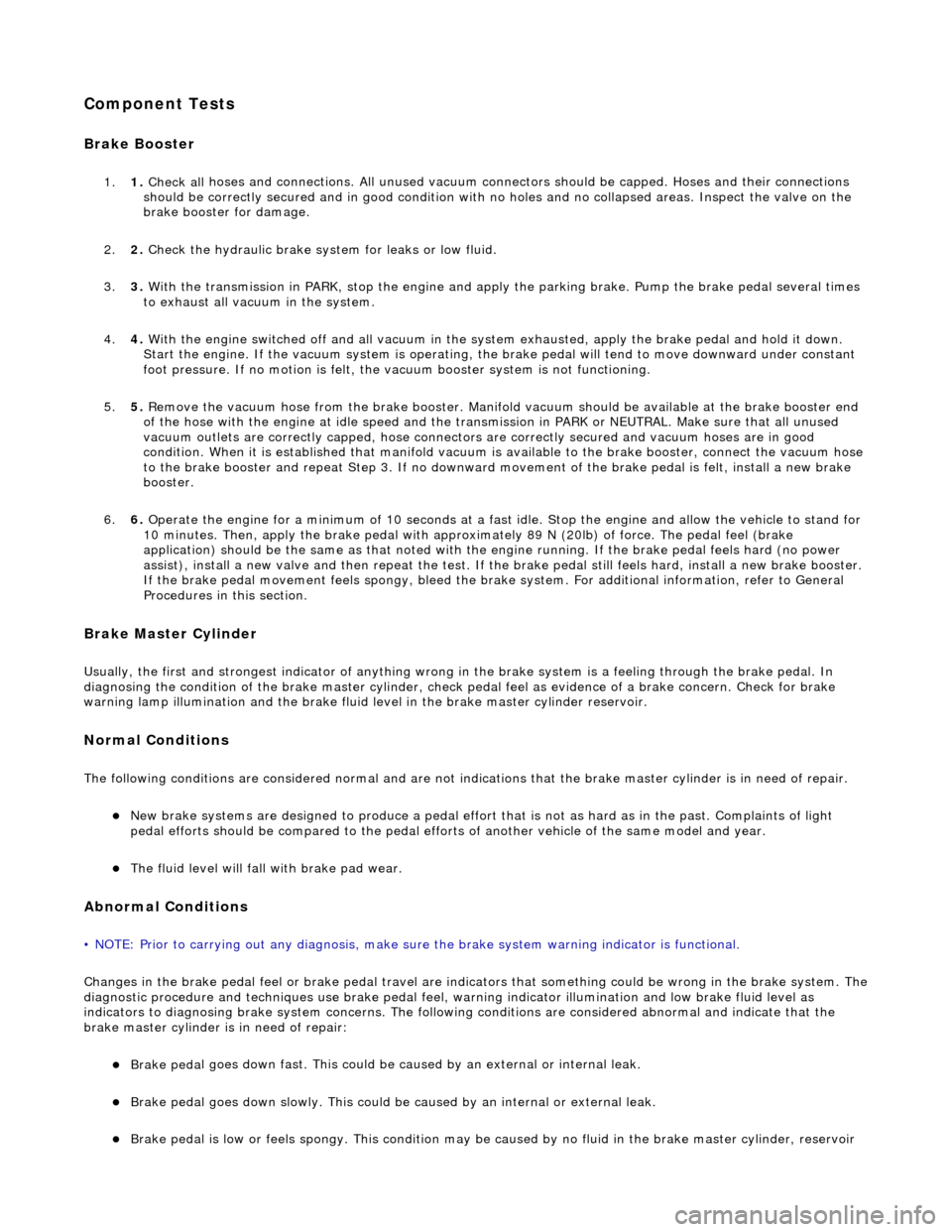
Comp
onent Tests
Bra
k
e Booster
1.
1. Chec k all
hoses and connections. All unused vacuum connectors should be capped. Hoses and their connections
should be correctly secured and in good condition with no holes and no collapsed areas. Inspect the valve on the
brake booster for damage.
2. 2. Check the hydraulic brake system for leaks or low fluid.
3. 3. With the transmission in PARK, stop the engine and apply the parking brake. Pump the brake pedal several times
to exhaust all vacuum in the system.
4. 4. With the engine switched off and all vacuum in the system exhausted, appl y the brake pedal and hold it down.
Start the engine. If the vacuum system is operating, the brake pedal will tend to move downward under constant
foot pressure. If no motion is felt, the vacuum booster system is not functioning.
5. 5. Remove the vacuum hose from the brake booster. Manifold vacuum should be available at the brake booster end
of the hose with the engine at idle speed and the transm ission in PARK or NEUTRAL. Make sure that all unused
vacuum outlets are correctly capped, hose connectors are correctly secured and vacuum hoses are in good
condition. When it is established that manifold vacuum is available to the brake booster, connect the vacuum hose
to the brake booster and repeat Step 3. If no downward movement of the brake pedal is felt, install a new brake
booster.
6. 6. Operate the engine for a minimum of 10 seconds at a fast idle. Stop the engine and allow the vehicle to stand for
10 minutes. Then, apply th e brake pedal with approximately 89 N ( 20lb) of force. The pedal feel (brake
application) should be the same as that noted with the engine running. If the brake pedal feels hard (no power
assist), install a new valve and then re peat the test. If the brake pedal still feels hard, in stall a new brake booster.
If the brake pedal movement feels spongy, bleed the brak e system. For additional information, refer to General
Procedures in this section.
Bra k
e Master Cylinder
Usual
l
y, the first and strongest
indicator of anything wrong in the brake syst em is a feeling through the brake pedal. In
diagnosing the condition of the brake master cylinder, check pedal feel as evidence of a brake concern. Check for brake
warning lamp illumination and the brake fluid le vel in the brake master cylinder reservoir.
Normal Conditio
ns
The fo
llowing conditions are considered norm
al and are not indications that the brake master cylinder is in need of repair.
New bra
ke systems are designed to produc
e a pedal effort that is not as hard as in the past. Complaints of light
pedal efforts should be compared to the pedal effort s of another vehicle of the same model and year.
The fl
uid level will fall with brake pad wear.
Abnormal Conditions
•
NOTE: Prior to carrying out any diag
nosis, make sure the brake system warning indicator is functional.
Changes in the brake pedal feel or brake pedal travel are in dicators that something could be wrong in the brake system. The
diagnostic procedure and techniques use brake pedal feel, warning indicator illu mination and low brake fluid level as
indicators to diagnosing brake system co ncerns. The following conditions are cons idered abnormal and indicate that the
brake master cylinder is in need of repair:
Brake ped a
l goes down fast. Th
is could be caused by an ex ternal or internal leak.
Brake pedal goes down slowly
. This could be
caused by an internal or external leak.
Brak
e pedal is low or feels spongy. This condition may be ca
used by no fluid in the brake master cylinder, reservoir