SOLENOID JAGUAR X308 1998 2.G Owner's Manual
[x] Cancel search | Manufacturer: JAGUAR, Model Year: 1998, Model line: X308, Model: JAGUAR X308 1998 2.GPages: 2490, PDF Size: 69.81 MB
Page 536 of 2490
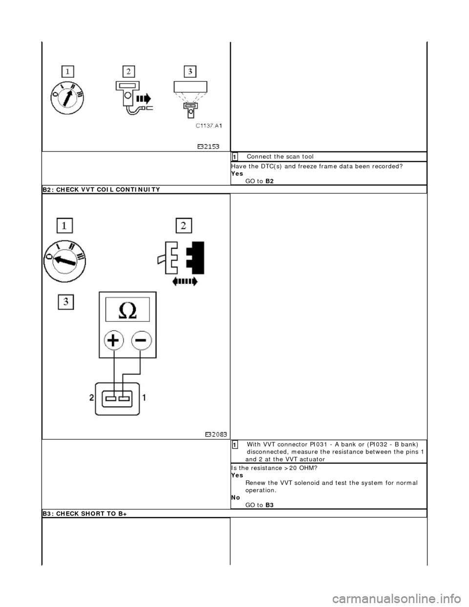
Connect
the scan tool
1
Have the DTC(s) and fr
eeze f
rame data been recorded?
Yes GO to B2
B2 : CH
ECK VVT COIL CONTINUITY
W
i
th VVT connector PI031 - A bank or (PI032 - B bank)
disconnected, measure the resistance between the pins 1
and 2 at the VVT actuator
1
I s
the resistance >20 OHM?
Yes Renew the VVT solenoid and te st the system for normal
operation.
No GO to B3
B3: CHECK
SHORT TO B+
Page 537 of 2490
R
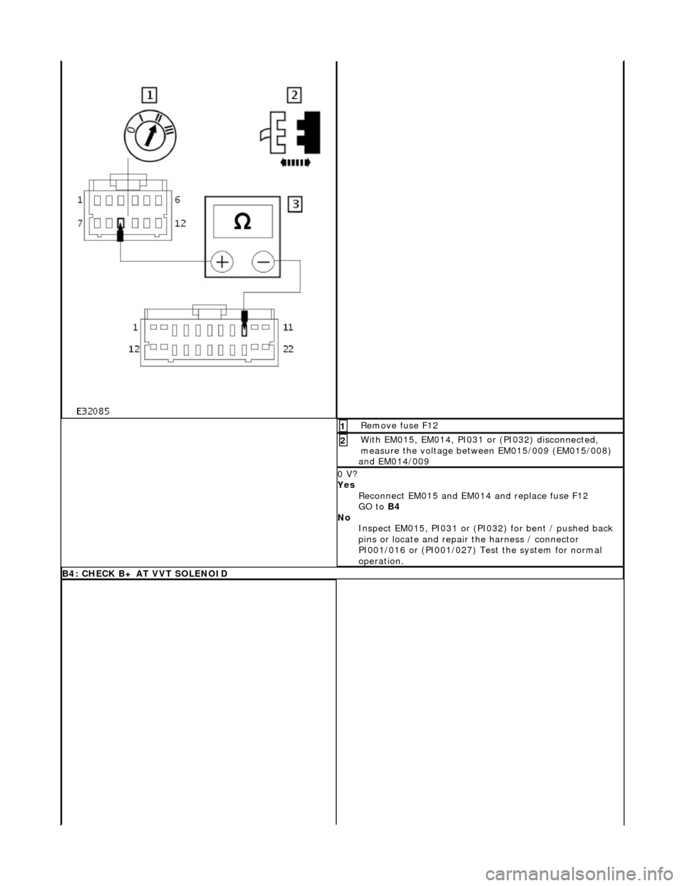
emove fuse F12
1
W
ith EM015, EM014, PI031 or (PI032) disconnected,
measure the voltage between EM015/009 (EM015/008)
and EM014/009
2
0 V?
Yes Reconnect EM015 and EM0 14 and replace fuse F12
GO to B4
No Inspect EM015, PI031 or (PI032) for bent / pushed back
pins or locate and repair the harness / connector
PI001/016 or (PI001/027) Test the system for normal
operation.
B4
: CHECK B+ AT VVT SOLENOID
Page 540 of 2490
Pinpoint test C: P1396
VVT solenoid malfunction
W
i
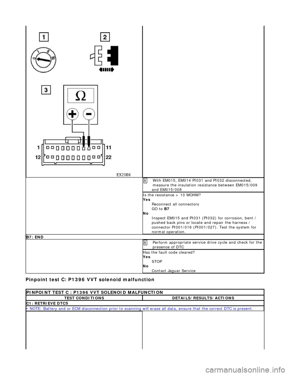
th EM015, EM014 PI031 and PI032 disconnected,
measure the insulation resistance between EM015/009
and EM015/008
1
I s
the resistance > 10 MOHM?
Yes Reconnect all connectors
GO to B7
No Inspect EM015 and PI031 (PI032) for corrosion, bent /
pushed back pins or locate and repair the harness /
connector PI001/016 (PI001/027). Test the system for
normal operation.
B7: EN
D
Perform
a
ppropriate service drive cycle and check for the
presence of DTC
1
Has th
e fault code cleared?
Yes STOP
No Contact Jaguar Service
PINPOINT TES
T C : P1396 VVT SOLENOID MALFUNCTION
T
E
ST CONDITIONS
D
E
TAILS/RESULTS/ACTIONS
C1
: RETRIEVE DTC
S
•
NOTE
: Battery and or ECM disconnection prior to scanning wi
ll erase all data, ensure that the correct DTC is present.
Page 541 of 2490
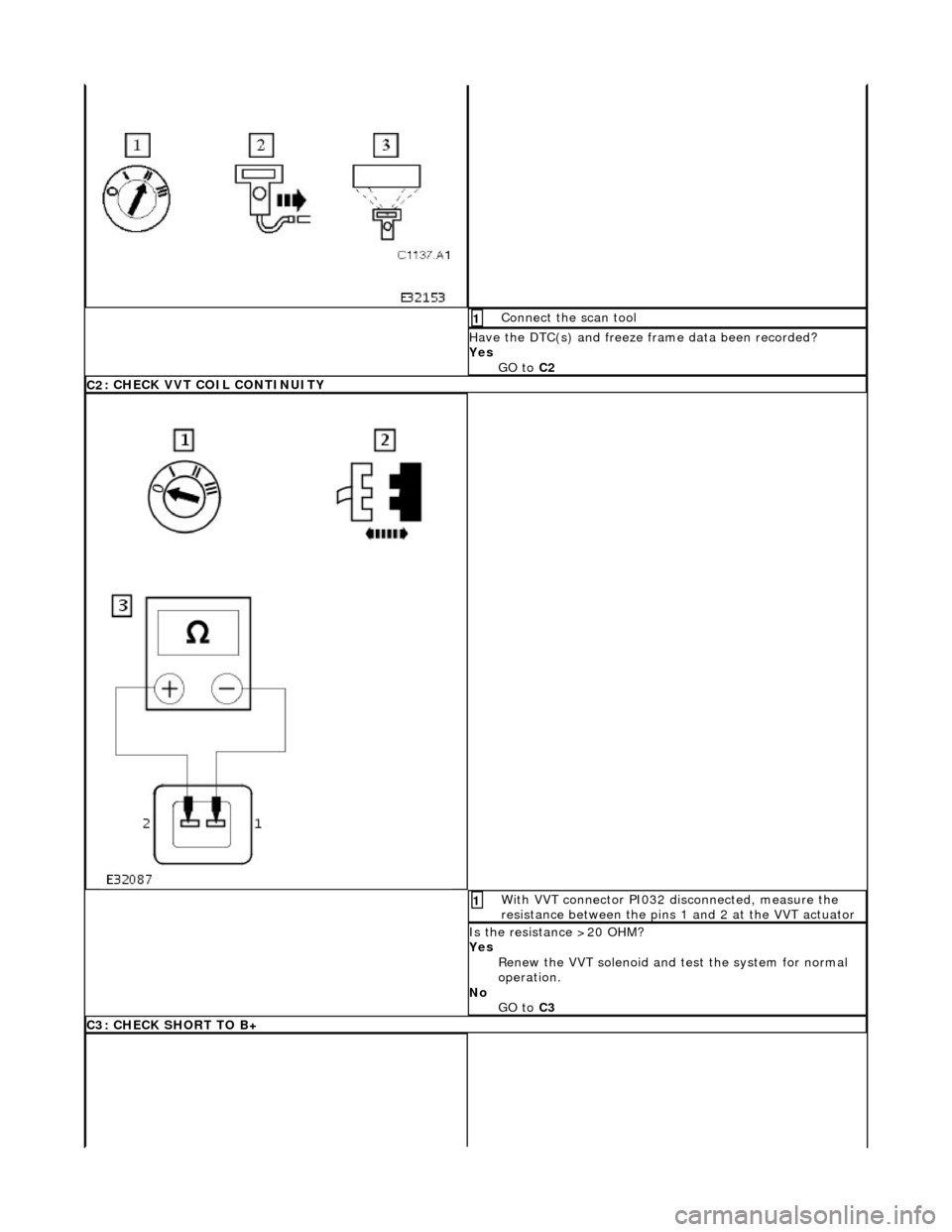
Conne
ct the scan tool
1
Have the DTC(s) and fr
eeze
frame data been recorded?
Yes GO to C2
C2
: CHECK VVT COIL CONTINUITY
Wi
th VVT connector PI032 disconnected, measure the
resistance between the pins 1 and 2 at the VVT actuator
1
I
s the resistance >20 OHM?
Yes Renew the VVT solenoid and te st the system for normal
operation.
No GO to C3
C3
: CHECK SHORT TO B+
Page 542 of 2490
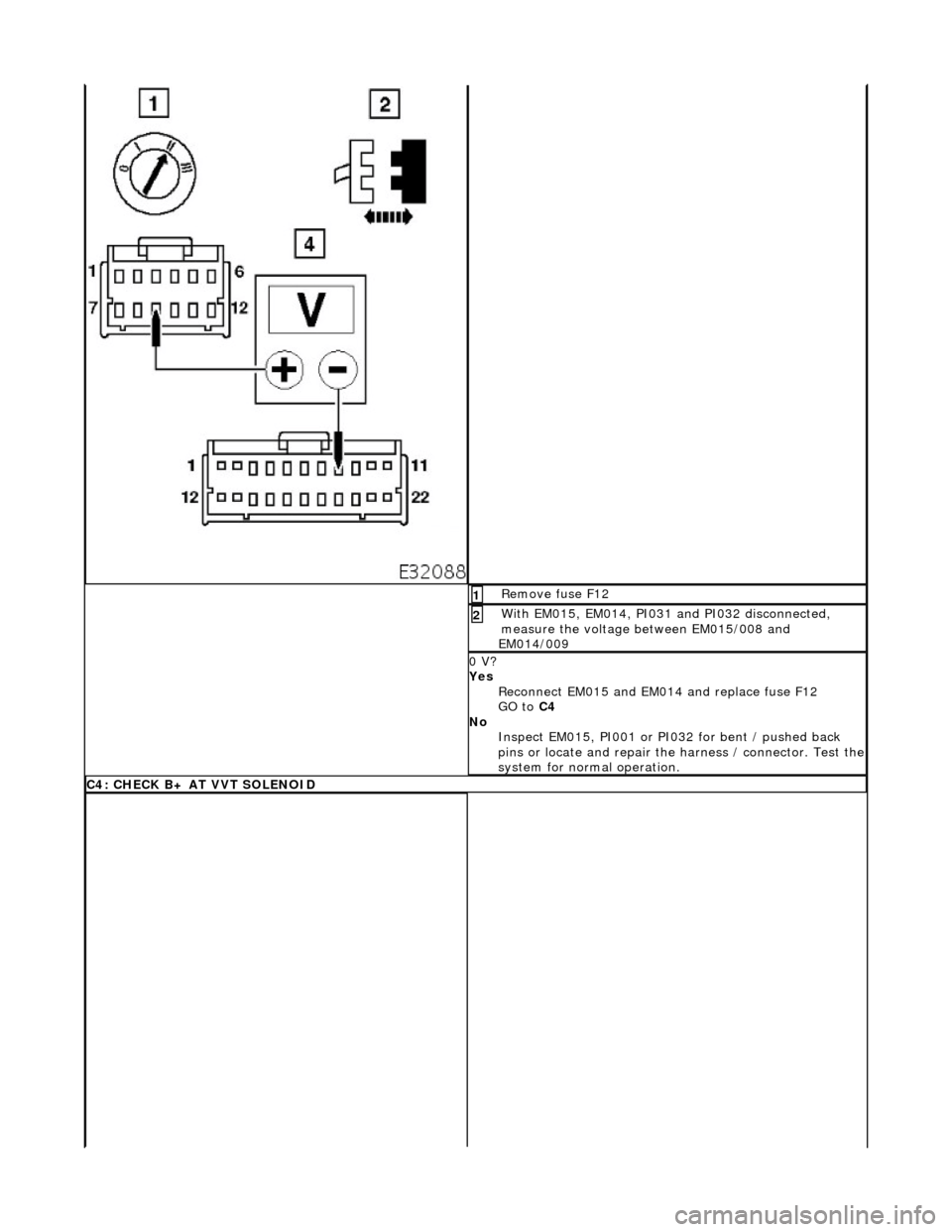
Re
move fuse F12
1
W
i
th EM015, EM014, PI031 and PI032 disconnected,
measure the voltage between EM015/008 and
EM014/009
2
0 V?
Yes
Reconnect EM015 and EM0 14 and replace fuse F12
GO to C4
No Inspect EM015, PI001 or PI032 for bent / pushed back
pins or locate and repair the harness / connector. Test the
system for normal operation.
C4 :
CHECK B+ AT VVT SOLENOID
Page 644 of 2490
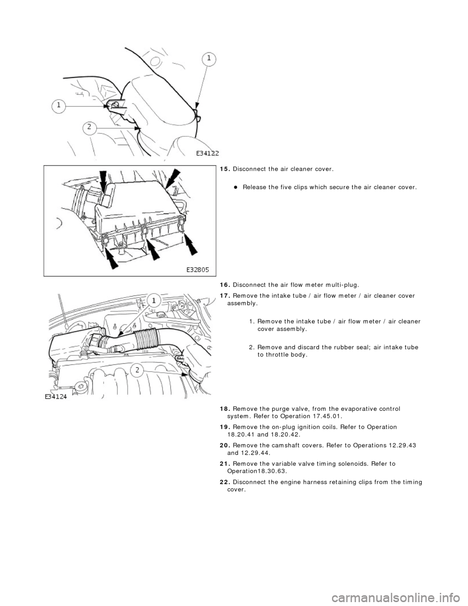
15. Di
sconnect the air cleaner cover.
R
e
lease the five clips which se
cure the air cleaner cover.
16. Disconnect the air flow meter multi-plug.
17 . R
emove the intake tube / air
flow meter / air cleaner cover
assembly.
1. Remove the intake tube / air flow meter / air cleaner
cover assembly.
2. Remove and discard the ru bber seal; air intake tube
to throttle body.
18. Remove the purge valve, fro m the evaporative control
system. Refer to Operation 17.45.01.
19. Remove the on-plug ignition coils. Refer to Operation
18.20.41 and 18.20.42.
20. Remove the camshaft covers. Refer to Operations 12.29.43
and 12.29.44.
21. Remove the variable valve ti ming solenoids. Refer to
Operation18.30.63.
22. Disconnect the engine harness retaining clips from the timing
cover.
Page 648 of 2490
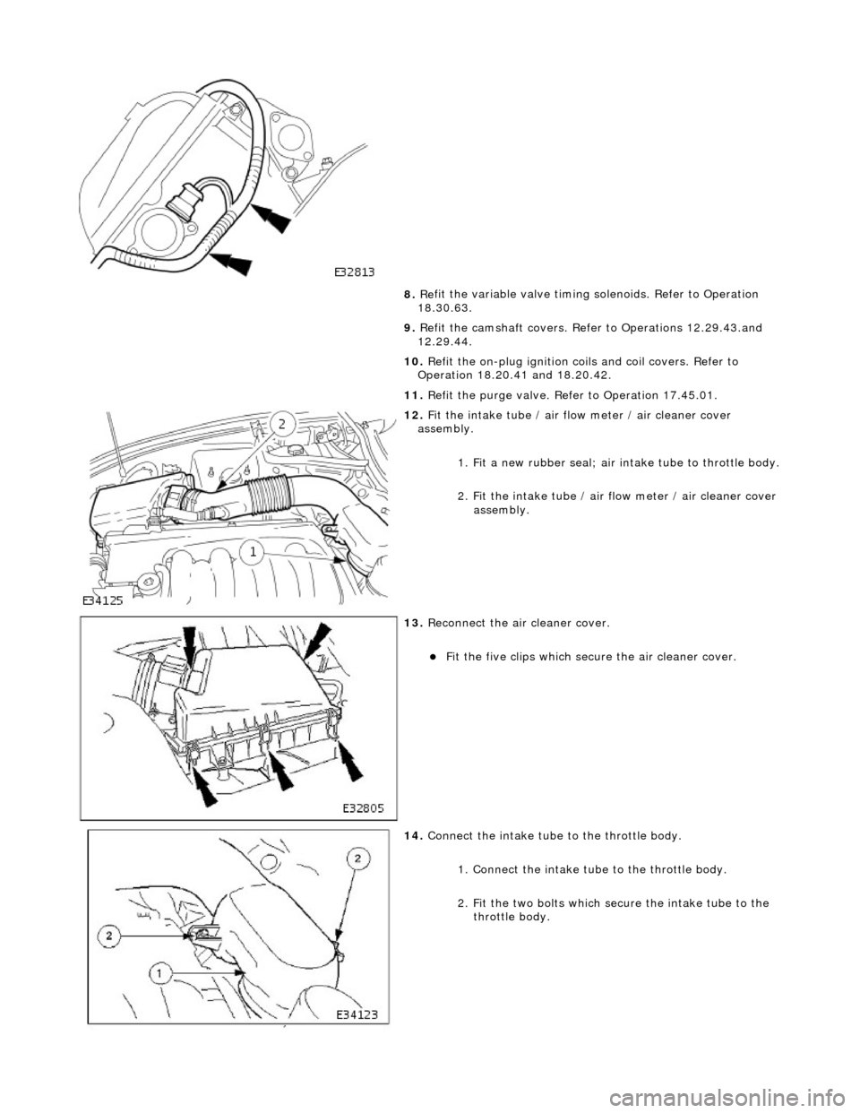
8. Re
fit the variable valve timing
solenoids. Refer to Operation
18.30.63.
9. Refit the camshaft covers. Refer to Operations 12.29.43.and
12.29.44.
10. Refit the on-plug ignition coils and coil covers. Refer to
Operation 18.20.41 and 18.20.42.
11. Refit the purge valve. Refer to Operation 17.45.01.
12 . F
it the intake tube / air flow meter / air cleaner cover
assembly.
1. Fit a new rubber seal; air in take tube to throttle body.
2.
Fit the intake tube / air
flow meter / air cleaner cover
assembly.
13 . R
econnect the air cleaner cover.
F
it
the five clips which secu
re the air cleaner cover.
14. Co
nnect the intake tube to the throttle body.
1. Connect the intake tube to the throttle body.
2. Fit the two bolts which secure the intake tube to the throttle body.
Page 653 of 2490
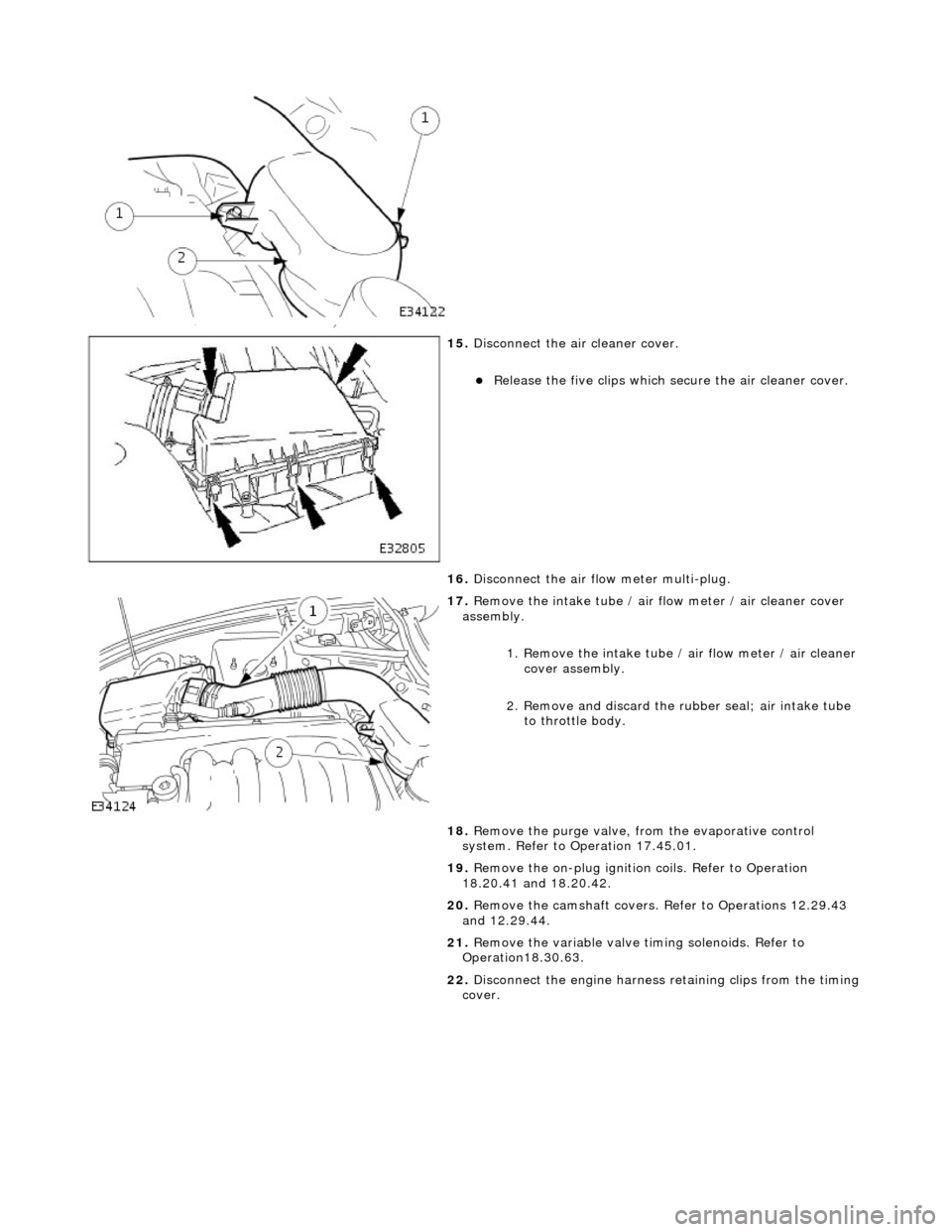
15
.
Disconnect the air cleaner cover.
R
elease the five clips which se
cure the air cleaner cover.
16. Disconnect the air flow meter multi-plug.
17
.
Remove the intake tube / air flow meter / air cleaner cover
assembly.
1. Remove the intake tube / air flow meter / air cleaner
cover assembly.
2. Remove and discard the ru bber seal; air intake tube
to throttle body.
18. Remove the purge valve, fro m the evaporative control
system. Refer to Operation 17.45.01.
19. Remove the on-plug ignition coils. Refer to Operation
18.20.41 and 18.20.42.
20. Remove the camshaft covers. Refer to Operations 12.29.43
and 12.29.44.
21. Remove the variable valve ti ming solenoids. Refer to
Operation18.30.63.
22. Disconnect the engine harness retaining clips from the timing
cover.
Page 657 of 2490
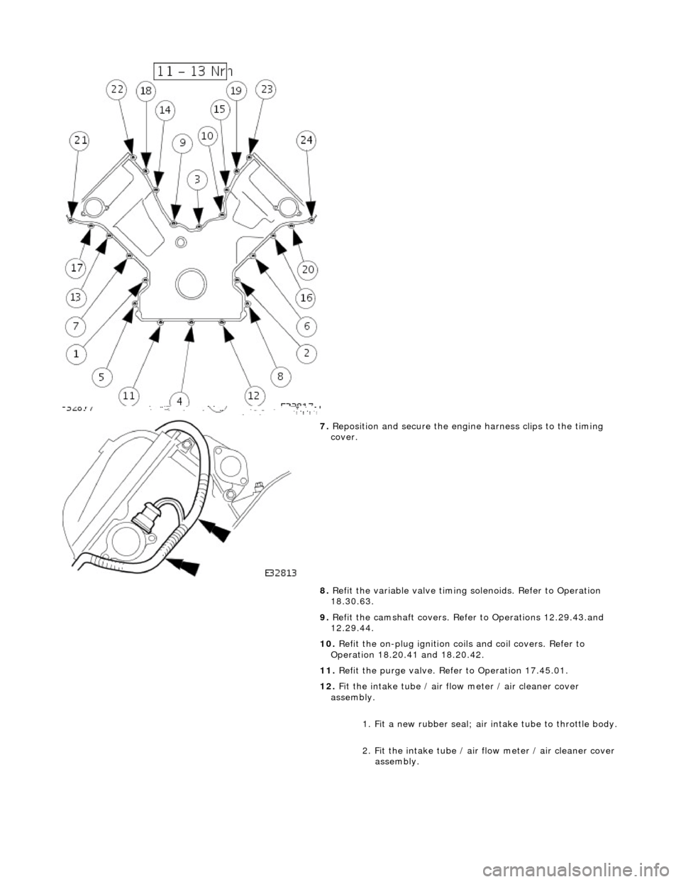
7. Reposition and secure the engine harness clips to the timing
cover.
8. Refit the variable valve timing solenoids. Refer to Operation
18.30.63.
9. Refit the camshaft covers. Refer to Operations 12.29.43.and
12.29.44.
10. Refit the on-plug ignition coils and coil covers. Refer to
Operation 18.20.41 and 18.20.42.
11. Refit the purge valve. Refer to Operation 17.45.01.
12. Fit the intake tube / air flow meter / air cleaner cover
assembly.
1. Fit a new rubber seal; air in take tube to throttle body.
2. Fit the intake tube / air flow meter / air cleaner cover
assembly.
Page 1015 of 2490
Fuel D
istribution
Fuel is supplied to th
e engine
via eight fuel injectors (one pe r cylinder). The injectors are located in two fuel rails which r un
the length of each cylinder bank and ar e integral with the air intake manifold.
Fuel pumped from the tank enters a feed pipe at the rear of bank 2. Fuel flow is along bank 2 fuel rail, across the top front
of the engine (cross-over pipe) and through bank 1 fuel rail, the unused fuel re turning to the tank via a pressure regulator.
The fuel injectors are each controlled electrically from the engine control module (ECM).
A test valve is fitted to the cross-over pipe connecting the fu el rails at the front of the intake manifold. This valve allows the
fuel system to be depr essurized during servicin g and troubleshooting.
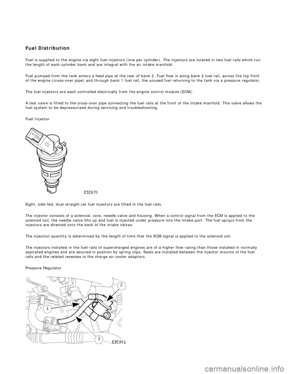
Fuel Injector
Eight, side-fed, dual straight-jet fuel injectors are fi tted in the fuel rails.
The injector consists of a solenoid, core, needle valve and ho using. When a control signal from the ECM is applied to the
solenoid coil, the needle valve lifts up and fuel is injected under pressure into the intake port. The fuel sprays from the
injectors are directed onto the back of the intake valves.
The injection quantity is determined by the length of time that the ECM signal is applied to the solenoid coil.
The injectors installed in the fuel rails of supercharged engines are of a higher flow rating than those installed in normally
aspirated engines and are secured in position by spring clips. Seals are instal led between the injector mounts of the fuel
rails and the related re cesses in the charge air cooler adaptors.
Pressure Regulator