SOLENOID JAGUAR X308 1998 2.G User Guide
[x] Cancel search | Manufacturer: JAGUAR, Model Year: 1998, Model line: X308, Model: JAGUAR X308 1998 2.GPages: 2490, PDF Size: 69.81 MB
Page 455 of 2490
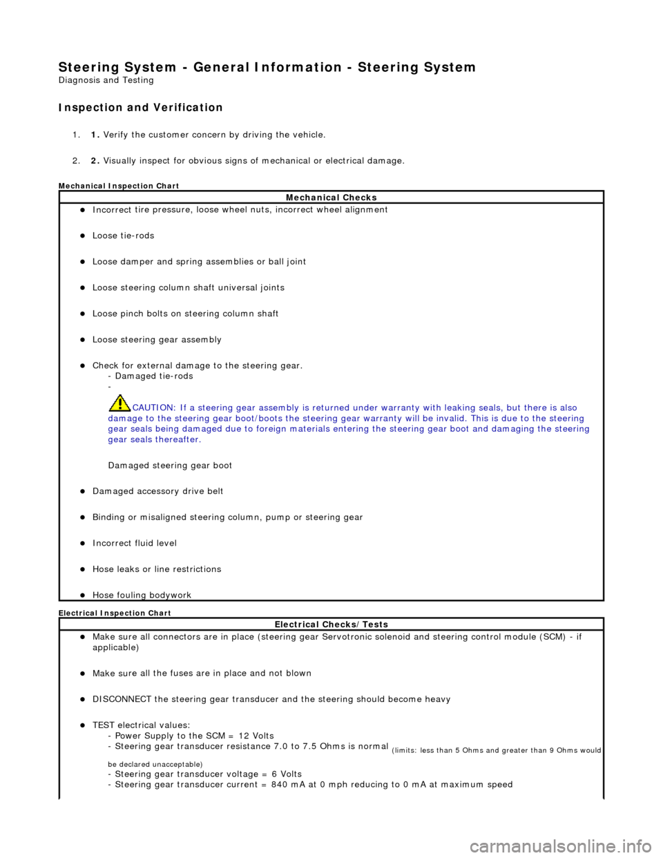
Steering System - General Inform
ation - Steering System
D
iagnosis and Testing
I
nspection and Verification
1.
1. Verify t
he customer concern by driving the vehicle.
2. 2. Visually inspect for obvious signs of mechanical or electrical damage.
Mec
hanical Inspection Chart
Electrical Inspection Chart
Mechanical Checks
Incorrect
tire pressure, loose whee
l nuts, incorrect wheel alignment
Loose ti
e-rods
Loose dam
per and spring assemblies or ball joint
Loose s
teering column shaft universal joints
Loose pinc
h bolts on steering column shaft
Loose steeri
ng gear assembly
Check f
or external damage to the steering gear.
- Damaged tie-rods
-
CAUTION: If a steering gear assemb ly is returned under warranty with leaking seals, but there is also
damage to the steering gear boot/boots the steering gear warranty will be invalid. This is due to the steering
gear seals being damaged due to fore ign materials entering the steering gear boot and damaging the steering
gear seals thereafter.
Damaged steering gear boot
Damaged accessory driv
e belt
Bin
ding or misaligned steering co
lumn, pump or steering gear
Incorrect fluid
level
Hose leaks o
r line restrictions
Hose fou
ling bodywork
El
ectrical Checks/Tests
Make sure all
connectors are in plac
e (steering gear Servotronic solenoid and steering control module (SCM) - if
applicable)
Make su
re all the fuses are in place and not blown
D
ISCONNECT the steering gear transducer
and the steering should become heavy
TEST e
lectrical values:
- Power Supply to the SCM = 12 Volts
- Steering gear transducer resist ance 7.0 to 7.5 Ohms is normal
(
limits: less than 5 Ohms and greater than 9 Ohms would
be declared unacceptable)
- Steeri
ng gear transducer voltage = 6 Volts
- Steering gear transducer cu rrent = 840 mA at 0 mph reducing to 0 mA at maximum speed
Page 488 of 2490
The rotary distri
butor and control sleeve turn relative to ea
ch other, forming the unequal restrictions which create the
differential pressures to operat e the rack piston; the displacement of the di stributor and sleeve being controlled by the
elastic deformation of a torsion bar which is concentric with the pinion and valve. Refer to Positive Center-Feel Torsion Bar
in this sub-sectio n.
The hydraulic reaction piston moves axially, relative to th e rotary distributor, and is connected to the control sleeve by a
three-bearing helical screw. Pressure applied either side of the hydraulic reaction piston is translated into a rotational force
which increases steering effort. For detail s of Servotronic speed-sensitive steering control, refer to Servotronic Control in
this sub-section.
When the vehicle is travelling straight ah ead, the valve restrictions are balanced, thus providing equal pressures on either
side of the rack piston. When load is a pplied at the steering wheel, the two halves of the control valve (rotary distributor
and control sleeve) are displaced making the restrictions unequa l. The resulting differential pressures on either side of the
rack piston, assist the steering rack to mo ve to left or right. As the turning load is removed, the pressures equalize again
and the steering return s to the straight ahead position , aided by suspension geometry.
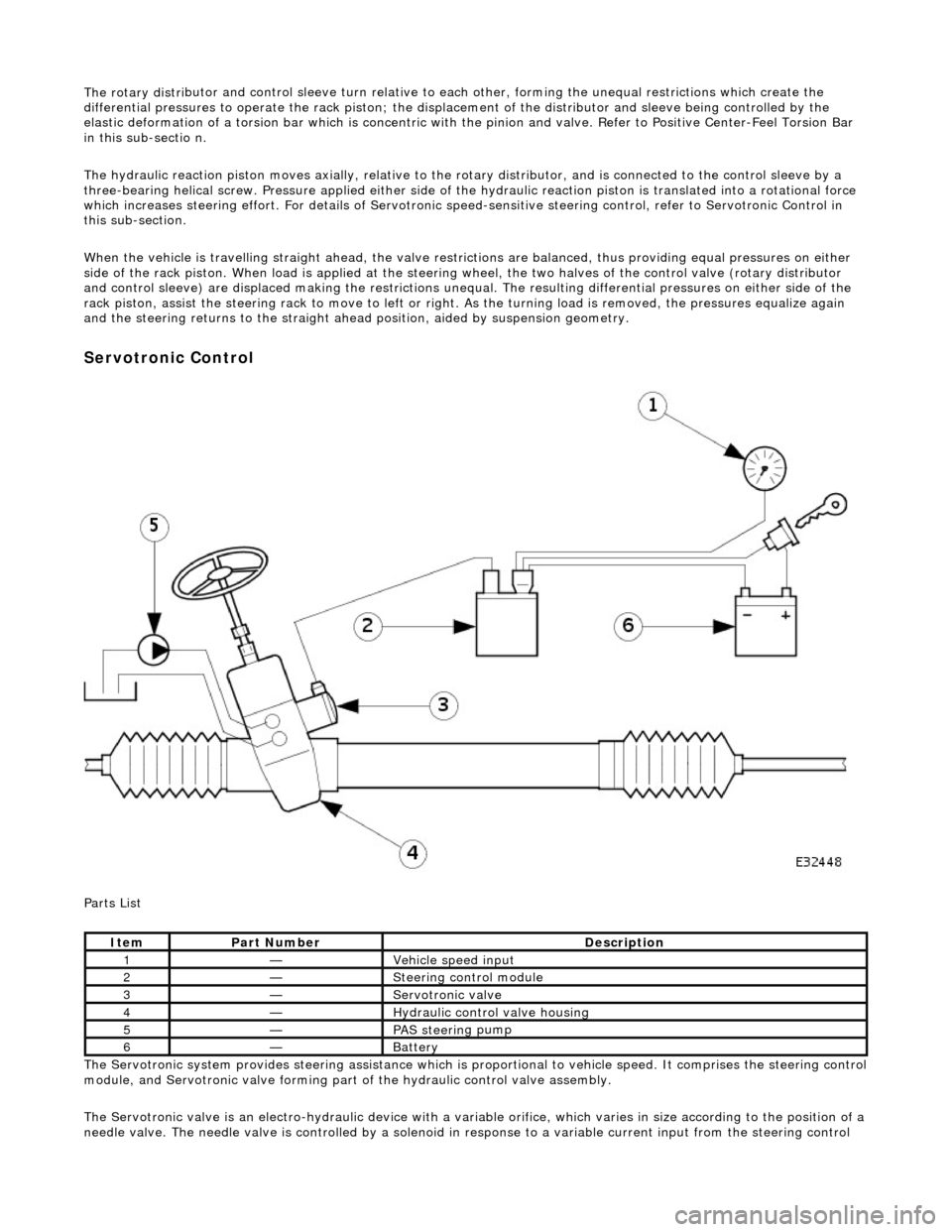
Serv
otronic Control
P a
rts List
The Servotronic system provides steering assistance which is pr oportional to vehicle speed. It comprises the steering control
module, and Servotronic valve forming part of the hydraulic control valve assembly.
The Servotronic valve is an electro-hydrauli c device with a variable orifice, which varies in size according to the position of a
needle valve. The needle valve is controlled by a solenoid in response to a variable current input from the steering control
Ite
m
Part
Number
Descr
iption
1—Vehi
cl
e speed input
2—Steeri
ng control
module
3—Servotronic valve
4—Hydraulic
control valve housing
5—PAS stee
rin
g pump
6—Batt
ery
Page 508 of 2490
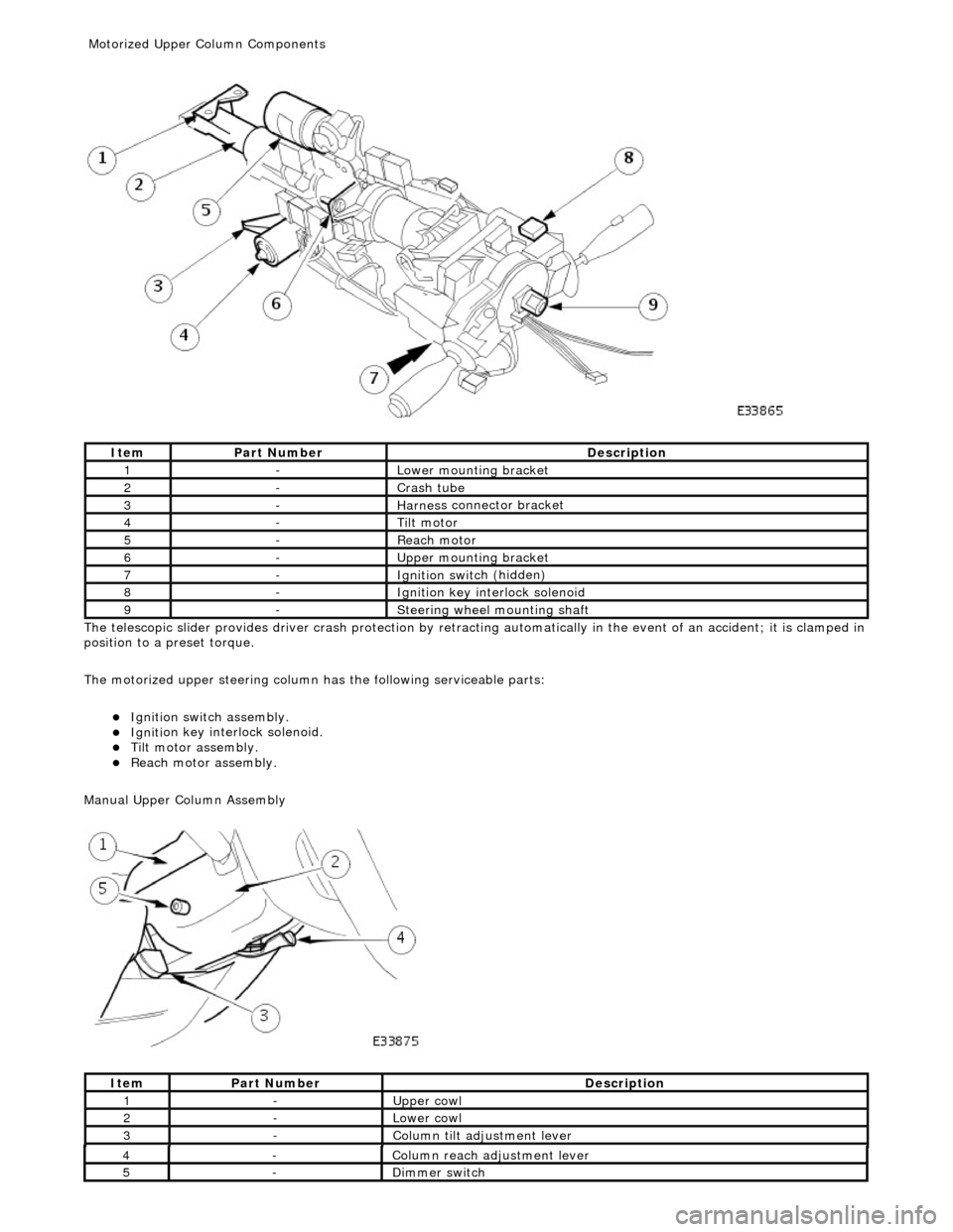
The te
lescopic slider provides driver crash
protection by retracting automatically in the event of an accident; it is clamped in
position to a preset torque.
The motorized upper steering column has the following serviceable parts:
Igniti
on switch assembly.
Igni
ti
on key interlock solenoid.
Ti
lt
motor assembly.
Reach motor assembly.
Manu al Upper Column Assembly
Ite
m
Par
t
Number
De
scr
iption
1-L
o
wer mounting bracket
2-Crash tube
3-Harnes
s c
onnector bracket
4-Tilt motor
5-Reach m
otor
6-Upper
moun
ting bracket
7-Ignition switc
h
(hidden)
8-Igni
ti
on key interlock solenoid
9-S
t
eering wheel mounting shaft
It
e
m
Par
t
Number
De
scr
iption
1-Upper
cowl
2-Lower cowl
3-Colu
mn tilt adjustment lever
4-Col
u
mn reach adjustment lever
5-Di
mm
er switch
Motorized Upper Co
lumn Components
Page 509 of 2490
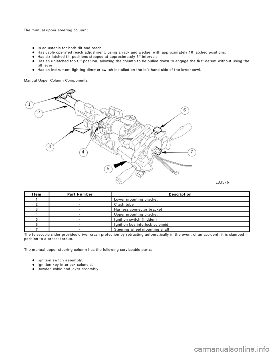
Is adjustable for both til
t and reach.
Has ca
ble operated reach adjustment, using a rack an
d wedge, with approximately 16 latched positions.
Has si
x latched tilt positions steppe
d at approximately 3° intervals.
Has an u
nlatched top tilt position, allowing the column to be
pulled down to engage the first detent without using the
tilt lever.
Has an instrument li
ghti
ng dimmer switch installed on the left-hand side of the lower cowl.
Manual Upper Column Components
The telescopic slider provides driver crash protection by retracting automatically in the event of an accident; it is clamped in
position to a preset torque.
The manual upper steering column has the following serviceable parts:
Igni
tion switch assembly.
Igni
tion key interlock solenoid.
Bowden
cable and lever assembly.
It
em
Par
t Number
De
scription
1-L
ower mounting bracket
2-Crash tube
3-Harnes
s connector bracket
4-Upper
mounting bracket
5-Ignition switc
h (hidden)
6-Igni
tion key interlock solenoid
7-S
teering wheel mounting shaft
The manu
al upper
steering column:
Page 527 of 2490
E
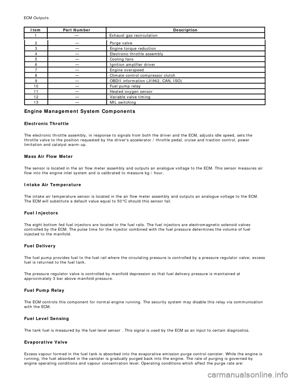
ngine Management System Components
Electronic Throt
tle
The
electronic throttle assembly, in resp
onse to signals from both the driver and the ECM, adjusts idle speed, sets the
throttle valve to the position requested by the driver's accelerator / throttle pedal, cruise and traction control, power
limitation and catalyst warm-up.
Mass
Air Flow Meter
The sensor i
s located in the air flow mete
r assembly and outputs an analogue voltag e to the ECM. This sensor measures air
flow into the engine inlet system and is calibrated to measure kg / hour.
In
take Air Temperature
Th
e intake air temperature sensor is loca
ted in the air flow meter assembly and outputs an analogue voltage to the ECM.
The ECM will substitute a default value eq ual to 50°C should this sensor fail.
Fuel Injectors
The eigh
t bottom fed fuel injectors are located in the fuel rails. Th
e fuel injectors are electromagnetic solenoid valves
controlled by the ECM. The pulse time for the injector combined with the fuel pr essure determines the volume of fuel
injected to the manifold.
Fue
l Delivery
The fu
el pump provides fuel to the fuel rail where the circulat
ing pressure is controlled by a pressure regulator valve; excess
fuel is returned to the fuel tank.
The pressure regulator valve is controlled by manifold depression so that fuel delivery pressure is maintained at
approximately 3 bar above manifold pressure.
Fuel Pump
Relay
The ECM controls thi
s component for normal
engine running. The security system may disable this relay via communication
with the ECM.
Fuel Lev
el Sensing
The tank fuel
is measured by the fuel le
vel sensor . This signal is used by the ECM as an in put to certain diagnostics.
Eva
porative Valve
Excess vapour
formed in the fuel tank is
absorbed into the evaporative emission pu rge control canister. While the engine is
running, the fuel absorbed in the canister is gradually purged back into the engine. The rate of purging is governed by
engine operating conditions and vapour concentration level. Operating conditions which affect the purge rate are:
2—Purge
valve
3—Engine
torque reduction
4—E
lectronic throttle assembly
5—Coo
ling fans
6—Ignition amplifier driver
7—Engine overspeed
8—Cli
mate control compressor clutch
9—O
BDII information (J1962, CAN, ISO)
10—F
uel pump relay
11—Heat
ed oxygen sensor
12—Vari
able valve timing
13—MIL sw
itching
ECM Out
puts
It
em
Par
t Number
De
scription
1—Exhaus
t gas recirculation
Page 528 of 2490
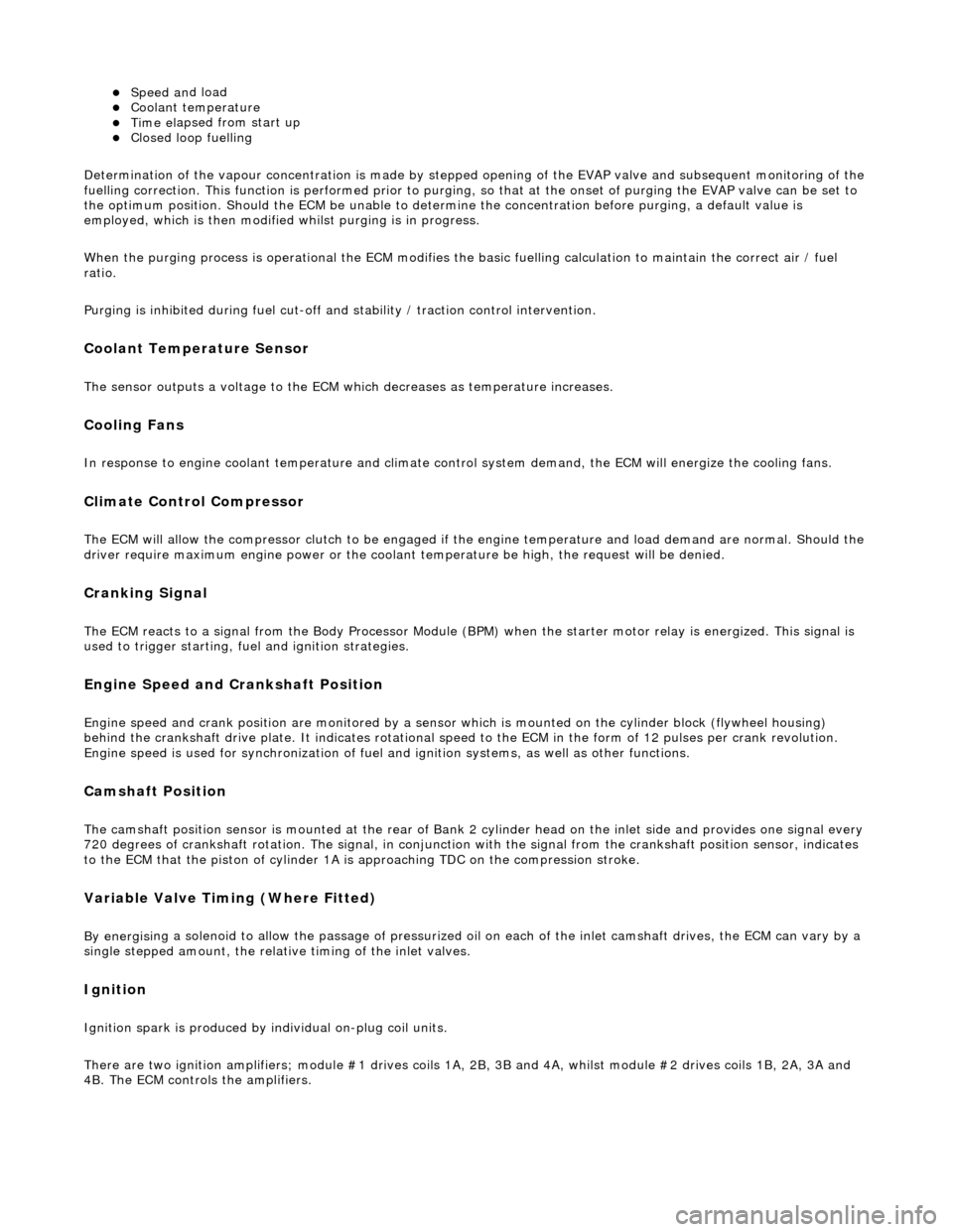
Speed an
d load
Coo
l
ant temperature
Ti
me el
apsed from start up
Cl
osed l
oop fuelling
Determination of the vapour concentration is made by stepped opening of the EVAP valve and subsequent monitoring of the
fuelling correction. This function is performed prior to purging, so that at the onse t of purging the EVAP valve can be set to
the optimum position. Should the ECM be unable to determine the concentration before purging, a default value is
employed, which is then modified whilst purging is in progress.
When the purging process is operational th e ECM modifies the basic fuelling calculation to maintain the correct air / fuel
ratio.
Purging is inhibited during fuel cut-off and stability / traction control intervention.
Coolant Temperature Sen
sor
Th
e
sensor outputs a voltage to the ECM which decreases as temperature increases.
Cooling Fans
In response to engi
ne coolant temperat
u
re and climate control system demand, the ECM will energize the cooling fans.
Climate Control Compressor
The E
C
M will allow the compressor clutch to be engaged if th
e engine temperature and load demand are normal. Should the
driver require maximum engine powe r or the coolant temperature be high, the request will be denied.
Cranking Signal
The ECM reacts to a signal fr
om th
e Body Processor Module (BPM) when the starter motor relay is energi
zed. This signal is
used to trigger starting, fu el and ignition strategies.
Engine Speed and Cranksh
aft Position
Engine
speed and cran
k position are moni
tored by a sensor which is mounted on the cylinder block (flywheel housing)
behind the crankshaft drive plat e. It indicates rotational speed to the ECM in the form of 12 pulses per crank revolution.
Engine speed is used for synchronization of fuel an d ignition systems, as well as other functions.
Camshaft Position
The ca
mshaft position sensor is mounted at
the rear of Bank 2 cylinder head on the inlet side and provides one signal every
720 degrees of crankshaft rotation. The signal, in conjunction with the signal from the crankshaft position sensor, indicates
to the ECM that the piston of cylinder 1A is approaching TDC on the compression stroke.
Variable Valve
Timing (Where Fitted)
By energi
si
ng a solenoid to allow the pass
age of pressurized oil on each of the inle t camshaft drives, the ECM can vary by a
single stepped amount, the relati ve timing of the inlet valves.
Ign
ition
Ignit
i
on spark is produced by
individual on-plug coil units.
There are two ignition amplifiers; module #1 drives coils 1A, 2B, 3B and 4A, whilst module #2 drives coils 1B, 2A, 3A and
4B. The ECM controls the amplifiers.
Page 530 of 2490
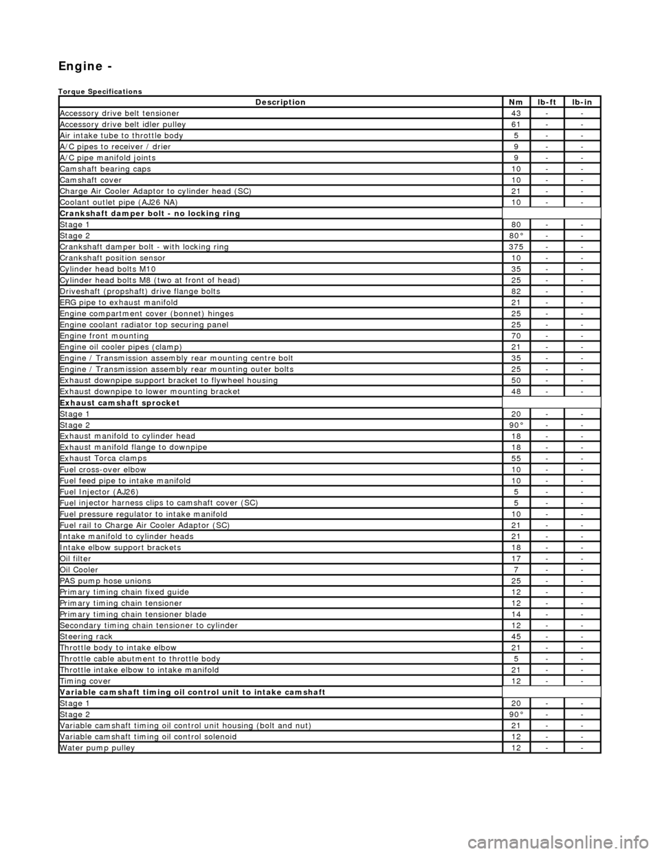
Engi
ne -
Torqu
e Specifications
De
s
cription
Nmlb
-
ft
lb
-
in
A
ccessory
drive belt tensioner
43--
A
ccessory
drive belt idler pulley
61--
Air in
ta
ke tube to throttle body
5--
A/C
pipes t
o receiver / drier
9--
A/C pipe m
anifold joints
9--
Camsh
aft bearin
g caps10--
Ca
msh
aft cove
r10--
Ch
arge Air Co
oler Adaptor to cylinder head (SC)
21--
Co
olan
t outlet pipe (AJ26 NA)
10--
Cran
kshaft damper bolt - no lockin
g ring
St
ag
e 1
80--
Stag
e 2
80°--
C
r
ankshaft damper bolt - with locking ring
37
5--
Cra
nkshaft position sensor
10--
Cy
li
nder head bolts M10
35--
Cy
lin
der head bolts M8 (two at front of head)
25--
Driv
es
haft (propshaft) drive flan
ge bo
l
ts
82--
ERG p
i
pe to exhaust manifold
21--
Engi
ne compartment cover (bonnet) hinges
25--
En
gine
coolant radiator top securing panel
25--
E
ng
ine front mounting
70--
En
gine
oil cooler pipes (clamp)
21--
En
gi
ne / Transmission assembly rear mounting centre bolt
35--
En
gi
ne / Transmission assembly rear mounting outer bolts
25--
Ex
ha
ust downpipe support bracket to flywheel housing
50--
Ex
ha
ust downpipe to lower mounting bracket
48--
E
x
haust camshaft sprocket
St
age 120--
Stage 290 °--
Ex
haust manifold to cylinder head
18--
Ex
ha
ust manifold flange to downpipe
18--
E
x
haust Torca clamps
55--
Fuel cross-over elbo
w
10--
Fu
el f
eed pipe to intake manifold
10--
Fuel
Injector (AJ
26)
5--
Fuel
injector ha
rness clips to camshaft cover (SC)
5--
Fu
el p
ressure re
gu
l
ator to intake manifold
10--
F
u
el rail to Char
ge
A
ir Cooler Adaptor (SC)
21--
In
ta
ke manifold to cylinder heads
21--
Inta
ke elbow support brackets
18--
Oil f
i
lter
17--
Oil C
o
oler
7--
P
AS pu
mp hose unions
25--
P
r
imary timing chain fixed guide
12--
P
r
imary timing chain tensioner
12--
Pr
imary timing chain tensioner blade
14--
S
e
condary timing chain tensioner to cylinder
12--
S
t
eerin
g ra
ck45--
Thro
ttle body to intake elbow
21--
Th
ro
ttle cable abutment to throttle body
5--
Th
ro
ttle intake elbow to intake manifold
21--
Ti
mi
ng cover
12--
Variable camshaft t
i
ming oil control unit to intake camshaft
St
ag
e 1
20--
St
ag
e 2
90
°--
Var
iable camshaft timing oil control unit housing (bolt and nut)
21--
Va
ria
ble camshaft timi
ng oil control solenoid
12--
Wa
ter pump pulley
12--
Page 531 of 2490
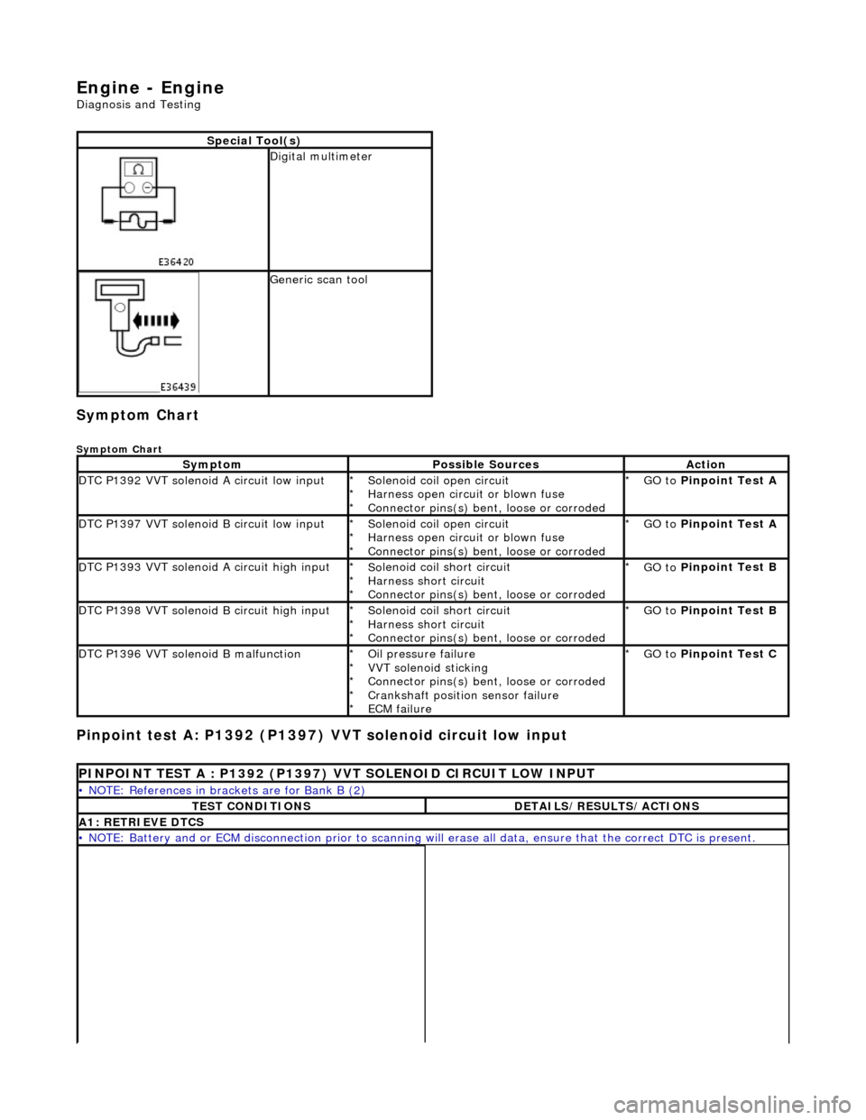
En
gine - Engine
D
iagnosis and Testing
Sym
ptom Chart
Sy
mptom Chart
Pinp
oint test A: P1392 (P1397)
VVT solenoid circuit low input
S
pecial Tool(s)
D
igital multimeter
Generi
c scan tool
Sy
mptom
Possib
le Sources
Acti
on
D
TC P1392 VVT solenoid A circuit low input
So
lenoid coil open circuit
Harness open circuit or blown fuse
Connector pins(s) bent , loose or corroded
*
*
*
GO to
P
inpoint Test A
*
D
TC P1397 VVT solenoid B circuit low input
So
lenoid coil open circuit
Harness open circuit or blown fuse
Connector pins(s) bent , loose or corroded
*
*
*
GO to
P
inpoint Test A
*
D
TC P1393 VVT solenoid A circuit high input
So
lenoid coil short circuit
Harness short circuit
Connector pins(s) bent , loose or corroded
*
*
*
GO to
P
inpoint Test B
*
D
TC P1398 VVT solenoid B circuit high input
So
lenoid coil short circuit
Harness short circuit
Connector pins(s) bent , loose or corroded
*
*
*
GO to
P
inpoint Test B
*
D
TC P1396 VVT solenoid B malfunction
O
il pressure failure
VVT solenoid sticking
Connector pins(s) bent , loose or corroded
Crankshaft position sensor failure
ECM failure
*
*
*
*
*
GO to
P
inpoint Test C
*
P
INPOINT TEST A : P1392 (P1397) VVT SOLENOID CIRCUIT LOW INPUT
•
NOTE: References in brac
kets are for Bank B (2)
T
EST CONDITIONS
D
ETAILS/RESULTS/ACTIONS
A1
: RETRIEVE DTCS
•
NOTE: Battery and or ECM disconnection prior to scanning wi
ll erase all data, ensure that the correct DTC is present.
Page 533 of 2490
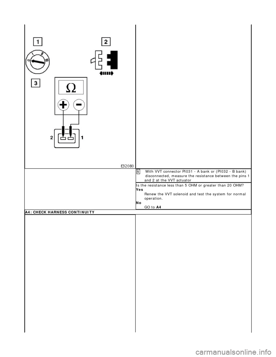
W
ith VVT connector PI031 - A bank or (PI032 - B bank)
disconnected, measure the resistance between the pins 1
and 2 at the VVT actuator
1
I
s the resistance less than 5
OHM or greater than 20 OHM?
Yes Renew the VVT solenoid and te st the system for normal
operation.
No GO to A4
A4: CHECK
HARNESS CONTINUITY
Page 535 of 2490
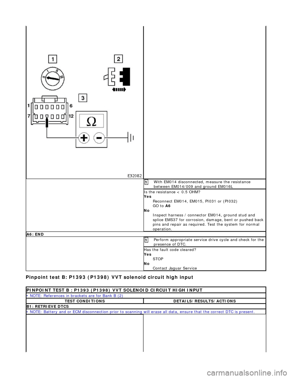
Pin
point test B: P1393 (P1398) VVT solenoid circuit high input
W
ith EM014 disconnected, measure the resistance
between EM014/009 and ground EM016L
1
I
s the resistance < 0.5 OHM?
Yes Reconnect EM014, EM015, PI031 or (PI032)
GO to A6
No Inspect harness / connector EM014, ground stud and
splice EMS37 for corrosion, damage, bent or pushed back
pins and repair as required. Test the system for normal
operation.
A6
: END
Perform
appropriate service drive cycle and check for the
presence of DTC.
1
Has
the fault code cleared?
Yes STOP
No Contact Jaguar Service
P
INPOINT TEST B : P1393 (P1398) VVT SOLENOID CIRCUIT HIGH INPUT
•
NOTE: References in brac
kets are for Bank B (2)
T
EST CONDITIONS
D
ETAILS/RESULTS/ACTIONS
B1
: RETRIEVE DTCS
•
NOTE: Battery and or ECM disconnection prior to scanning wi
ll erase all data, ensure that the correct DTC is present.