SOLENOID JAGUAR X308 1998 2.G Repair Manual
[x] Cancel search | Manufacturer: JAGUAR, Model Year: 1998, Model line: X308, Model: JAGUAR X308 1998 2.GPages: 2490, PDF Size: 69.81 MB
Page 1275 of 2490

Automatic Transmission/Transaxle - 4.0L NA V8 - AJ27/3.2L NA V8 - AJ26
- Diagnostic Strategy
Diagnosis and Testing
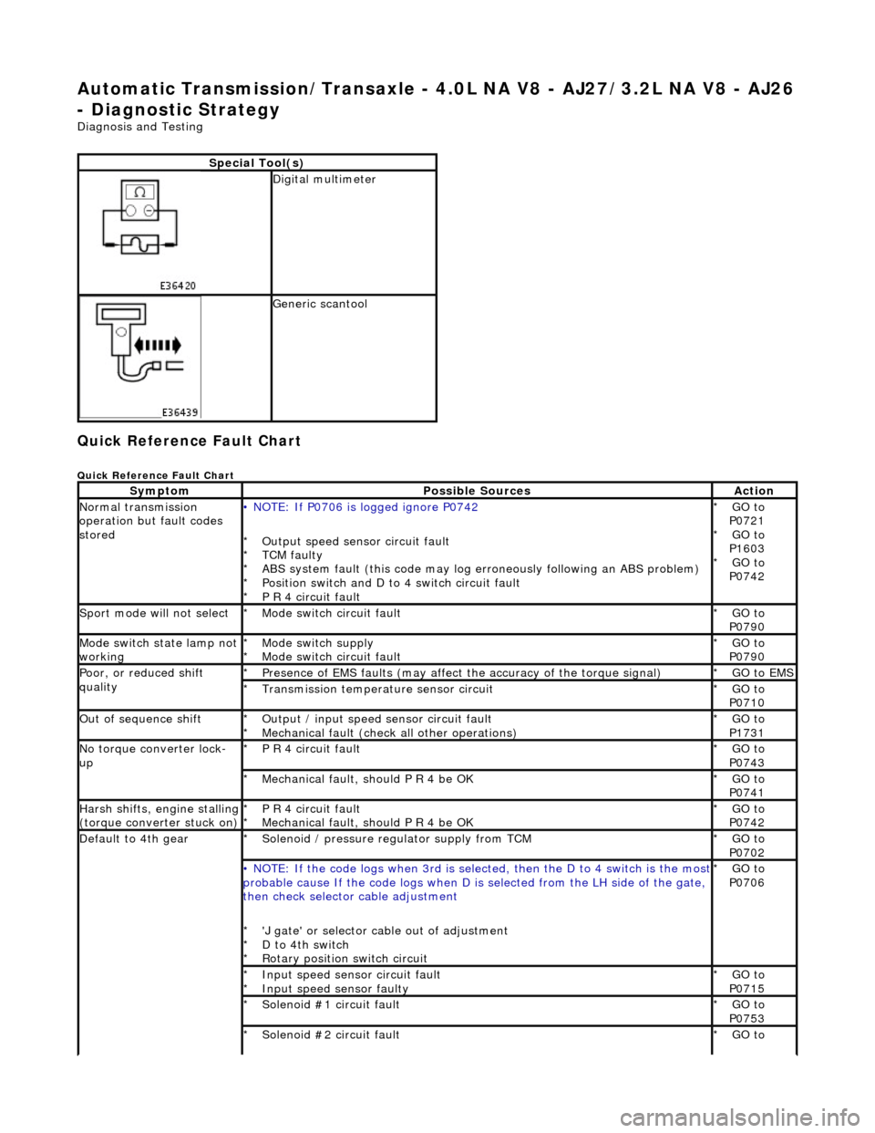
Quick Reference Fault Chart
Quick Reference Fault Chart
Special Tool(s)
Digital multimeter
Generic scantool
SymptomPossible SourcesAction
Normal transmission
operation but fault codes
stored• NOTE: If P0706 is logged ignore P0742
Output speed sensor circuit fault
TCM faulty
ABS system fault (this code may log er roneously following an ABS problem)
Position switch and D to 4 switch circuit fault
P R 4 circuit fault
*
*
*
*
*
GO to
P0721 GO to
P1603 GO to
P0742
*
*
*
Sport mode will not selectMode switch circuit fault
*GO to
P0790
*
Mode switch state lamp not
workingMode switch supply
Mode switch circuit fault
*
*GO to
P0790
*
Poor, or reduced shift
qualityPresence of EMS faults
(may affect the accuracy of the torque signal)
*GO to EMS *
Transmission temperature sensor circuit
*GO to
P0710
*
Out of sequence shiftOutput / input speed sensor circuit fault
Mechanical fault (check all other operations)
*
*GO to
P1731
*
No torque converter lock-
upP R 4 circuit fault
*GO to
P0743
*
Mechanical fault, should P R 4 be OK
*GO to
P0741
*
Harsh shifts, engine stalling (torque converter stuck on)P R 4 circuit fault
Mechanical fault, should P R 4 be OK
*
*GO to
P0742
*
Default to 4th gearSolenoid / pressure regulator supply from TCM
*GO to
P0702
*
• NOTE: If the code logs wh
en 3rd is selected, then the D to 4 switch is the most probable cause If the code logs when D is selected fro m the LH side of the gate,
then check selector cable adjustment
'J gate' or selector ca ble out of adjustment
D to 4th switch
Rotary position switch circuit
*
*
*GO to
P0706
*
Input speed sensor circuit fault
Input speed sensor faulty
*
*GO to
P0715
*
Solenoid #1 circuit fault
*GO to
P0753
*
Solenoid #2 circuit fault
*GO to
*
Page 1276 of 2490

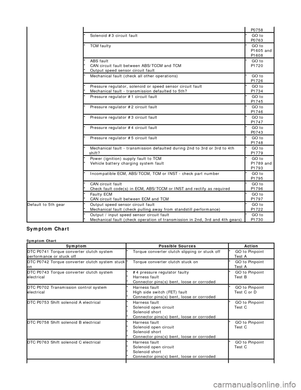
Symptom Chart
Symptom Chart
P0758
Solenoid #3 circuit fault
*GO to
P0763
*
TCM faulty
*GO to
P1605 and
P1608
*
ABS fault
CAN circuit fault between ABS/TCCM and TCM
Output speed sensor circuit fault
*
*
*GO to
P1720
*
Mechanical fault (check all other operations)
*GO to
P1726
*
Pressure regulator, solenoid
or speed sensor circuit fault
Mechanical fault - transmission defaulted to 5th?
*
*GO to
P1734
*
Pressure regulator #1 circuit fault
*GO to
P1745
*
Pressure regulator #2 circuit fault
*GO to
P1746
*
Pressure regulator #3 circuit fault
*GO to
P1747
*
Pressure regulator #4 circuit fault
*GO to
P0743
*
Pressure regulator #5 circuit fault
*GO to
P1748
*
Mechanical fault - transmission defaul
ted during 2nd to 3rd or 3rd to 4th
shift?
*GO to
P1779
*
Power (ignition) supply fault to TCM
Vehicle battery charging system fault
*
*GO to
P1789 and
P1793
*
Incompatible ECM, ABS/TCCM, TCM or INST - check part number
*GO to
P1795
*
CAN circuit fault
Check fault code(s) in ECM, ABS/TCCM or INST and rectify as required
*
*GO to
P1796
*
Faulty ECM
CAN circuit fault between ECM and TCM
*
*GO to
P1797
*
Default to 5th gearOutput speed sensor circuit fault
Mechanical fault (check pulling
away from standstill performance)
*
*GO to
P1722
*
Output / input speed sensor circuit fault
Mechanical fault (check operation of tr
ansmission in 2nd, 3rd and 4th gears)
*
*GO to
P1730
*
SymptomPossible SourcesAction
DTC P0741 Torque converter clutch system
performance or stuck offTorque converter clutch slipping or stuck off
*GO to Pinpoint
Test A
*
DTC P0742 Torque converter clutch system stuck onTorque converter clutch stuck on
*GO to Pinpoint
Test A
*
DTC P0743 Torque converter clutch system
electrical#4 pressure regulator faulty
Harness fault
Connector pins(s) bent
, loose or corroded
*
*
*GO to Pinpoint
Test B
*
DTC P0702 Transmission control system
electricalHarness fault
High side switch (FET) fault
Connector pins(s) bent
, loose or corroded
*
*
*GO to Pinpoint
Test C or D
*
DTC P0753 Shift solenoid A electricalHarness fault
Solenoid open circuit
Solenoid short
Connector pins(s) bent
, loose or corroded
*
*
*
*GO to Pinpoint
Test C
*
DTC P0758 Shift solenoid B electricalHarness fault
Solenoid open circuit
Solenoid short
Connector pins(s) bent
, loose or corroded
*
*
*
*GO to Pinpoint
Test C
*
DTC P0763 Shift solenoid C electricalHarness fault
Solenoid open circuit
Solenoid short
Connector pins(s) bent
, loose or corroded
*
*
*
*GO to Pinpoint
Test C
*
Page 1289 of 2490

With EM007 and EM046 disconnected, measure the
resistance between EM007/052 and EM007/054 1
Repeat for EM007/053 and EM007/054 2
> 10 MOHM?
Yes GO to C7
No Inspect harness / connectors EM007 for damage, corrosion,
bent / pushed back pins. Repa ir as necessary and test the
system for normal operation.
C7: CHECK HARNESS CONTINUITY - SOLENOID
Page 1290 of 2490

With EM007 and EM046 disconnected, measure the
resistance in turn; 1
EM007/030 and EM046/008 2
EM007/033 and EM046/009 3
EM007/032 and EM046/004 4
Is the resistance < 0.5 OHM?
Yes GO to C8
No Inspect harness / connectors EM007 and EM046 for damage,
corrosion, bent / pushed back pins. Repair as necessary and
test the system for normal operation.
C8: CHECK FOR SOLENOID SHORT TO B+
Page 1292 of 2490

With EM007 and EM046 disconnected, measure the
resistance between EM007/030 and EM008R
Repeat for
1
EM007/033 and EM008R 2
EM007/032 and EM008R 3
Is the resistance > 10 MOHM?
Yes GO to C10
No
Inspect harness / connectors EM007 for damage, corrosion,
bent / pushed back pins. Repa ir as necessary and test the
system for normal operation.
C10: CHECK FOR SOLENOID SHORT TO IGNITION
Page 1293 of 2490

With EM007 and EM046 disconnected, measure the
resistance between EM007/030 and EM007/054
Repeat for
1
EM007/033 and EM007/054 2
EM007/032 and EM007/054 3
Is the resistance > 10 MOHM?
Yes Reconnect EM046
GO to C11
No Inspect harness / connectors EM007 for damage, corrosion,
bent / pushed back pins. Repa ir as necessary and test the
system for normal operation.
C11: CHECK INTERNAL HA RNESS AND COMPONENT CONTINUITY - SOLENOIDS
Page 1294 of 2490

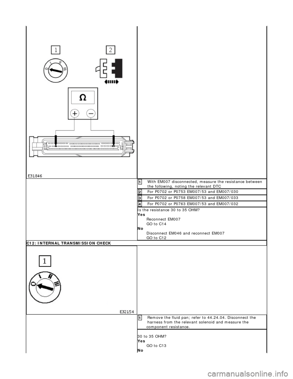
With EM007 disconnected, measure the resistance between
the following, noting the relevant DTC 1
For P0702 or P0753 EM007/53 and EM007/030 2
For P0702 or P0758 EM007/53 and EM007/033 3
For P0702 or P0763 EM007/53 and EM007/032 4
Is the resistance 30 to 35 OHM?
Yes Reconnect EM007
GO to C14
No Disconnect EM046 and reconnect EM007
GO to C12
C12: INTERNAL TRANSMISSION CHECK
Remove the fluid pan; refer to 44.24.04. Disconnect the
harness from the relevant solenoid and measure the
component resistance. 1
30 to 35 OHM?
Yes GO to C13
No
Page 1295 of 2490

Pinpoint test D: P0702, P1745, P1746, P1747, P0743, P1748
Renew the solenoid; refer to 44.15.50.
C13: INTERNAL TRANSMISSION HARNESS CHECK
Measure the resistance from transmission internal harness
multiplug to the relevant solenoid connector 1
Is the resistance < 0.5 OHM?
Yes GO to C14
No Renew the internal harnes s; refer to 44.15.35.
C14: END
Cycle the ignition ON - (OFF for 2 minutes) - ON, start the
engine and run >1600 rpm 1
Has the fault code cleared?
Yes
STOP
No P0702 present?
Yes GO to D1
No P0753, P0758, P0763 present?
Yes Contact Jaguar Service
PINPOINT TEST D : P0702, P1745, P1746, P1747, P0743, P1748
TEST CONDITIONSDETAILS/RESULTS/ACTIONS
D1: RETRIEVE DTCS
• NOTE: Battery and or ECM disconnection prior to scanning wi ll erase all data, ensure that the correct DTC is present
Connect the scan tool 1
Have the DTC(s) and freeze frame data been recorded?
Yes GO to D2
D2: CHECK HARNESS +VE CONTINUITY
Page 1339 of 2490

Automatic Transmission/Transaxle - 4.0L NA V8 - AJ27/3.2L NA V8 - AJ26
- Electronic Pressure Control (EPC) Solenoid
In-vehicle Repair
Removal
1. Disconnect battery ground cable.
Remove the battery cover.
2. Raise the vehicle on a suitable lift.
2. WARNING: TRANSMISSION FLUID MAY CAUSE
SEVERE BURNS, ENSURE THAT ALL SAFETY PROCEDURES
ARE OBSERVED.
Carefully remove the drain plug and drain the
transmission fluid.
3. Remove the twenty-two fixings which secure the fluid pan .
Remove the fluid pan and all traces of gasket material.
4. Disconnect regulator / solenoid connectors.
5. Remove RH rear valve body securing screws.
Page 1340 of 2490

Installation
6. Remove the nine screws from th e pressure regulator / solenoid
retaining plate.
7. Remove the relevant pressure regulator.
1. Installation is the reverse of the removal procedure, noting
that a new pressure regulator 'O' ring MUST be used.
Fit the nine screws securing the pressure regulator /
solenoid retaining plate and ti ghten to the specified torque
figure.
2. Refit the RH rear valve body secu ring screws and tighten to the
specified torque figure.