WIRING JAGUAR X308 1998 2.G Owner's Manual
[x] Cancel search | Manufacturer: JAGUAR, Model Year: 1998, Model line: X308, Model: JAGUAR X308 1998 2.GPages: 2490, PDF Size: 69.81 MB
Page 1162 of 2490
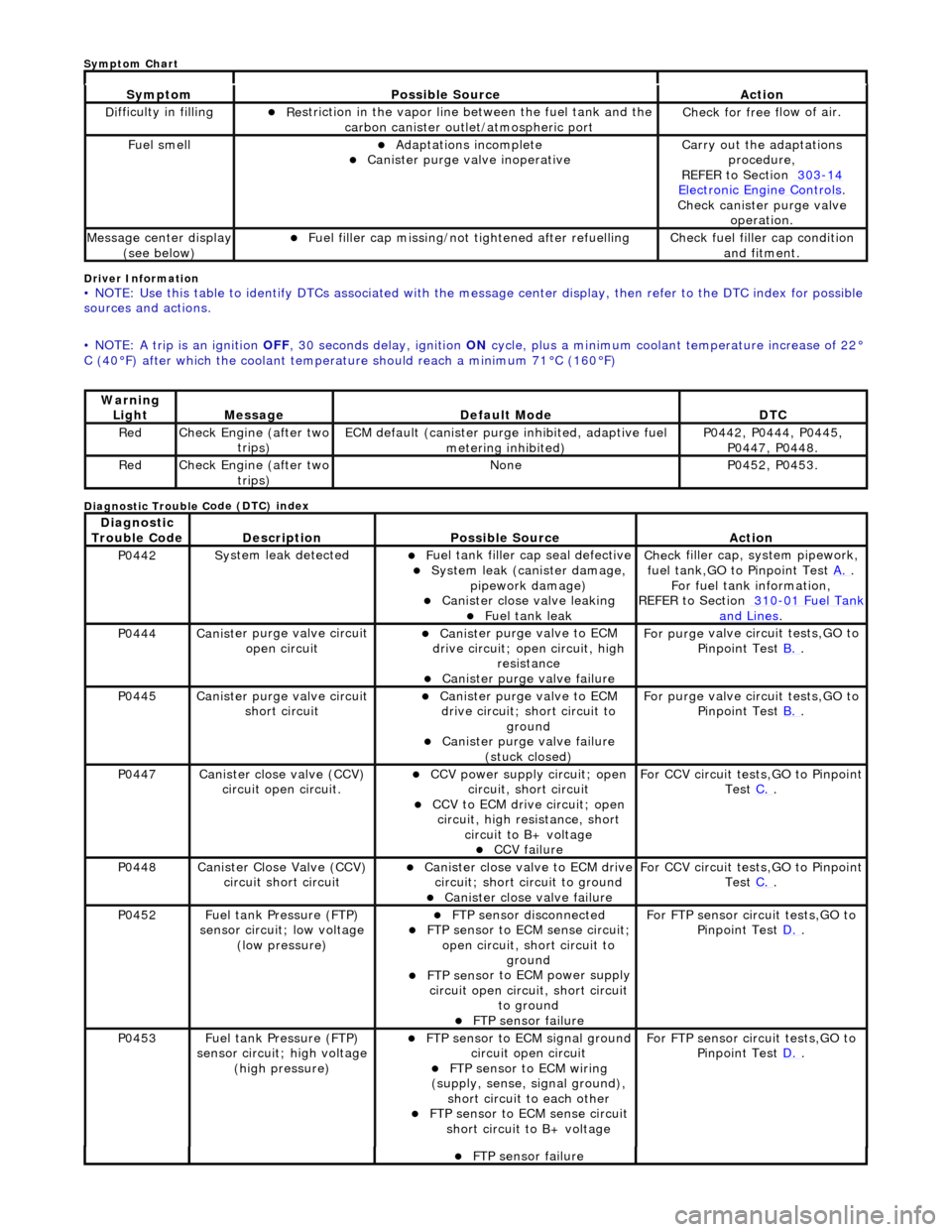
Driver Info
rmation
•
NOTE: Use this table to identify DTCs associated with the me
ssage center display, then refer to the DTC index for possible
sources and actions.
• NOTE: A trip is an ignition OFF, 30 seconds delay, ignition ON cycle, plus a minimum coolant temperature increase of 22°
C (40В°F) after which the coolant temperat ure should reach a minimum 71В°C (160В°F)
Diagnostic Trouble C
ode (DTC) index
Sy
m
ptom
Possib
l
e Source
Acti
o
n
D
i
fficulty in filling
пЃ¬R
e
striction in the vapor line between the fuel tank and the
carbon canister outlet/atmospheric port
Check f or free f
low of air.
F
u
el smell
пЃ¬Adaptat
i
ons incomplete
пЃ¬Cani
st
er purge valve inoperative
Carry
o
ut the adaptations
procedure,
REFER to Section 303
-14 Ele c
tronic Engine Controls
.
Chec k cani
ster purge valve
operation.
M e
ssage center display
(see below)
пЃ¬Fue l
filler cap missing/not
tightened after refuelling
Check fu
el filler cap condition
and fitment.
Warning Li
ght
Mess
age Defaul
t Mode
DT
C
RedCheck Engine (after two
trip
s)
ECM de
fa
ult (canister purge inhibited, adaptive fuel
metering inhibited)
P0442,
P0444, P0445,
P0447, P0448.
Re dCheck Engine (after two
trip
s)
No
neP04 52,
P0453.
Di
agno
stic
Trouble Code
De scr
iption
Possib
l
e Source
Acti
o
n
P0442Sy
st
em leak detected
пЃ¬F
u
el tank filler cap seal defective
пЃ¬Sy
ste
m leak (c
anister damage,
pipework damage)
пЃ¬Cani st
er close valve leaking
пЃ¬F
u
el tank leak
Chec
k fi
ller cap,
system pipework,
fuel tank,GO to Pinpoint Test A.
.
F o
r fuel tank information,
REFER to Section 310
-01 Fu
el Tank
and Lines.
P0444Canist
er purge valve circuit
open circuit
пЃ¬Cani st
er purge valve to ECM
drive circuit; open circuit, high
resistance
пЃ¬Cani st
er purge valve failure
F
or purge
valve circuit tests,GO to
Pinpoint Test B.
.
P0445Canist
er purge valve circuit
short circuit
пЃ¬Cani st
er purge valve to ECM
drive circuit; short circuit to ground
пЃ¬Canist
er purge valve failure
(stuck closed)
F or purge
valve circuit tests,GO to
Pinpoint Test B.
.
P0447Canist
er close valve (CCV)
circuit open circuit.
пЃ¬CCV power su pply ci
rcuit; open
circuit, short circuit
пЃ¬CCV to ECM drive circuit;
open
circuit, high resistance, short circuit to B+ voltage
пЃ¬CCV failure
Fo
r CCV circuit tests,GO to Pinpoint
Test C.
.
P0448Canist
er Close Valve (CCV)
circuit short circuit
пЃ¬Cani st
er close valve to ECM drive
circuit; short circuit to ground
пЃ¬Cani st
er close valve failure
F
o
r CCV circuit tests,GO to Pinpoint
Test C.
.
P0452 Fu
el tank Pressure (FTP)
sensor circuit; low voltage (low pressure)
пЃ¬FTP sen
sor disconnected
пЃ¬FTP sen
sor to ECM sense circuit;
open circuit, short circuit to ground
пЃ¬FTP sens
or to ECM power supply
circuit open circuit, short circuit to ground
пЃ¬FT
P sensor failure
For FT
P se
nsor circuit tests,GO to
Pinpoint Test D.
.
P0453Fu
el tank Pressure (FTP)
sensor circuit; high voltage
(high pressure)
пЃ¬FTP sen
sor to ECM signal ground
circuit open circuit
пЃ¬F T
P sensor to ECM wiring
(supply, sense, signal ground),
short circuit to each other
пЃ¬FTP sen
sor to ECM sense circuit
short circuit to B+ voltage
For FT P se
nsor circuit tests,GO to
Pinpoint Test D.
.
пЃ¬FT
P sensor failure
Sym
ptom Chart
Page 1163 of 2490
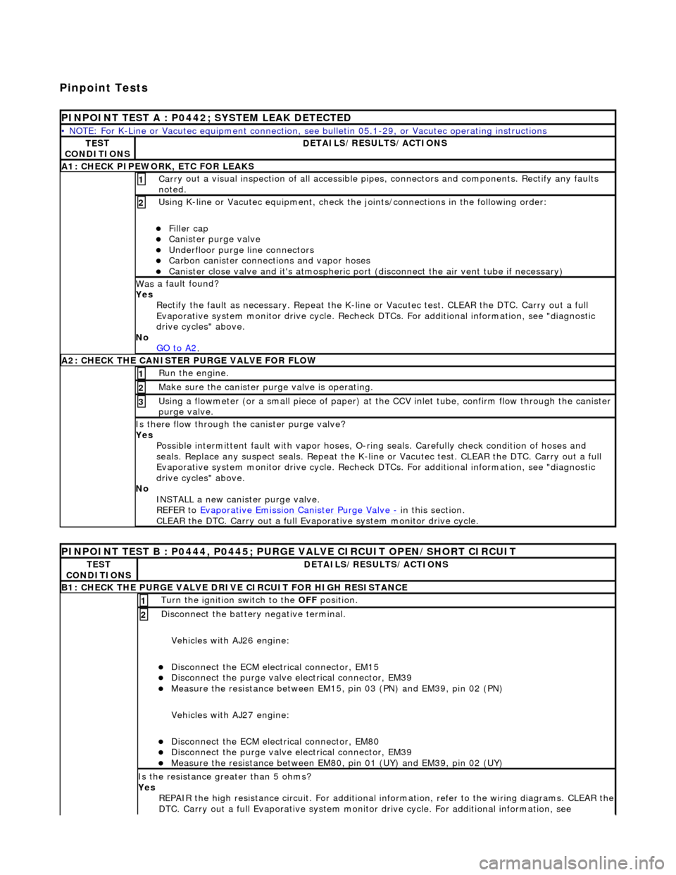
Pinpoint Tests
P
INPOINT TEST A : P0442; SYSTEM LEAK DETECTED
•
NOTE: For K-Line or Vacutec equipment connection, see bulletin 05.1-29, or Vacutec operating instructions
TE
ST
CONDITIONS
D
ETAILS/RESULTS/ACTIONS
A
1: CHECK PIPEWORK, ETC FOR LEAKS
Carr
y out a visual inspection of all accessible pipes, connectors and components. Rectify any faults
noted.
1
U
sing K-line or Vacutec equipment, check the
joints/connections in the following order:
пЃ¬Fi
ller cap
пЃ¬Cani
ster purge valve
пЃ¬Underfl
oor purge line connectors
пЃ¬Carbon
canister connections and vapor hoses
пЃ¬Cani
ster close valve and it's atmospheric port (disconnect the air vent tube if necessary)
2
Was
a fault found?
Yes Rectify the fault as necessary. Re peat the K-line or Vacutec test. CLEAR the DTC. Carry out a full
Evaporative system monitor drive cycle. Recheck DT Cs. For additional information, see "diagnostic
drive cycles" above.
No GO to A2
.
A2: CHECK
THE CA
NISTER PURGE VALVE FOR FLOW
Ru
n the engine.
1
Make sure the canister purge
valve is operating.
2
Using a flowmeter
(or a small piece
of paper) at the CCV inlet tube, confirm flow through the canister
purge valve.
3
Is th
ere flow through the canister purge valve?
Yes Possible intermittent faul t with vapor hoses, O-ring seals. Carefully check condition of hoses and
seals. Replace any suspect seals. Repeat the K-line or Vacutec test. CLEAR the DTC. Carry out a full
Evaporative system monitor drive cycle. Recheck DT Cs. For additional information, see "diagnostic
drive cycles" above.
No INSTALL a new canister purge valve.
REFER to Evaporative Emission Canister Purge Valve
- in t
his section.
CLEAR the DTC. Carry out a full Evap orative system monitor drive cycle.
P
INPOINT TEST B : P0444, P0445; PURGE VALVE CIRCUIT OPEN/SHORT CIRCUIT
TE
ST
CONDITIONS
D
ETAILS/RESULTS/ACTIONS
B1: CHECK
THE PURGE VALVE DRIV
E CIRCUIT FOR HIGH RESISTANCE
Turn the ignition swi
tch to the OFF
position.
1
Di
sconnect the battery negative terminal.
Vehicles with AJ26 engine:
пЃ¬Disc
onnect the ECM electrical connector, EM15
пЃ¬Di
sconnect the purge valve electrical connector, EM39
пЃ¬Meas
ure the resistance between EM15,
pin 03 (PN) and EM39, pin 02 (PN)
Vehicles with AJ27 engine:
пЃ¬Disc
onnect the ECM electrical connector, EM80
пЃ¬Di
sconnect the purge valve electrical connector, EM39
пЃ¬Meas
ure the resistance between EM80, pin 01 (UY) and EM39, pin 02 (UY)
2
Is th
e resistance greater than 5 ohms?
Yes REPAIR the high resistance circuit. For additional information, refer to the wiring diagrams. CLEAR the
DTC. Carry out a full Evaporative system monitor drive cycle. For additional information, see
Page 1164 of 2490
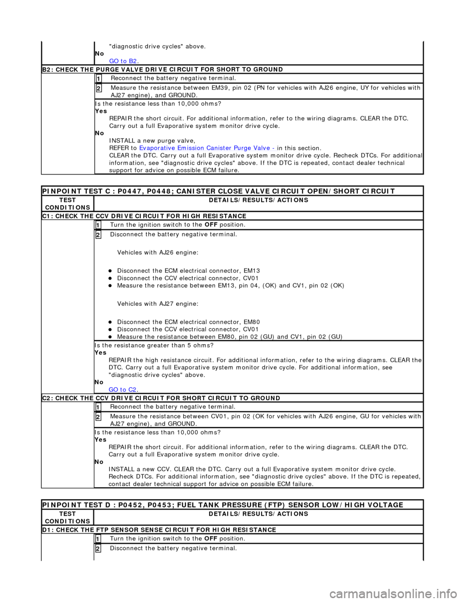
"d
iagnostic drive cycles" above.
No GO to B2
.
B2: CHECK THE PURGE VALVE DR
IV
E CIRCUIT FOR SHORT TO GROUND
Re
connect the battery negative terminal.
1
Meas
ure t
he resistance between EM39, pin 02 (PN for vehicles with AJ26
engine, UY for vehicles with
AJ27 engine), and GROUND.
2
Is t
he resistance less than 10,000 ohms?
Yes REPAIR the short circuit. For addi tional information, refer to the wiring diagrams. CLEAR the DTC.
Carry out a full Evaporative system monitor drive cycle.
No INSTALL a new purge valve,
REFER to Evaporative Emission Canister Purge Valve
- in thi
s section.
CLEAR the DTC. Carry out a full Evaporative system monitor drive cycle. Recheck DTCs. For additional
information, see "diagnostic drive cycles" above. If the DTC is repeated, contact dealer technical
support for advice on possible ECM failure.
PI
NPOINT TEST C : P0447, P0448; CANISTER CLOSE VALVE CIRCUIT OPEN/SHORT CIRCUIT
TE
S
T
CONDITIONS
D E
TAILS/RESULTS/ACTIONS
C1
: CH
ECK THE CCV DRIVE CIRCUIT FOR HIGH RESISTANCE
Turn the ignition swi
t
ch to the
OFF position.
1
Disc
onnect the battery negative terminal.
Vehicles with AJ26 engine:
пЃ¬Disc onne
ct the ECM electrical connector, EM13
пЃ¬Di
sc
onnect the CCV electrical connector, CV01
пЃ¬Meas
ure t
he resistance between EM13, pi
n 04, (OK) and CV1, pin 02 (OK)
Vehicles with AJ27 engine:
пЃ¬Disc onne
ct the ECM electrical connector, EM80
пЃ¬Di
sc
onnect the CCV electrical connector, CV01
пЃ¬Meas
ure t
he resistance between EM80,
pin 02 (GU) and CV1, pin 02 (GU)
2
Is the res
istance greater than 5 ohms?
Yes REPAIR the high resistance circuit. For additional information, refer to the wiring diagrams. CLEAR the
DTC. Carry out a full Evaporative system monitor drive cycle. For additional information, see
"diagnostic drive cycles" above.
No GO to C2
.
C2: CH
ECK THE CCV DRIVE CIRCUI
T FOR SHORT CIRCUIT TO GROUND
Re
connect the battery negative terminal.
1
Meas
ure t
he resistance between CV01,
pin 02 (OK for vehicles with AJ26 engine, GU for vehicles with
AJ27 engine), and GROUND.
2
Is t
he resistance less than 10,000 ohms?
Yes REPAIR the short circuit. For addi tional information, refer to the wiring diagrams. CLEAR the DTC.
Carry out a full Evaporative system monitor drive cycle.
No INSTALL a new CCV. CLEAR the DTC. Carry out a fu ll Evaporative system monitor drive cycle.
Recheck DTCs. For additional inform ation, see "diagnostic drive cycles" above. If the DTC is repeated,
contact dealer technical support for advice on possible ECM failure.
P INPOINT TES
T D : P0452, P0453; FUEL TANK
PRESSURE (FTP) SENSOR LOW/HIGH VOLTAGE
TES
T
CONDITIONS
DE
TAILS/RESULTS/ACTIONS
D
1:
CHECK THE FTP SENSOR SENSE CIRCUIT FOR HIGH RESISTANCE
Turn the ignition swi
t
ch to the OFF
position.
1
Disc
onnect the battery negative terminal.
2
Page 1165 of 2490

Vehicles with AJ26 en
gine:
пЃ¬D
isconnect the ECM electrical connector, EM11
пЃ¬Di
sconnect the FTP sensor electrical connector, FP01
пЃ¬Meas
ure the resistance between EM11,
pin 07 (RG) and FP01, pin 02 (RG)
Vehicles with AJ27 engine:
пЃ¬D
isconnect the ECM electrical connector, EM81
пЃ¬Di
sconnect the FTP sensor electrical connector, FP01
пЃ¬Meas
ure the resistance between EM81,
pin 16 (RG) and FP01, pin 02 (RG)
Is th
e resistance greater than 5 ohms?
Yes REPAIR the high resistance circuit. For additional information, refer to the wiring diagrams. CLEAR the
DTC. Carry out a full Evaporative system monitor drive cycle. For additional information, see
"diagnostic drive cycles" above.
No GO to D2
.
D2: CHECK
THE FTP SENSOR SENSE CI
RCUIT FOR SHORT CIRCUIT TO GROUND
R
econnect the battery negative terminal.
1
Meas
ure the resistance between
FP01, pin 07 (RG) and GROUND.
2
Is
the resistance less than 10,000 ohms?
Yes REPAIR the short circuit. For addi tional information, refer to the wiring diagrams. CLEAR the DTC.
Carry out a full Evaporative system monitor drive cycle.
No GO to D4
.
D3: CHECK
THE FTP SENSOR SENSE CIRCUI
T FOR SHORT CIRCUIT TO HIGH VOLTAGE
Turn the ignition swi
tch to the ON
position.
1
Measure the
voltage between FP
01, pin 02 (RG) and GROUND.
2
Is th
e voltage greater than 3 volts?
Yes REPAIR the short circuit. For addi tional information, refer to the wiring diagrams. CLEAR the DTC.
Carry out a full Evaporative system monitor drive cycle.
No GO to D4
.
D
4: CHECK THE FTP SENSOR SIGNAL GROUND CIRCUIT FOR HIGH RESISTANCE
Di
sconnect the battery negative terminal.
Vehicles with AJ26 engine:
пЃ¬D
isconnect the ECM electrical connector, EM10
пЃ¬Meas
ure the resistance between EM11, pin 12 (BG) and FP01, pin 01 (BG)
пЃ¬Meas
ure the resistance between EM10, pin 20 (BG) and FP01, pin 01 (BG)
Vehicles with AJ27 engine:
пЃ¬Re
connect the ECM electrical connector, EM81
пЃ¬D
isconnect the ECM electrical connector, EM82
пЃ¬D
isconnect the ECM electrical connector, EM83
пЃ¬Meas
ure the resistance between EM82, pin 07 (BG) and FP01, pin 01 (BG)
пЃ¬Meas
ure the resistance between EM83, pin 13 (BG) and FP01, pin 01 (BG)
1
Is either resi
stance
greater than 5 ohms?
Yes REPAIR the high resistance circui t. This circuit includes harness splice, EMS02. For additional
information, refer to the wiring diagrams. CLEAR the DTC. Carry out a full Evaporative system
monitor drive cycle. For additional informat ion, see "diagnostic drive cycles" above.
No GO to D5
.
D5:
CHECK THE FTP SENSOR SIGNAL GROUND
CIRCUIT FOR SHORT CIRCUIT TO GROUND
R
econnect the battery negative terminal.
1
Meas
ure the resistance between
FP01, pin 01 (BG) and GROUND.
2
Is
the resistance less than 10,000 ohms?
Page 1166 of 2490

Yes
R
EPAIR the short circuit. For addi
tional information, refer to the wiring diagrams. CLEAR the DTC.
Carry out a full Evaporative system monitor drive cycle.
No GO to D6
.
D6: CHECK
THE FTP SENSOR POWER SU
PPLY CIRCUIT FOR HIGH RESISTANCE
Disc
onnect the battery negative terminal.
Vehicles with AJ26 engine:
пЃ¬Measure t
he resistance between EM11,
pin 08 (UW) and FP01, pin 03 (UW)
пЃ¬Measure t
he resistance between EM10,
pin 21 (UW) and FP01, pin 03 (UW)
Vehicles with AJ27 engine:
пЃ¬Meas ure t
he resistance between EM82,
pin 01 (OY) and FP01, pin 03 (OY)
пЃ¬Measure t
he resistance between EM83,
pin 05 (OY) and FP01, pin 03 (OY)
1
Is either resistance greater
than 5 ohms?
Yes
REPAIR the high resistance circui t. This circuit includes harness splice, EMS01. For additional
information, refer to the wiring diagrams. CLEAR the DTC. Carry out a full Evaporative system
monitor drive cycle. For additional informat ion, see "diagnostic drive cycles" above.
No GO to D7
.
D7: CHECK
THE FTP SENSOR WIRING
FOR SHORT CIRCUIT TO EACH OTHER
Measure
the resistance between FP01, pins 01 (BG) and 02 (RG).
1
M
e
asure the resistance between FP01, pins 02 (RG) and 03 (UW).
2
Is either resi
stance le
ss than 10,000 ohms?
Yes REPAIR the short circuit. For addi tional information, refer to the wiring diagrams. CLEAR the DTC.
Carry out a full Evaporative system monitor drive cycle.
No INSTALL a new FTP sensor. CLEAR the DTC. Carry out a full Evaporative system monitor drive cycle.
For additional information, see "diagnostic drive cycles" above.
Page 1192 of 2490
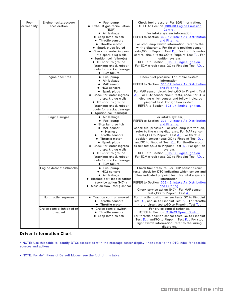
Driver Information
Chart
•
NOTE: Use this table to identify DTCs associated with the me
ssage center display, then refer to the DTC index for possible
sources and actions.
• NOTE: For definitions of Default Modes, see the foot of this table.
Poor
dr iveabilityEngine h e
sitates/poor
acceleration
пЃ¬Fue l
pump
пЃ¬Exhaus
t gas
recirculation
(EGR)
пЃ¬Air leakage пЃ¬Stop lamp swi t
ch
пЃ¬Throttl
e
sensors
пЃ¬Throttl
e
motor
пЃ¬Spark
plugs
fouled
пЃ¬Check f
o
r water ingress
into spark plug wells
пЃ¬Ignition coil fail
ure(s)
пЃ¬HT sh
o
rt to ground
(tracking) check rubber
boots for cracks/damage
пЃ¬ECM failu r
e
Check f
u
el pressure. For EGR information,
REFER to Section 303
-08 En gin
e Emission
Control.
F or i
ntake system information,
REFER to Section 303
-1 2
Intake Air Distribution
and F
ilt
ering
.
F or stop l
amp switch in
formation, refer to the
wiring diagrams. For throttle position sensor
tests,GO to Pinpoint Test D.
. Fo
r throttle motor
control circuit tests,GO to Pinpoint Test T.
. For
igni t
ion system,
REFER to Section 303
-07 En
gine Ignition
.
F or ECM
circuit tests,GO to Pinpoint Test
AD.
.
Engine backfiresпЃ¬Fuel
pump
пЃ¬Air leakage пЃ¬MAF se
nsor
пЃ¬HO2 sensors
пЃ¬Spark plugs пЃ¬Check fo
r water ingress
into spark plug wells
пЃ¬HT sh o
rt to ground
(tracking) check rubber
boots for cracks/damage
пЃ¬Ignition coil fail
ure(s)
Chec
k fu
el pressure. For intake system
information,
REFER to Section 303
-12
Intake Air Distribution
and Filt
ering
.
F or MAF sensor ci
rcuit test
s,GO to Pinpoint Test
A.
. F or HO2 sensor
circui
t tests, check for DTC
indicating which sensor and follow indicated pinpoint test. For ignition system,
REFER to Section 303
-07 En
gine Ignition
.
Engine
s
urges
пЃ¬Air leakage
пЃ¬Fuel
pump
пЃ¬Stop lamp swit
ch
пЃ¬MAF s
e
nsor
пЃ¬Harness пЃ¬Throttl
e
sensors
пЃ¬Throttl
e
motor
пЃ¬Spark plugs
пЃ¬Check fo
r water ingress
into spark plug wells
пЃ¬HT sh o
rt to ground
(tracking) check rubber
boots for cracks/damage
пЃ¬ECM failu r
e
Fo
r
intake system,
REFER to Section 303
-1 2
Intake Air Distribution
and Filt
ering
.
Check fu
el pressure. For
stop lamp information,
refer to the wiring diagrams. For MAF sensor tests,GO to Pinpoint Test A.
. Fo
r throttle
position sensor tests,GO to Pinpoint Test D.
,
a n
dGO to Pinpoint Test
K.
. Fo
r throttle motor
circuit tests,GO to Pinpoint Test T.
. For ig
nition
system,
REFER to Section 303
-07 En
gine Ignition
.
F or ECM
circuit tests,GO to Pinpoint Test
AD.
.
Engine detonates/k
nocks
пЃ¬Fue
l
pump
пЃ¬HO2 sensors
пЃ¬Air leakage пЃ¬Blocked part-load breather
(s
ervice action S474)
пЃ¬Mass ai
r fl
ow (MAF) sensor
Chec
k fu
el pressure. Fo
r HO2 sensor circuit
tests, check for DTC indicating which sensor and
follow indicated pinpoint test. For intake system
information,
REFER to Section 303
-1 2
Intake Air Distribution
and Filt
ering
.
Check service action S474
. For MAF sensor
tests,GO to Pinpoint Test A.
.
No t
hrottle response
пЃ¬Traction contr
o
l invoked
пЃ¬Throttl
e
sensors
пЃ¬Throttl
e
motor
Fo
r th
rottle position sensor tests,GO to Pinpoint
Test D.
, andG O to Pinpoint
Test
K.
. Fo
r throttle
motor circuit tests,GO to Pinpoint Test T.
.
Cru i
se control inhibited or
disabled
пЃ¬Cru i
se control switch
пЃ¬Throttle
sensors
пЃ¬Stop lamp swit
ch
For cru
i
se control switches,
REFER to Section 310
-03
Speed Control
.
For th
rottle position sensor tests,GO to Pinpoint
Test D.
, andG O to Pinpoint
Test
K.
. For s t
op
light switch information, refer to the wiring diagrams.
Page 1195 of 2490
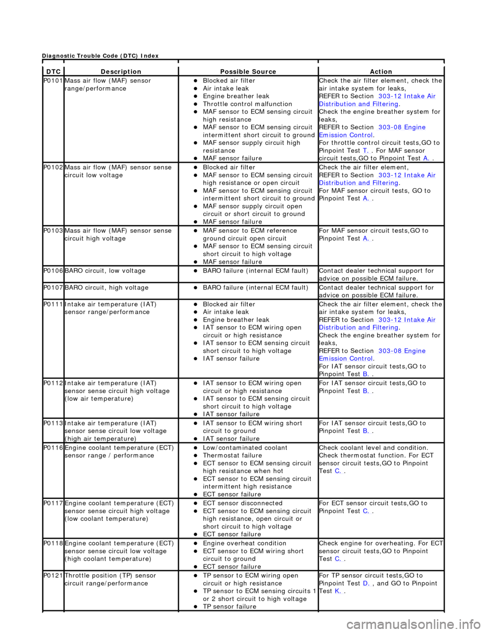
DT
C
De
scription
Possib
le Source
Acti
on
P0101Mass ai
r flow (MAF) sensor
range/performance
пЃ¬Bl
ocked air filter
пЃ¬Air
intake leak
пЃ¬Engine
breather leak
пЃ¬Throttl
e control malfunction
пЃ¬MAF
sensor to ECM sensing circuit
high resistance
пЃ¬MAF
sensor to ECM sensing circuit
intermittent short circuit to ground
пЃ¬MAF
sensor supply circuit high
resistance
пЃ¬MAF
sensor failure
Chec
k the air filter element, check the
air intake system for leaks,
REFER to Section 303
-1
2 Intake Air
Distribu
tion and Filtering
.
Chec
k the engine breather system for
leaks,
REFER to Section 303
-08
Engine
Emissi
on Control
.
F
or throttle control circuit tests,GO to
Pinpoint Test T.
. Fo
r MAF sensor
circuit tests,GO to Pinpoint Test A.
.
P0102Mass ai
r flow (MAF) sensor sense
circuit low voltage
пЃ¬Bl
ocked air filter
пЃ¬MAF
sensor to ECM sensing circuit
high resistance or open circuit
пЃ¬MAF
sensor to ECM sensing circuit
intermittent short circuit to ground
пЃ¬MAF
sensor supply circuit open
circuit or short circuit to ground
пЃ¬MAF
sensor failure
Chec
k the air filter element,
REFER to Section 303
-1
2 Intake Air
Distribu
tion and Filtering
.
For MAF
sensor circuit tests, GO to
Pinpoint Test A.
.
P0103Mass ai
r flow (MAF) sensor sense
circuit high voltage
пЃ¬MAF
sensor to ECM reference
ground circuit open circuit
пЃ¬MAF
sensor to ECM sensing circuit
short circuit to high voltage
пЃ¬MAF sensor
failure
For MAF
sensor circuit tests,GO to
Pinpoint Test A.
.
P0106BARO ci
rcuit, low voltage
пЃ¬BARO f
ailure (internal ECM fault)
Contact deal
er technical support for
advice on possible ECM failure.
P0107BARO ci
rcuit, high voltage
пЃ¬BARO f
ailure (internal ECM fault)
Contact deal
er technical support for
advice on possible ECM failure.
P0111In
take air temperature (IAT)
sensor range/performance
пЃ¬Bl
ocked air filter
пЃ¬Air
intake leak
пЃ¬Engine
breather leak
пЃ¬IAT sensor to
ECM wiring open
circuit or high resistance
пЃ¬IAT se
nsor to ECM sensing circuit
short circuit to high voltage
пЃ¬IAT sensor fail
ure
Chec
k the air filter element, check the
air intake system for leaks,
REFER to Section 303
-1
2 Intake Air
Distribu
tion and Filtering
.
Chec
k the engine breather system for
leaks,
REFER to Section 303
-08
Engine
Emissi
on Control
.
F
or IAT sensor circuit tests,GO to
Pinpoint Test B.
.
P0112In
take air temperature (IAT)
sensor sense circuit high voltage
(low air temperature)
пЃ¬IAT sensor to
ECM wiring open
circuit or high resistance
пЃ¬IAT se
nsor to ECM sensing circuit
short circuit to high voltage
пЃ¬IAT sensor fail
ure
F
or IAT sensor circuit tests,GO to
Pinpoint Test B.
.
P0113In
take air temperature (IAT)
sensor sense circuit low voltage
(high air temperature)
пЃ¬IAT sensor to
ECM wiring short
circuit to ground
пЃ¬IAT sensor fail
ure
F
or IAT sensor circuit tests,GO to
Pinpoint Test B.
.
P0116E
ngine coolant temperature (ECT)
sensor range / performance
пЃ¬Low/contaminated coolant пЃ¬Therm
ostat failure
пЃ¬ECT se
nsor to ECM sensing circuit
high resistance when hot
пЃ¬ECT se
nsor to ECM sensing circuit
intermittent high resistance
пЃ¬ECT sensor
failure
Che
ck coolant level and condition.
Check thermostat function. For ECT
sensor circuit tests,GO to Pinpoint
Test C.
.
P0117E
ngine coolant temperature (ECT)
sensor sense circuit high voltage
(low coolant temperature)
пЃ¬ECT se
nsor disconnected
пЃ¬ECT se
nsor to ECM sensing circuit
high resistance, open circuit or
short circuit to high voltage
пЃ¬ECT sensor
failure
F
or ECT sensor circuit tests,GO to
Pinpoint Test C.
.
P0118E
ngine coolant temperature (ECT)
sensor sense circuit low voltage
(high coolant temperature)
пЃ¬Engine
overheat condition
пЃ¬ECT se
nsor to ECM wiring short
circuit to ground
пЃ¬ECT sensor
failure
Chec
k engine for overheating. For ECT
sensor circuit tests,GO to Pinpoint
Test C.
.
P0121Thro
ttle position (TP) sensor
circuit rang e/performance
пЃ¬TP sensor
to ECM wiring open
circuit or high resistance
пЃ¬TP se
nsor to ECM sensing circuits 1
or 2 short circuit to high voltage
пЃ¬TP sensor
failure
F
or TP sensor circ
uit tests,GO to
Pinpoint Test D.
, and G
O to Pinpoint
Test K.
.
D
iagnostic Trouble Code (DTC) Index
Page 1196 of 2490
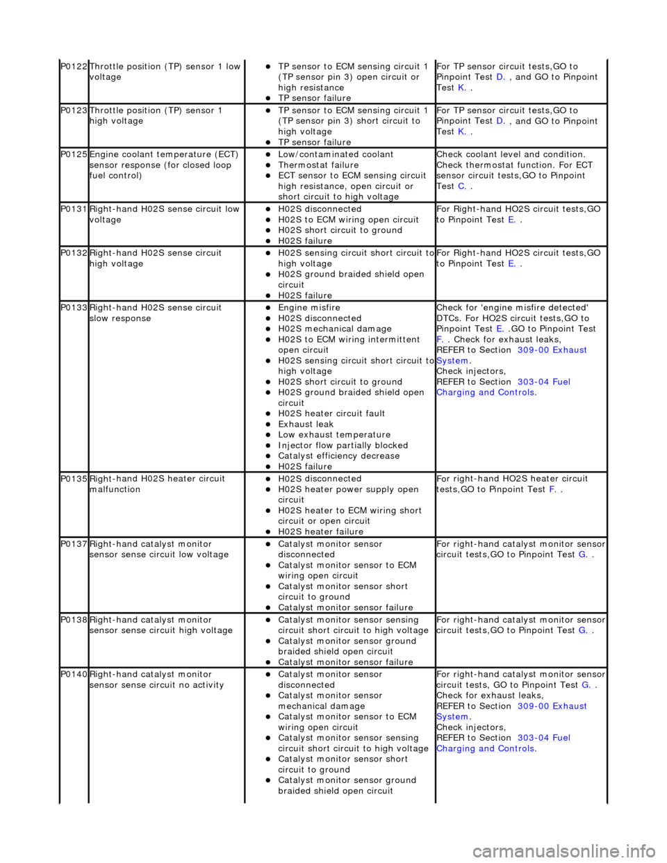
P0122Throttle
position (TP) sensor 1 low
voltage
пЃ¬TP se ns
or to ECM sensing circuit 1
(TP sensor pin 3) open circuit or
high resistance
пЃ¬TP sensor fail
ure
F
o
r TP sensor circ
uit tests,GO to
Pinpoint Test D.
, and GO
to Pinpoint
Test K.
.
P0123Throttl e
position (TP) sensor 1
high voltage
пЃ¬TP se ns
or to ECM sensing circuit 1
(TP sensor pin 3) short circuit to
high voltage
пЃ¬TP sensor fail
ure
F
o
r TP sensor circ
uit tests,GO to
Pinpoint Test D.
, and GO
to Pinpoint
Test K.
.
P0125En
gine coolant temperature (ECT)
sensor response (for closed loop
fuel control)
пЃ¬Low/contaminated coolant пЃ¬Therm o
stat failure
пЃ¬ECT se
ns
or to ECM sensing circuit
high resistance, open circuit or
short circuit to high voltage
Che c
k coolant level and condition.
Check thermostat function. For ECT
sensor circuit tests,GO to Pinpoint
Test C.
.
P0131Right -
hand H02S sense circuit low
voltage
пЃ¬H02 S
disconnected
пЃ¬H0
2S to
ECM wiring open circuit
пЃ¬H0
2S short ci
rcuit to ground
пЃ¬H0
2S fail
ure
F
or R
ight-hand HO2S circuit tests,GO
to Pinpoint Test E.
.
P0132Right-
hand H02S sense circuit
high voltage
пЃ¬H02 S
sensing circuit short circuit to
high voltage
пЃ¬H0 2S groun
d braided shield open
circuit
пЃ¬H0 2S fail
ure
F
or R
ight-hand HO2S circuit tests,GO
to Pinpoint Test E.
.
P0133Right-
hand H02S sense circuit
slow response
пЃ¬Engine m
isfire
пЃ¬H02
S
disconnected
пЃ¬H0
2S mechanical damage
пЃ¬H0
2S to
ECM wiring intermittent
open circuit
пЃ¬H02 S
sensing circuit short circuit to
high voltage
пЃ¬H02S short ci
rcuit to ground
пЃ¬H02S groun
d braided shield open
circuit
пЃ¬H0 2S heater circuit faul
t
пЃ¬Exhaus
t leak
пЃ¬Low e
x
haust temperature
пЃ¬Injector fl
ow parti
ally blocked
пЃ¬Catal
y
st efficiency decrease
пЃ¬H0
2S fail
ure
Chec
k for 'en
gine misfire detected'
DTCs. For HO2S circuit tests,GO to
Pinpoint Test E.
.G
O to Pinpoint Test
F.
. Check for exhaust leaks,
REF
ER to Section 309
-00
Ex
haust
Sy
ste
m
.
Chec k inje
ctors,
REFER to Section 303
-04 Fu
el
Charging and Cont
rols
.
P0135Right
-
hand H02S heater circuit
malfunction
пЃ¬H02 S
disconnected
пЃ¬H0
2S h
eater power supply open
circuit
пЃ¬H0 2S heater to ECM wi
ring short
circuit or open circuit
пЃ¬H0 2S heater fai
lure
F
o
r right-hand HO2S heater circuit
tests,GO to Pinpoint Test F.
.
P0137Right-
hand catalyst monitor
sensor sense circuit low voltage
пЃ¬Catal y
st monitor sensor
disconnected
пЃ¬Catal y
st monitor sensor to ECM
wiring open circuit
пЃ¬Catal y
st monitor sensor short
circuit to ground
пЃ¬Cat a
lyst monitor sensor failure
F
or ri
ght-hand catalyst monitor sensor
circuit tests,GO to Pinpoint Test G.
.
P0138Right -
hand catalyst monitor
sensor sense circuit high voltage
пЃ¬Catal y
st monitor sensor sensing
circuit short circuit to high voltage
пЃ¬Catalyst
monitor sensor ground
braided shield open circuit
пЃ¬Cata
lyst monitor sensor failure
F
or ri
ght-hand catalyst monitor sensor
circuit tests,GO to Pinpoint Test G.
.
P0140Right -
hand catalyst monitor
sensor sense circuit no activity
пЃ¬Catal y
st monitor sensor
disconnected
пЃ¬Catal y
st monitor sensor
mechanical damage
пЃ¬Catal y
st monitor sensor to ECM
wiring open circuit
пЃ¬Catal y
st monitor sensor sensing
circuit short circuit to high voltage
пЃ¬Cataly
st monitor sensor short
circuit to ground
пЃ¬Catalyst
monitor sensor ground
braided shield open circuit
F or ri
ght-hand catalyst monitor sensor
circuit tests, GO to Pinpoint Test G.
.
Check f o
r exhaust leaks,
REFER to Section 309
-00 Ex
haust
Sy
ste
m
.
Chec k inje
ctors,
REFER to Section 303
-04 Fu
el
Charging and Con
t
rols
.
Page 1197 of 2490

пЃ¬Exhaus
t leak
пЃ¬Low e
xhaust temperature
пЃ¬Cat
alyst monitor sensor failure
P0151Le
ft-hand H02S sense circuit low
voltage
пЃ¬H02
S disconnected
пЃ¬H0
2S to ECM wiring open circuit
пЃ¬H0
2S short circuit to ground
пЃ¬H0
2S failure
F
or left-hand HO2S circuit tests, GO
to Pinpoint Test H.
.
P0152Le
ft-hand H02S sense circuit high
voltage
пЃ¬H02
S sensing circuit short circuit to
high voltage
пЃ¬H0
2S ground braided shield open
circuit
пЃ¬H0
2S failure
F
or left-hand HO2S circuit tests,GO to
Pinpoint Test H.
.
P0153Le
ft-hand H02S sense circuit slow
response
пЃ¬Engine
misfire
пЃ¬H02
S disconnected
пЃ¬H0
2S mechanical damage
пЃ¬H0
2S to ECM wiring intermittent
open circuit
пЃ¬H02
S sensing circuit short circuit to
high voltage
пЃ¬H0
2S short circuit to ground
пЃ¬H0
2S ground braided shield open
circuit
пЃ¬H0
2S heater circuit fault
пЃ¬Exhaus
t leak
пЃ¬Low e
xhaust temperature
пЃ¬Injector fl
ow partially blocked
пЃ¬Catal
yst efficiency decrease
пЃ¬H0
2S failure
Chec
k for 'engine misfire detected'
DTCs. For HO2S circ uit tests, GO to
Pinpoint Test H.
. Check for exhaust
leak
s,
REFER to Section 309
-00
Exhaust
Sy
stem
.
Chec
k injectors,
REFER to Section 303
-04
Fuel
Charging and Con
trols
.
P0155Left-hand H02S heater
circuit
malfunction
пЃ¬H02
S disconnected
пЃ¬H0
2S heater power supply open
circuit
пЃ¬H0
2S heater to ECM wiring short
circuit or open circuit
пЃ¬H0
2S heater failure
F
or left-hand HO2S heater circuit
tests,GO to Pinpoint Test I.
.
P0157Le
ft-hand catalyst monitor sensor
sense circuit low voltage
пЃ¬Catal
yst monitor sensor
disconnected
пЃ¬Catal
yst monitor sensor to ECM
wiring open circuit
пЃ¬Catal
yst monitor sensor short
circuit to ground
пЃ¬Cat
alyst monitor sensor failure
F
or left-hand catalyst monitor sensor
circuit tests,GO to Pinpoint Test J.
.
P0158Le
ft-hand catalyst monitor sensor
sense circuit high voltage
пЃ¬Catal
yst monitor sensor sensing
circuit short circuit to high voltage
пЃ¬Catalyst
monitor sensor ground
braided shield open circuit
пЃ¬Cat
alyst monitor sensor failure
F
or left-hand catalyst monitor sensor
circuit tests,GO to Pinpoint Test J.
.
P0160Le
ft-hand catalyst monitor sensor
sense circuit no activity
пЃ¬Catal
yst monitor sensor
disconnected
пЃ¬Catal
yst monitor sensor
mechanical damage
пЃ¬Catal
yst monitor sensor to ECM
wiring open circuit
пЃ¬Catal
yst monitor sensor sensing
circuit short circuit to high voltage
пЃ¬Catal
yst monitor sensor short
circuit to ground
пЃ¬Catalyst
monitor sensor ground
braided shield open circuit
пЃ¬Exhaus
t leak
пЃ¬Low e
xhaust temperature
пЃ¬Cat
alyst monitor sensor failure
F
or left-hand catalyst monitor sensor
circuit tests,GO to Pinpoint Test J.
.
Check f
or exhaust leaks,
REFER to Section 309
-00
Exhaust
Sy
stem
.
P0171Right
-hand cylinders combustion
too lean
пЃ¬Air
intake leak between MAF senso
r and th
rottle
пЃ¬F
uel filter system blockage
пЃ¬F
uel injector blockage
пЃ¬F
uel pressure regulator failure (low
fuel pressure)
пЃ¬Low f
uel pump output
Check ai
r intake system for leaks,
REFER to Section 303
-1
2 Intake Air
Distribu
tion and Filtering
.
Check the fuel fi
lter,
REFER to Section 310
-01
Fuel Tank
and Lines.
Chec
k the fuel injectors and fuel
Page 1200 of 2490
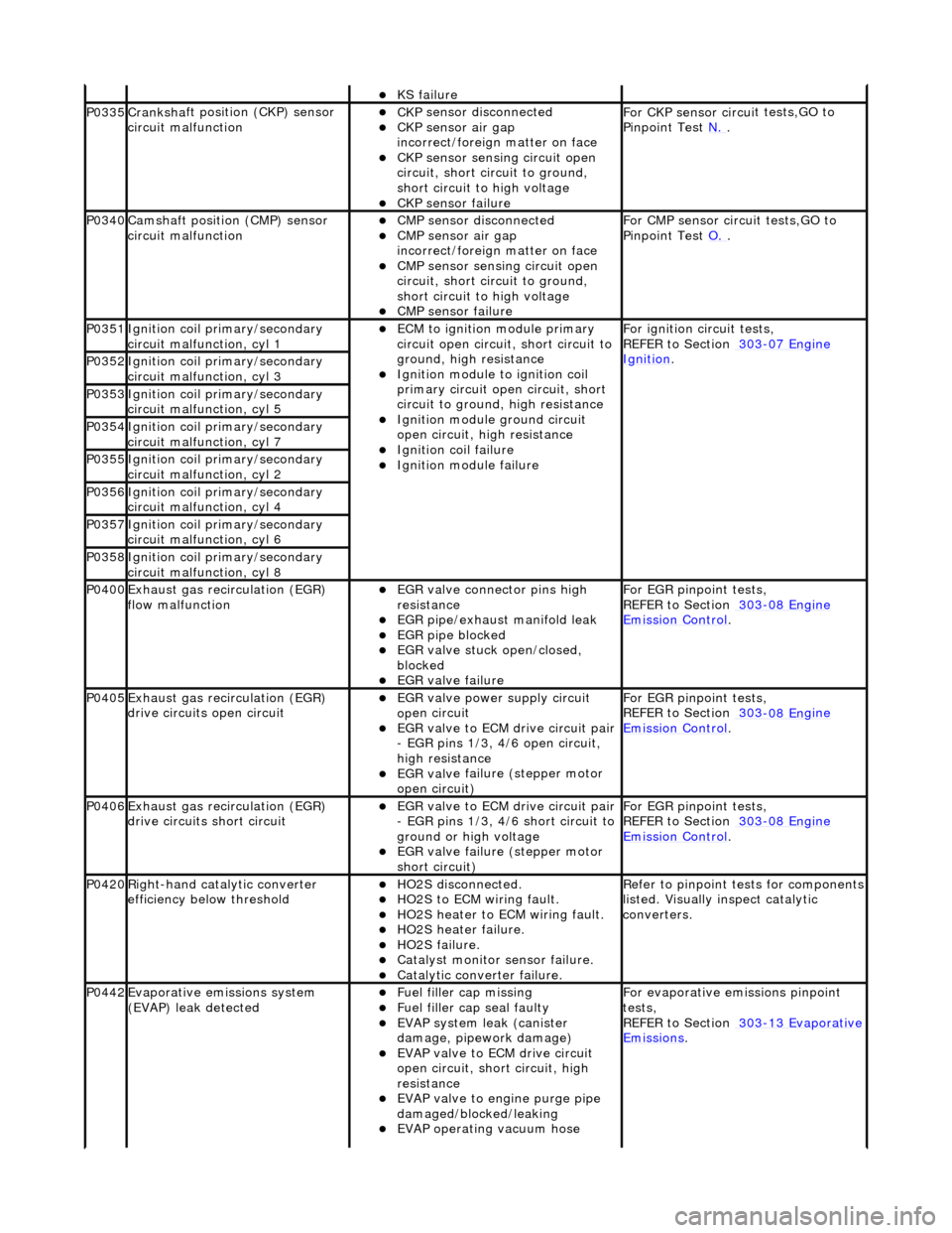
пЃ¬KS fail
ure
P0335Cranksh
a
ft positi
on (CKP) sensor
circuit malfunction
пЃ¬CK P
sensor disconnected
пЃ¬CKP sensor air gap
i
n
correct/foreign matter on face
пЃ¬CKP sensor sen
s
ing circuit open
circuit, short circuit to ground,
short circuit to high voltage
пЃ¬CKP s e
nsor failure
F
or CKP sensor circ ui
t tests,GO to
Pinpoint Test N.
.
P0340Camshaft position
(CMP) sensor
circuit malfunction
пЃ¬CM P
sensor disconnected
пЃ¬CMP sensor air gap
i
n
correct/foreign matter on face
пЃ¬CMP sensor sen
s
ing circuit open
circuit, short circuit to ground,
short circuit to high voltage
пЃ¬CMP s e
nsor failure
F
or CMP sensor circ ui
t tests,GO to
Pinpoint Test O.
.
P0351Igniti
on coil primary/secondary
circuit malfunction, cyl 1
пЃ¬ECM to ignit
ion module primary
circuit open circuit, short circuit to
ground, high resistance
пЃ¬Igniti
on module to ignition coil
primary circuit open circuit, short
circuit to ground, high resistance
пЃ¬Ignition modu le
ground circuit
open circuit, hi gh resistance
пЃ¬Ignition coil fail
ure
пЃ¬Ignition modul
e
failure
F
o
r ignition circuit tests,
REFER to Section 303
-07 En
gine
Ignition. P0352Ignit
i
on coil primary/secondary
circuit malfunction, cyl 3
P0353Ignit i
on coil primary/secondary
circuit malfunction, cyl 5
P0354Ignit i
on coil primary/secondary
circuit malfunction, cyl 7
P0355Ignit i
on coil primary/secondary
circuit malfunction, cyl 2
P0356Ignit i
on coil primary/secondary
circuit malfunction, cyl 4
P0357Ignit i
on coil primary/secondary
circuit malfunction, cyl 6
P0358Ignit i
on coil primary/secondary
circuit malfunction, cyl 8
P0400Exhaus t gas
recirculation (EGR)
flow malfunction
пЃ¬EGR valve c
onnector pins high
resistance
пЃ¬EGR pipe/exhaust manifol
d leak
пЃ¬EGR pipe blocke
d
пЃ¬EGR valve st
uck open/closed,
blocked
пЃ¬EGR valve fai
lure
For EGR
pinpoint t
ests,
REFER to Section 303
-08 En
gine
Emission Control.
P0405Exhaus
t gas
recirculation (EGR)
drive circuits open circuit
пЃ¬EGR valve power supply circuit
o p
en circuit
пЃ¬EGR valve t
o
ECM drive circuit pair
- EGR pins 1/3, 4/6 open circuit,
high resistance
пЃ¬EGR val v
e failure (stepper motor
open circuit)
For EGR pinpoint t
ests,
REFER to Section 303
-08 En
gine
Emissi
on Control.
P0406Exhaus t gas
recirculation (EGR)
drive circuits short circuit
пЃ¬EGR valve t o
ECM drive circuit pair
- EGR pins 1/3, 4/6 short circuit to
ground or high voltage
пЃ¬EGR val v
e failure (stepper motor
short circuit)
For EGR pinpoint t
ests,
REFER to Section 303
-08 En
gine
Emissi
on Control.
P0420Right-
hand catalytic converter
efficiency below threshold
пЃ¬HO2S di
sconnected.
пЃ¬HO2
S
to ECM wiring fault.
пЃ¬HO2
S
heater to ECM wiring fault.
пЃ¬HO2
S
heater failure.
пЃ¬HO2
S
failure.
пЃ¬Cat
a
lyst monitor sensor failure.
пЃ¬Catal
y
tic converter failure.
R
e
fer to pinpoint tests for components
listed. Visually inspect catalytic
converters.
P0442Evaporati v
e emissions system
(EVAP) leak detected
пЃ¬Fue l
filler cap missing
пЃ¬Fu
el filler cap seal faulty
пЃ¬EVAP system
leak (can
ister
damage, pipework damage)
пЃ¬EVAP v a
lve to ECM drive circuit
open circuit, short circuit, high
resistance
пЃ¬EVAP valve to engine pu rge pipe
damaged/blocked/leaking
пЃ¬EVAP ope r
ating vacuum hose
F
or evaporati
ve emissions pinpoint
tests,
REFER to Section 303
-1 3
Evaporative
Emissi
ons
.