body mounting JAGUAR X308 1998 2.G Owner's Manual
[x] Cancel search | Manufacturer: JAGUAR, Model Year: 1998, Model line: X308, Model: JAGUAR X308 1998 2.GPages: 2490, PDF Size: 69.81 MB
Page 795 of 2490
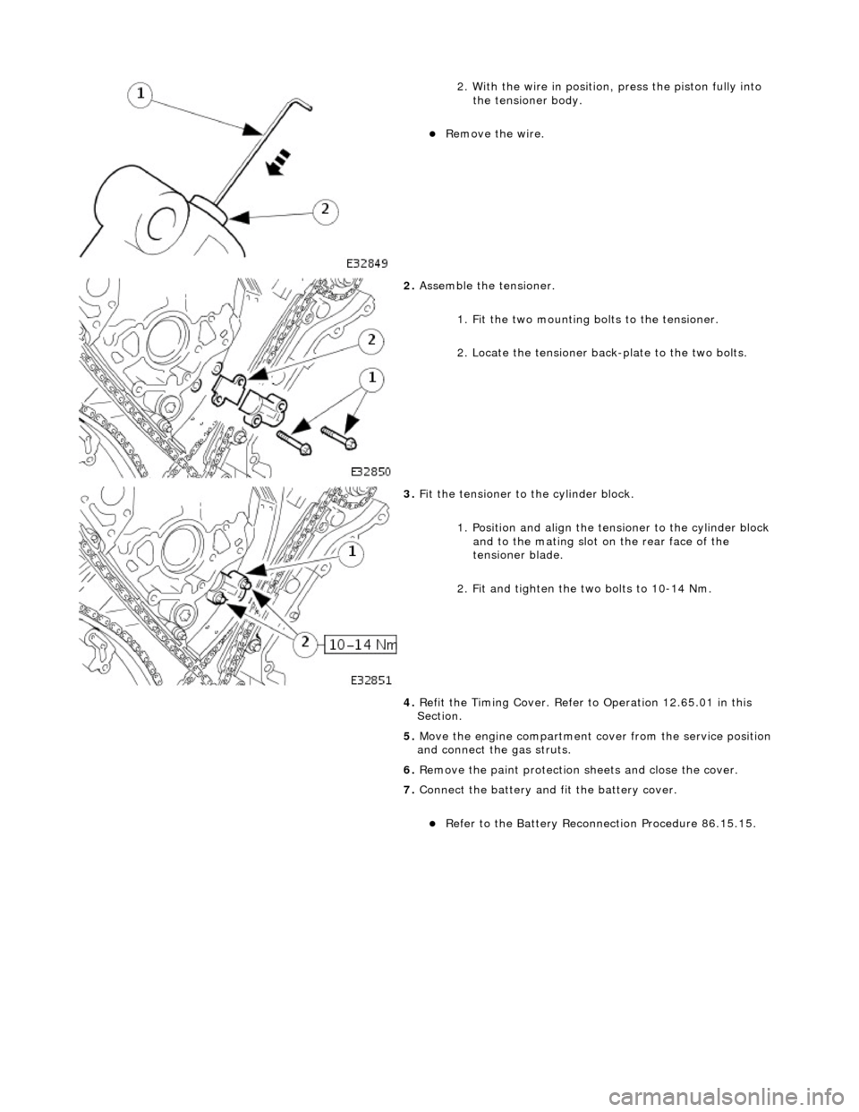
2. With the wire in position, press the piston fully into the tensioner body.
Remove the wire.
2. Assemble the tensioner.
1. Fit the two mounting bolts to the tensioner.
2. Locate the tensioner back-plate to the two bolts.
3. Fit the tensioner to the cylinder block.
1. Position and align the tensioner to the cylinder block and to the mating slot on the rear face of the
tensioner blade.
2. Fit and tighten the two bolts to 10-14 Nm.
4. Refit the Timing Cover. Refer to Operation 12.65.01 in this
Section.
5. Move the engine compartment co ver from the service position
and connect the gas struts.
6. Remove the paint protection sheets and close the cover.
7. Connect the battery and fit the battery cover.
Refer to the Battery Reconnection Procedure 86.15.15.
Page 797 of 2490
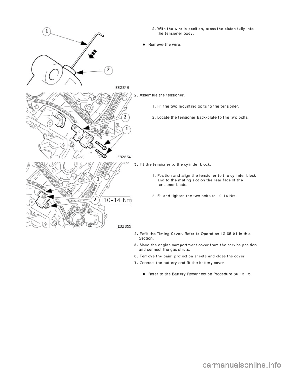
2. With the wire in position, press the piston fully into the tensioner body.
Remove the wire.
2. Assemble the tensioner.
1. Fit the two mounting bolts to the tensioner.
2. Locate the tensioner back-plate to the two bolts.
3. Fit the tensioner to the cylinder block.
1. Position and align the tensioner to the cylinder block and to the mating slot on the rear face of the
tensioner blade.
2. Fit and tighten the two bolts to 10-14 Nm.
4. Refit the Timing Cover. Refer to Operation 12.65.01 in this
Section.
5. Move the engine compartment co ver from the service position
and connect the gas struts.
6. Remove the paint protection sheets and close the cover.
7. Connect the battery and fit the battery cover.
Refer to the Battery Reconnection Procedure 86.15.15.
Page 909 of 2490

1. Remove the nut which secures the selector lever to
the transmission cross shaft.
2. Remove the selector cable abutment bolts.
3. Disconnect the selector arm from the cross shaft.
67. Loosen the bolt which secures the engine rear mounting
rubber to the transmission.
68. Position a transmission jack e.g. Epco V100 and raise the
support bed of the jack to take the weight of the transmission.
Fit and adjust the chains to secure the transmission to the jack.
69. Remove the engine rear mounting assembly.
Remove the mounting centre bolt.
Remove the four bolts which secure the crossmember to
the body.
Remove the crossmember and mounting assembly.
70. Release the engine and tran smission assembly from the
engine compartment.
Take the weight of the engine / transmission with the
hoist and move it towards th e front of the vehicle.
Lower the transmission jack slightly to release the
securing chains. Remove the ja ck from below the vehicle.
Page 912 of 2490

Align th
e engine front mountings and fit the securing nuts.
Tighte
n to the stated torque value.
3. Operate the crane controls and the ramp simultaneously (with
assistance) to raise the vehicle to a convenient working height.
4. Po
sition the transmission jack and raise it to take the weight of
the transmission. Fit and adjust the chains to secure the
transmission to the jack.
5. Fit th
e engine rear mounting bracket.
Fi
t the four bolts which secu
re the crossmember to the
body.
Fi t t
he bolt which secures the
engine rear mounting rubber
to the transmission.
6. Tigh ten th
e rear mounting bolts
to the stated torque figure.
7. Release and remove the transmission jack.
8. Operate the crane controls and the ramp simultaneously (with
assistance) to lower the vehicle to a convenient working height.
9. Lower th e cran
e and remove th
e chain assembly and lifting
eyes.
Page 916 of 2490

3. Conne
ct the brake servo hose.
26. Conne
ct the P.I. harness to the engine management
harness.
1. Reposition the engi ne management harness
connector to the bracket.
2. Fit the nut which secures the engine management harness connector to the mounting bracket.
3. Connect the connectors.
4. Fit the bolt which secures the P.I. harness connector to the engine management harness.
27 . Conne
ct the transmission rotary
switch harness connector.
Re
position and connect the harness.
28 . Con
nect the throttle cable.
1. Fit the bolts which secure the abutment bracket to the throttle body. Tighten to 4-6 Nm.
2. Rotate the butterfly actuator cam and connect the cable. Reposition the cable into the cam.
Re
move any tape or plastic
strap which was fitted when
disconnecting the cable abutment.
29. Connect the pipes to the purge valve.
1. Connect the part load breather hose.
2. Fit the clip which secures the part load breather hose
to the purge valve.
Page 929 of 2490

The cooling
pack incorporates the radiator a
ssembly with integral transmission oil cool er (located in the radiator outlet tank),
an air conditioning condenser, and the cooling fans and cowl assembly.
The cooling pack on supercharged vehicles is the same as described above, but with the addition of a charge air cooler
coolant radiator located in front of the condenser.
Radiator Mounti
ng/Retention
T
he radiator is mounted on four rubber mounts, one on each
end of the upper and lower horizontal face. The two lower
mountings are supported on two isolated brackets mounted on the body; the lower cradle assembly has subsequently been
deleted.
A closing panel made from polypropylene, which retains the radiat or assembly, fits over the top of the radiator and is bolted
to the vehicle top panel.
Coolant Hoses - Engine
Page 1067 of 2490
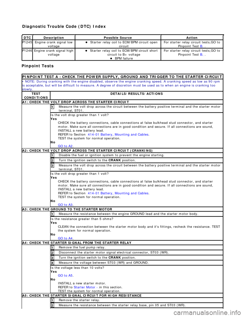
Pinpoint Tests
DT
C
De
scription
Possib
le Source
Acti
on
P1245Engine
crank signal low
voltage
Starter relay
coil to
ECM/BPM circuit open
circuit
F
or starter relay circuit tests,GO to
Pinpoint Test B.
.
P1246Engine
crank signal high
voltage
Starter relay
coil to ECM/BPM circuit short
circuit to B+ voltage
B
PM failure
F
or starter relay circuit tests,GO to
Pinpoint Test B.
.
P
INPOINT TEST A : CHECK THE
POWER SUPPLY, GROUND AND TRI GGER TO THE STARTER CIRCUIT
•
NOTE: During cranking with the engine disabled, observe the engine cranking speed. A cranking speed as low as 90 rpm
is acceptable, but will be difficult to measure. A degree of discretion must be used as to when an engine is cranking too
slowly.
TE
ST
CONDITIONS
D
ETAILS/RESULTS/ACTIONS
A1: CHECK
THE VOLT DROP AC
ROSS THE STARTER CIRCUIT
M
easure the volt drop across the circuit between the battery positive terminal and the starter motor
terminal, ST01.
1
Is the vol
t drop greater than 1 volt?
Yes CHECK the battery connections, cable connections at false bulkhead stud connector, and starter
motor. Make sure all connections are in good co ndition and secure. If all connections are sound,
INSTALL a new battery lead.
REFER to Section 414
-0
1 Battery, Mounting and Cables
.
TEST the system
for normal operation.
No GO to A2
.
A2: CHECK
THE VOLT DROP ACROSS
THE STARTER CIRCUIT (CRANKING)
Di
sable the fuel or ignition system to prevent the engine starting.
1
Turn the ignition swi
tch to the CRANK
position.
2
M
easure the volt drop across the circuit between the battery positive terminal and the starter motor
terminal, ST01.
3
Is the vol
t drop greater than 1 volt?
Yes CHECK the battery connections, cable connections at false bulkhead stud connector, and starter
motor. Make sure all connections are in good co ndition and secure. If all connections are sound,
INSTALL a new battery lead.
REFER to Section 414
-0
1 Battery, Mounting and Cables
.
TEST the system
for normal operation.
No GO to A3
.
A3:
CHECK THE GROUND TO THE STARTER MOTOR
Meas
ure the resistance between the engine GROUND lead and the starter motor body.
1
Is th
e resistance greater than 5 ohms?
Yes CLEAN the connection between the starter motor body and it's fittings, recheck the resistance. TEST
the system for normal operation.
No GO to A4
.
A4
: CHECK THE STARTER SIGNAL FROM THE STARTER RELAY
R
emove the fuel pump relay.
1
Di
sconnect the starter motor signal
electrical connector, ST03 (WR).
2
Turn the ignition swi
tch to the CRANK
position.
3
M
easure the voltage between ST03 (WR) and GROUND.
4
Is th
e voltage less than 10 volts?
Yes GO to A5
.
No
INSTALL a new starter motor.
REFER to Starter Motor
-
in t
his section.
TEST the system for normal operation.
A5
: CHECK THE STARTER SIGNAL CIRCUIT FOR HIGH RESISTANCE
R
emove the starter relay.
1
Meas
ure the resistance between the st
arter relay base, pin 05 and ST03 (WR).
2
Diagnostic Trouble Code (D
TC) Index
Page 1106 of 2490
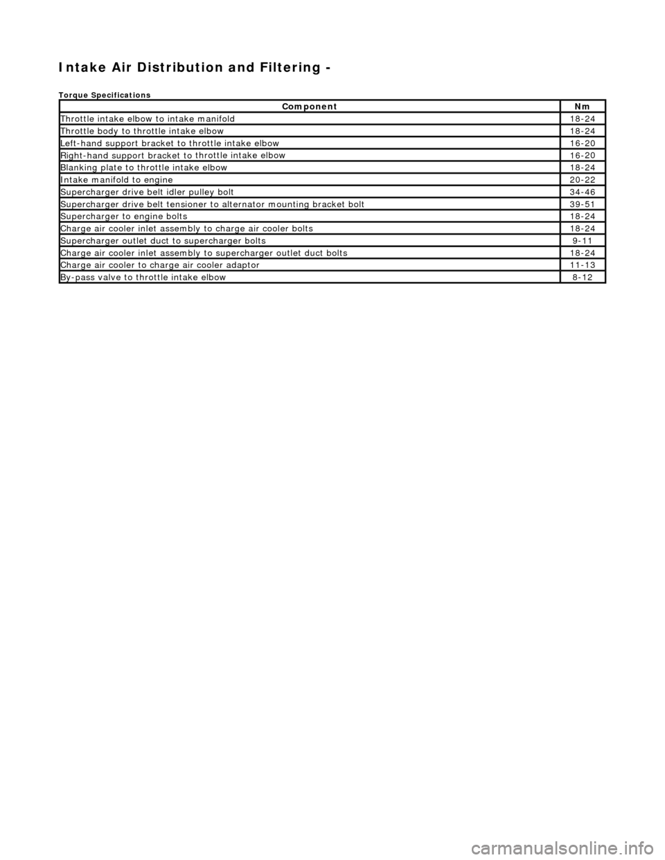
Intake Air Distribution and Filtering -
Torque Specificat
ions
Comp
onent
Nm
Thr
o
ttle intake elbow to intake manifold
18
-
24
Thro
tt
le body to throttle intake elbow
18
-
24
Left-hand support
bracket to
th
rottle intake elbow
16
-
20
Right-hand support
bracket to
throttle intake elbow
16
-
20
B
l
anking plate to throttle intake elbow
18
-
24
Inta
k
e manifold to engine
20
-
22
Supe
rcharger
drive belt idler pulley bolt
34
-
46
Supercharger
drive belt te
nsioner to alternator mounting bracket bolt
39
-
51
Supercharger
to eng
ine bolts
18
-
24
Charge air cooler in
let assembly to charge ai
r cooler bolts
18
-
24
Supercharger
outlet duct to supercharger bolts9-1
1
Charge air cooler in
let assembly to superchar
ger ou
tlet duct bolts
18-
24
Charge air cool
er to charge
air cooler adaptor
11
-
13
B
y
-pass valve to throttle intake elbow
8-
1
2
Page 1117 of 2490
I
nstallation
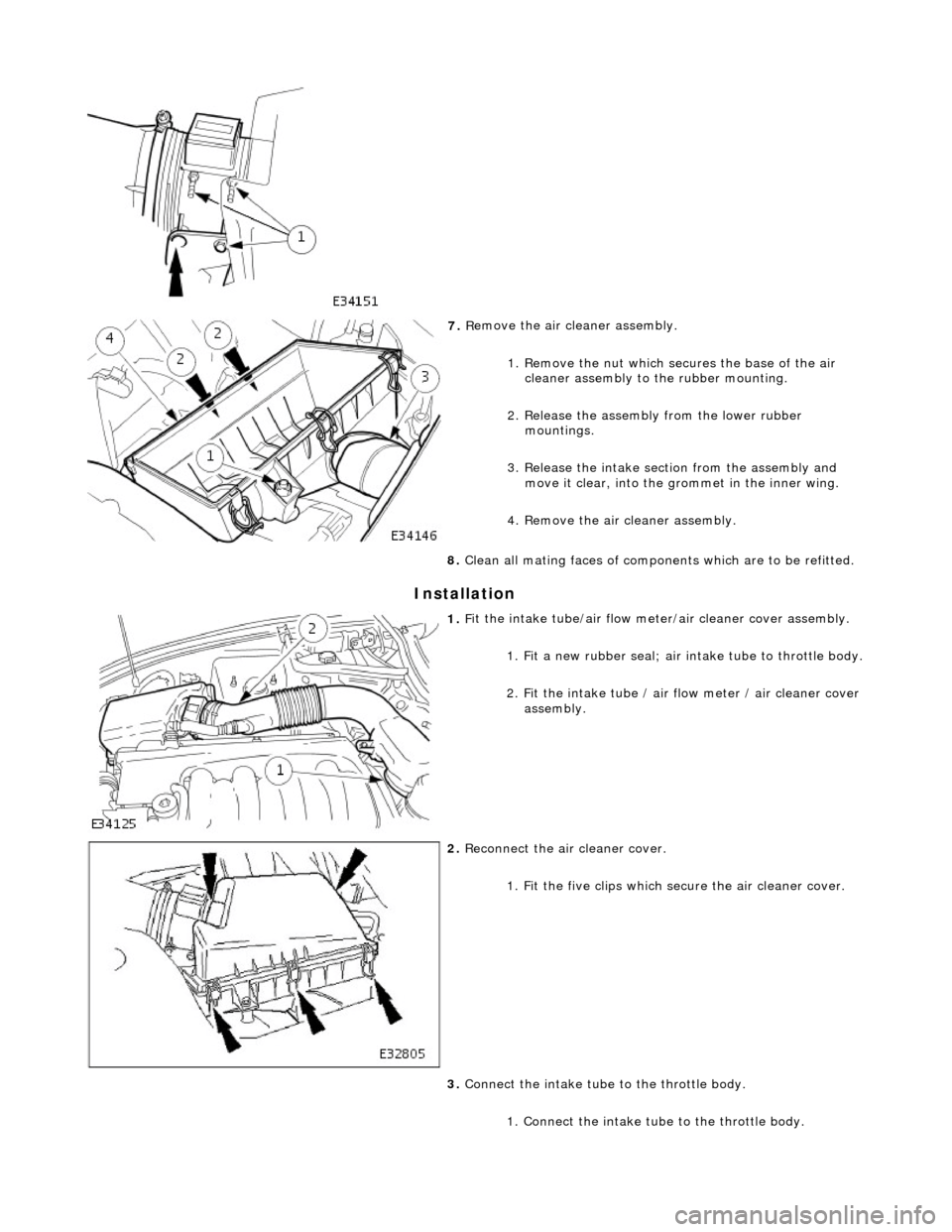
7.
R
emove the air cleaner assembly.
1. Remove the nut which se cures the base of the air
cleaner assembly to the rubber mounting.
2. Release the assembly from the lower rubber mountings.
3. Release the intake section from the assembly and move it clear, into the grommet in the inner wing.
4. Remove the air cleaner assembly.
8. Clean all mating faces of compon ents which are to be refitted.
1. F
it the intake tube/air flow meter/air cleaner cover assembly.
1. Fit a new rubber seal; air in take tube to throttle body.
2
. Fit the intake tube / air
flow meter / air cleaner cover
assembly.
2. R
econnect the air cleaner cover.
1. Fit the five clips which secure the air cleaner cover.
3. Connect the intake tube to the throttle body.
1. Connect the intake tube to the throttle body.
Page 1155 of 2490
T
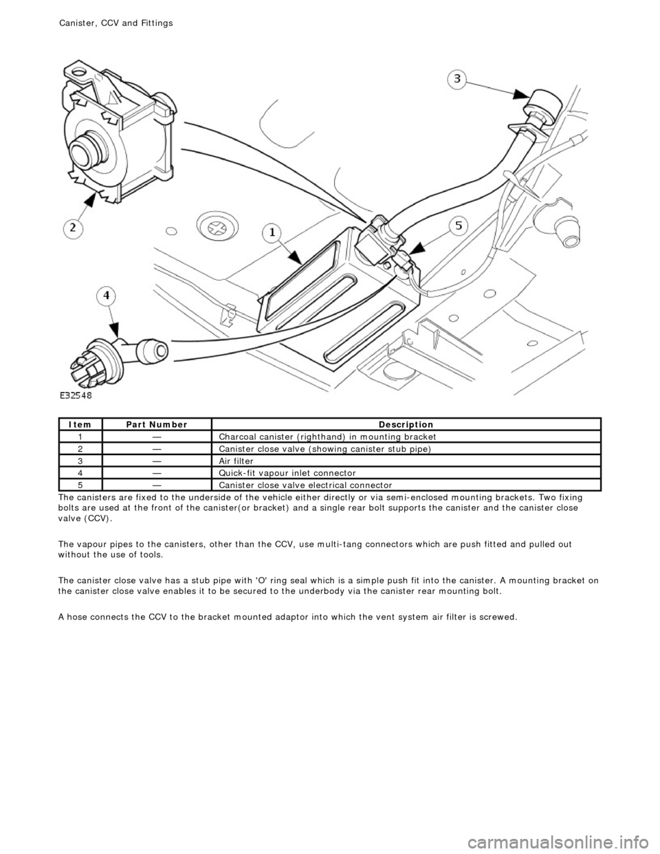
he canisters are fixed to the underside of the vehicle either
directly or via semi-enclosed mounting brackets. Two fixing
bolts are used at the front of the canister(or bracket) and a single rear bolt supports the canister and the canister close
valve (CCV).
The vapour pipes to the canisters, other than the CCV, use multi-tang connectors which are push fitted and pulled out
without the use of tools.
The canister close valve has a stub pipe with 'O' ring seal wh ich is a simple push fit into the canister. A mounting bracket on
the canister close valve enables it to be secured to the underbody via the canister rear mounting bolt.
A hose connects the CCV to the bracket mounted adaptor into which the vent system air filter is screwed.
It
em
Par
t Number
De
scription
1—C
harcoal canister (righthand) in mounting bracket
2—Cani
ster close valve (showi
ng canister stub pipe)
3—Ai
r filter
4—Q
uick-fit vapour inlet connector
5—Cani
ster close valve electrical connector
Canister, CCV an
d Fittings