body mounting JAGUAR X308 1998 2.G User Guide
[x] Cancel search | Manufacturer: JAGUAR, Model Year: 1998, Model line: X308, Model: JAGUAR X308 1998 2.GPages: 2490, PDF Size: 69.81 MB
Page 197 of 2490

With
draw the hub carrier and support on a block of wood.
9. CAUTI
ON: Note the position of
the shims during removal.
They must be returned to th eir original position during
installation.
Noting their positions, remove the shim from each end of the
pivot pin sleeve.
10
.
WARNINGS:
ENSURE THE SPECIAL TOOLS ARE POSITIONED
DIAMETRICALLY OPPOSITE ON THE SPRING AND THE ARMS ARE
CORRECTLY SEATED .
WHEN COMPRESSING THE SPRING, TIGHTEN THE
SPECIAL-TOOL ADJUSTMENT BOLTS EVENLY.
Compress the spring.
Install and alig
n the special
tools 204-179 diametrically
opposite on the spring.
Eve
nly tighten the special tool tensioning bolts to
compress the spring.
11
.
Remove the shock absorber to wishbone mounting nut and
bolt.
12. Remove the nuts securing th e shock absorber and spring
upper mounting to the body.
Page 204 of 2490
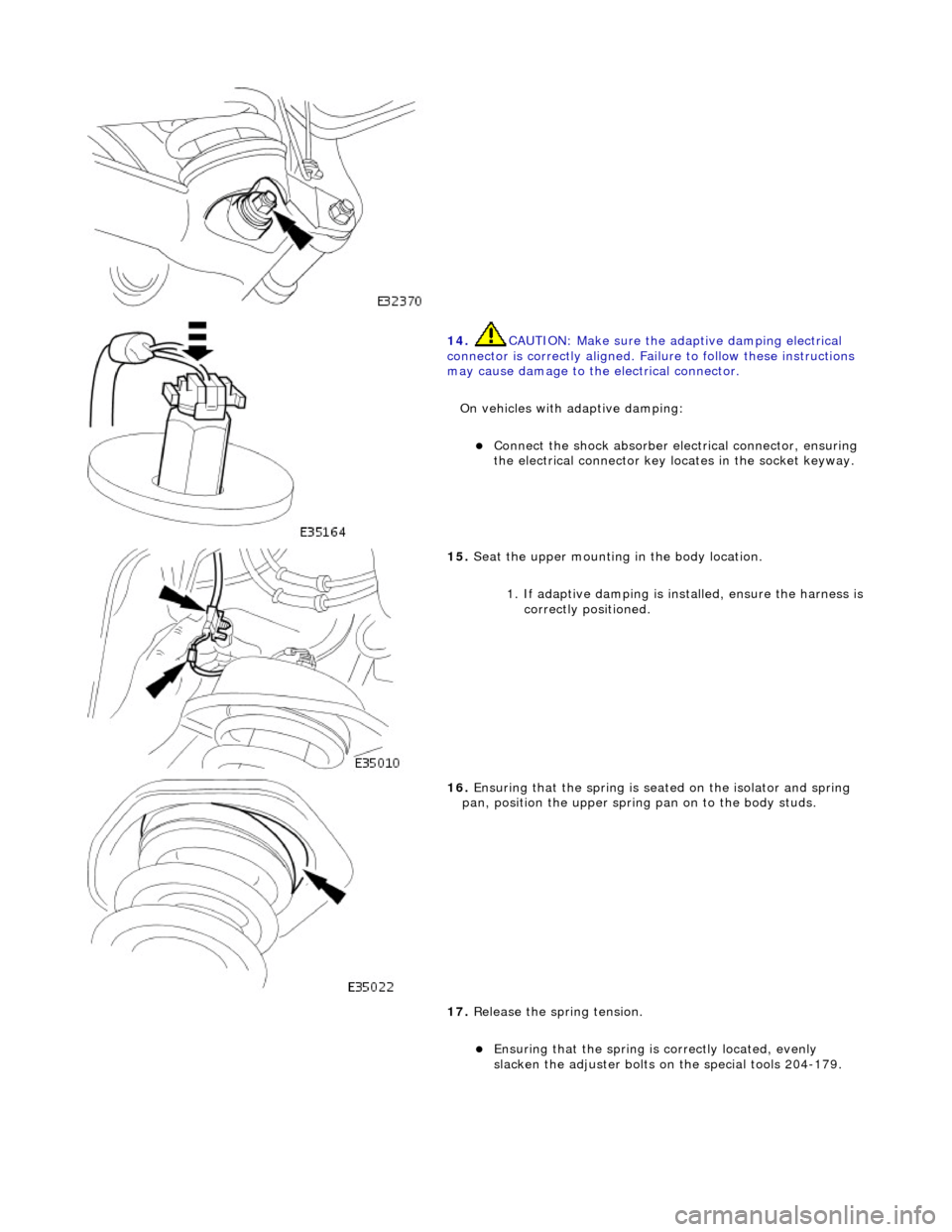
14. CAUTI
ON: Make sure the adaptive damping electrical
connector is correctly aligned. Failu re to follow these instructions
may cause damage to the electrical connector.
On vehicles with adaptive damping:
Conne ct
the shock absorber elec
trical connector, ensuring
the electrical connector key locates in the socket keyway.
15 . Seat
the upper mounting in the body location.
1. If adaptive damping is installed, ensure the harness is
correctly positioned.
16 . Ensuri
ng that the spri
ng is seated on the isolator and spring
pan, position the u pper spring pan on to the body studs.
17. Release the spring tension.
Ensuring that the spri
ng is
correctly located, evenly
slacken the adjuster bolts on the special tools 204-179.
Page 218 of 2490

Rear Suspension - Stabilizer Bar Mounting Frame
Remo
val and Installation
Remov
a
l
CAUTI
O
N: Replacement of
nuts and bolts: Various thread-locking devices are used on nuts and bolts throughout the
vehicle. These devices restrict the number of times a nut or bolt can be used. See section 100-00 for information.
1. Ra
ise rear of vehicle and support
on stands. Refer to Section
100-02.
2. Support rear suspensio
n.
Posit
i
on a piece of wood under rear edge of suspension
unit.
Position an d
raise a jack
under wood to support
suspension unit.
3. Re
move monostrut lowe
r nuts and bolts.
4. Remove m
onostrut upper mounting
to body bracket securing
bolts.
5. Remove monostrut.
Lower rear edg
e
of suspension unit just sufficient for
access.
Exercising care to avoid dama ging fuel fil
ler neck drain
pipe, lift and withdraw monost rut from rear suspension.
Page 280 of 2490
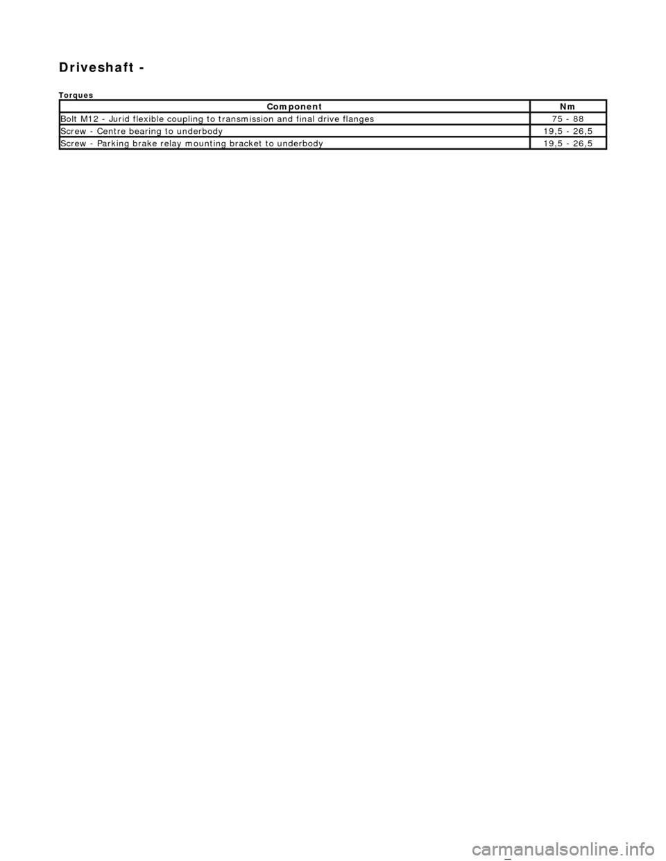
Driveshaft -
Torques
Comp
onent
Nm
Bol
t
M12 - Jurid flexible coupling to
transmission and final drive flanges
75
-
88
Screw
-
Centre bearing to underbody
19
,5
- 26,5
Screw
-
Parking brake relay mounting bracket to underbody
19
,5
- 26,5_
Page 390 of 2490
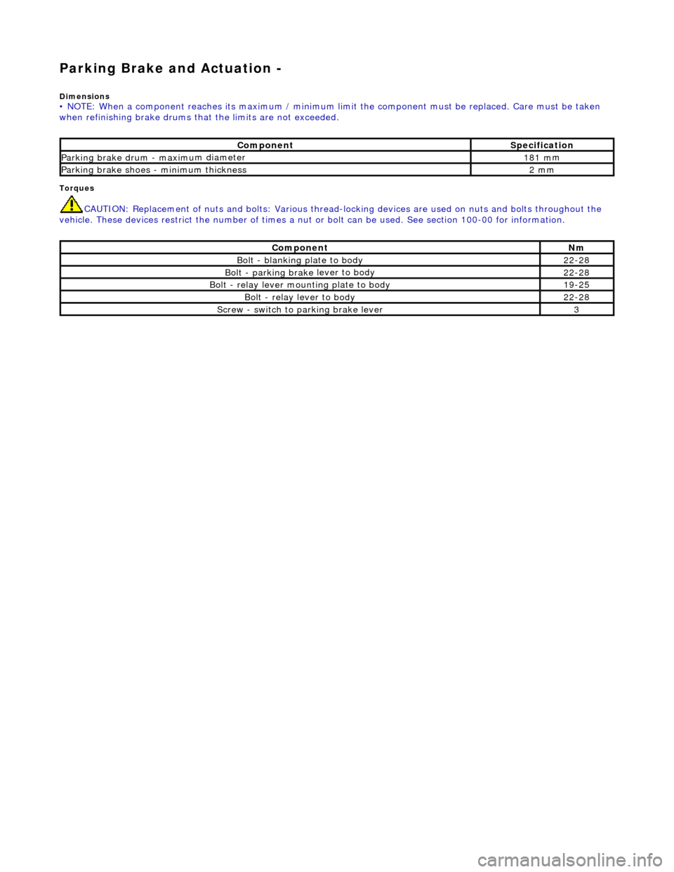
Parking Brake and Actuation -
Dim
ensions
• NO
TE: When a component reaches its maximum / minimum limit the component must be replaced. Care must be taken
when refinishing brake drums that the limits are not exceeded.
Torq ues
CAUTI
O
N: Replacement of
nuts and bolts: Various thread-locking devices are used on nuts and bolts throughout the
vehicle. These devices restrict the number of times a nut or bolt can be used. See section 100-00 for information.
Com p
onent
S
p
ecification
Parkin
g brake drum - maximu
m diameter
1
81 m
m
Parkin
g brake sh
oes - minimum thickness
2 m
m
Com p
onent
Nm
Bolt - blan
k
ing plate to body
22
-28
Bolt - park ing brake
lever to body
22
-28
Bolt - r
elay lever mounting plate to body
19
-25
Bo lt
- relay lever to body
22
-28
Screw - switch to parking brake lever3
Page 478 of 2490
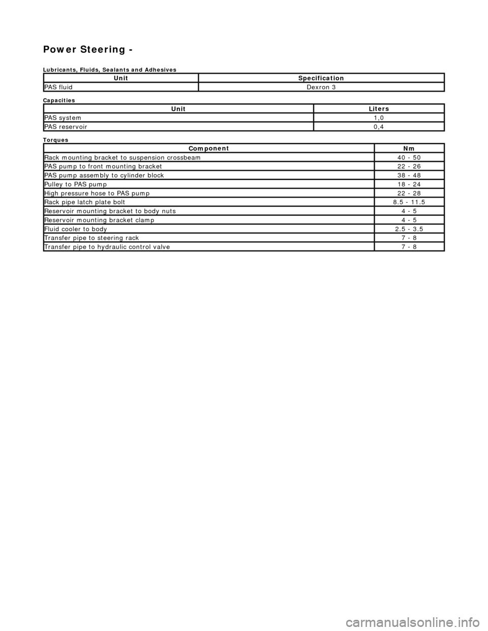
Power Steering -
Lubric
ants, Fluids, Sealants and Adhesives
Capacities
Torques
UnitSp
ecification
PAS flu
i
d
De
xr
on 3
UnitLi
t
ers
PAS syste
m1,0
PAS reservoi
r0,4
Com p
onent
Nm
Rac
k
mountin
g brac
ke
t to suspension crossbeam
40
- 50
PAS pump to front mounti
ng bracket
22
-
26
P
AS pu
mp assembly to cylinder block
38
-
48
Pul
l
ey to PAS pump
18
-
24
Hi
gh pressure hose to PAS pump22 -
28
Rack
pipe latch plate bolt8.5 -
11.5
R
e
servoir mounting bracket to body nuts
4 -
5
R
e
servoir mounting bracket clamp
4 -
5
Fluid cooler to body2.
5 -
3.5
Transfer pipe
to steering rack7 -
8
Transfer pipe
to hydraulic con
trol valve
7 -
8
Page 485 of 2490
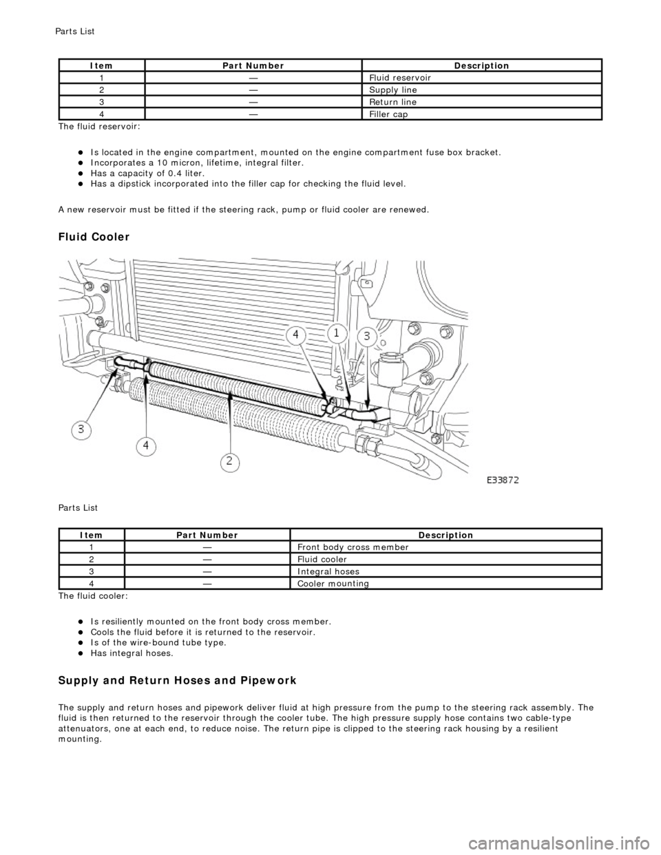
The fluid reservo
ir:
Is lo
cated in the engine compartment, mounted on the engine compartment fuse box bracket.
Incorporates
a 10 micron, li
fetime, integral filter.
Has a cap
acity of 0.4 liter.
Has a dipsti
ck incorporated into the filler cap for checking the fluid level.
A new reservoir must be fitted if the steering rack, pump or fluid cooler are renewed.
Fluid C
ooler
P
arts List
The fluid cooler:
Is
resiliently mounted on th
e front body cross member.
Coo
ls the fluid before it is
returned to the reservoir.
Is
of the wire-bound tube type.
Has i
ntegral hoses.
Supply and Return Hoses a
nd Pipework
The supply and return h
oses and
pipework deliver fluid at high pressure from the pump to th e steering rack assembly. The
fluid is then returned to th e reservoir through the cooler tube. The high pressure supply hose contains two cable-type
attenuators, one at each end, to reduce nois e. The return pipe is clipped to the steering rack housing by a resilient
mounting.
It
em
Par
t Number
De
scription
1—Fl
uid reservoir
2—Supply line
3—R
eturn line
4—Fi
ller cap
It
em
Par
t Number
De
scription
1—Front body cross member
2—F
luid cooler
3—Inte
gral hoses
4—Cooler m
ounting
P
arts List
Page 530 of 2490
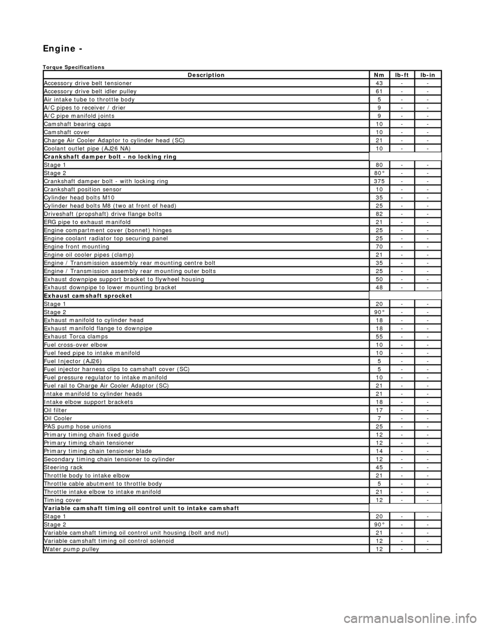
Engi
ne -
Torqu
e Specifications
De
s
cription
Nmlb
-
ft
lb
-
in
A
ccessory
drive belt tensioner
43--
A
ccessory
drive belt idler pulley
61--
Air in
ta
ke tube to throttle body
5--
A/C
pipes t
o receiver / drier
9--
A/C pipe m
anifold joints
9--
Camsh
aft bearin
g caps10--
Ca
msh
aft cove
r10--
Ch
arge Air Co
oler Adaptor to cylinder head (SC)
21--
Co
olan
t outlet pipe (AJ26 NA)
10--
Cran
kshaft damper bolt - no lockin
g ring
St
ag
e 1
80--
Stag
e 2
80°--
C
r
ankshaft damper bolt - with locking ring
37
5--
Cra
nkshaft position sensor
10--
Cy
li
nder head bolts M10
35--
Cy
lin
der head bolts M8 (two at front of head)
25--
Driv
es
haft (propshaft) drive flan
ge bo
l
ts
82--
ERG p
i
pe to exhaust manifold
21--
Engi
ne compartment cover (bonnet) hinges
25--
En
gine
coolant radiator top securing panel
25--
E
ng
ine front mounting
70--
En
gine
oil cooler pipes (clamp)
21--
En
gi
ne / Transmission assembly rear mounting centre bolt
35--
En
gi
ne / Transmission assembly rear mounting outer bolts
25--
Ex
ha
ust downpipe support bracket to flywheel housing
50--
Ex
ha
ust downpipe to lower mounting bracket
48--
E
x
haust camshaft sprocket
St
age 120--
Stage 290 °--
Ex
haust manifold to cylinder head
18--
Ex
ha
ust manifold flange to downpipe
18--
E
x
haust Torca clamps
55--
Fuel cross-over elbo
w
10--
Fu
el f
eed pipe to intake manifold
10--
Fuel
Injector (AJ
26)
5--
Fuel
injector ha
rness clips to camshaft cover (SC)
5--
Fu
el p
ressure re
gu
l
ator to intake manifold
10--
F
u
el rail to Char
ge
A
ir Cooler Adaptor (SC)
21--
In
ta
ke manifold to cylinder heads
21--
Inta
ke elbow support brackets
18--
Oil f
i
lter
17--
Oil C
o
oler
7--
P
AS pu
mp hose unions
25--
P
r
imary timing chain fixed guide
12--
P
r
imary timing chain tensioner
12--
Pr
imary timing chain tensioner blade
14--
S
e
condary timing chain tensioner to cylinder
12--
S
t
eerin
g ra
ck45--
Thro
ttle body to intake elbow
21--
Th
ro
ttle cable abutment to throttle body
5--
Th
ro
ttle intake elbow to intake manifold
21--
Ti
mi
ng cover
12--
Variable camshaft t
i
ming oil control unit to intake camshaft
St
ag
e 1
20--
St
ag
e 2
90
°--
Var
iable camshaft timing oil control unit housing (bolt and nut)
21--
Va
ria
ble camshaft timi
ng oil control solenoid
12--
Wa
ter pump pulley
12--
Page 623 of 2490

Re
position the sprocket (and the VVT unit) for the most advantageous
position for use of the tool.
R
emove the tool.
25
.
Install the primary timing chain.
R
eposition the VVT unit forwards on the cam journal (do not rotate it)
to allow the chain to cl ear the head casting. Disconnect the primary
chain from the Ty-strap.
1. Install the primary chain to position over the crankshaft sprocket and the VVT unit sprocket. There mu st be no slack on the drive
side of the primary chain and the VVT unit must not be rotated on
the camshaft.
26
.
Install the primary chain tensioner blade.
1. Position the tensioner blade to the cylinder block.
2. Install the retaining / pivot bolt and tighten it to 14 Nm.
27
.
Push the primary chain tensioner piston into the body to provide clearance
for installing.
1. Insert a thin rigid wire through the hole in the end of the tensioner
piston to displace the ball from the non-return valve seat.
2. With the wire in position, press the piston fully into the tensioner body.
Re
move the wire.
28
.
Assemble the tensioner.
1. Install the two mounting bolts to the tensioner.
2. Locate the tensioner back-plate to the two bolts.
29. Install the tensioner to the cylinder block.
1. Position and align the tensioner to the cylinder block and to the mating slot on the rear face of the tensioner blade.
2. Install and tighten the two bolts to 12 Nm.
Page 638 of 2490
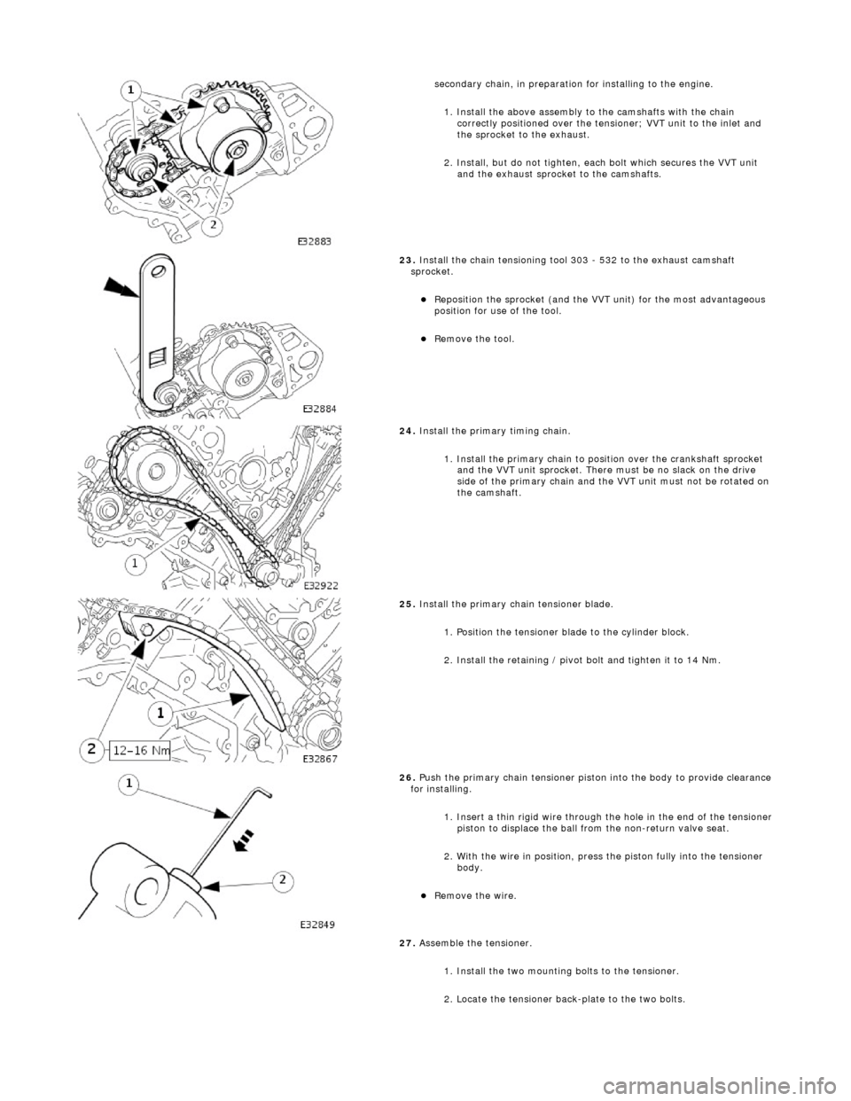
se
condary chain, in preparation for installing to the engine.
1. Install the above assembly to the camshafts with the chain correctly positioned over the tensioner; VVT unit to the inlet and
the sprocket to the exhaust.
2. Install, but do not tighten, each bolt which secures the VVT unit and the exhaust sprocket to the camshafts.
23 .
Install the chain t
ensioning tool 303 - 532 to the exhaust camshaft
sprocket.
Re p
osition the sprocket (and the VVT unit) for the most advantageous
position for use of the tool.
Re
move the tool.
24 . Install the
primary timing chain.
1. Install the primary chain to position over the crankshaft sprocket and the VVT unit sprocket. There mu st be no slack on the drive
side of the primary chain and the VVT unit must not be rotated on
the camshaft.
25 . Install the pri
mary chain tensioner blade.
1. Position the tensioner blade to the cylinder block.
2. Install the retaining / pivot bolt and tighten it to 14 Nm.
26 . P
ush the primary chain tensioner piston into the body to provide clearance
for installing.
1. Insert a thin rigid wire through the hole in the end of the tensioner
piston to displace the ball from the non-return valve seat.
2. With the wire in position, press the piston fully into the tensioner body.
Rem
ove the wire.
27. Assemble the tensioner.
1. Install the two mounting bolts to the tensioner.
2. Locate the tensioner back-plate to the two bolts.