diagram JAGUAR X308 1998 2.G Repair Manual
[x] Cancel search | Manufacturer: JAGUAR, Model Year: 1998, Model line: X308, Model: JAGUAR X308 1998 2.GPages: 2490, PDF Size: 69.81 MB
Page 1530 of 2490
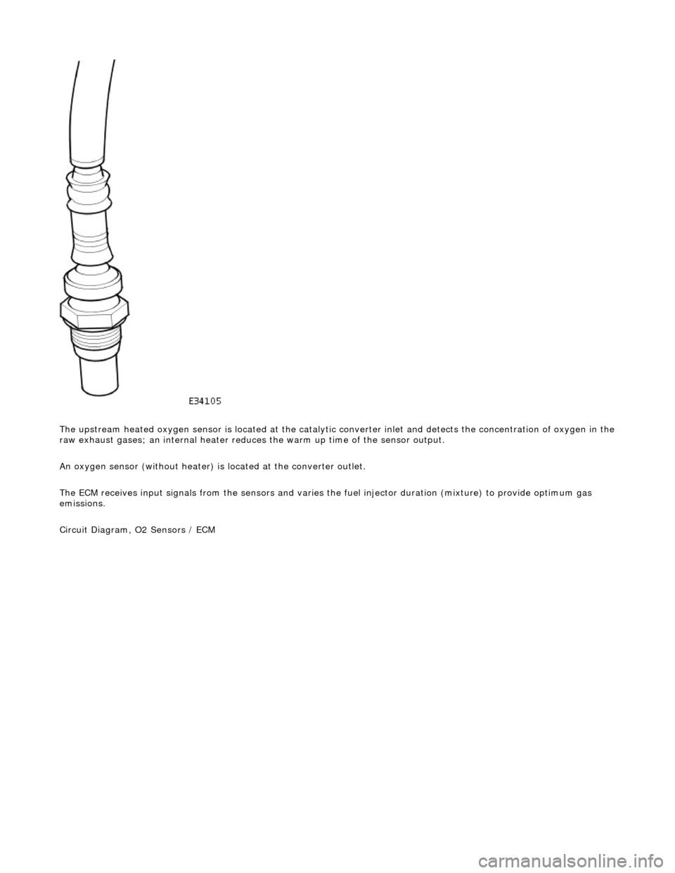
The upstream heated oxygen sensor is located at the catalytic converter inlet and detects the concentration of oxygen in the
raw exhaust gases; an internal heater reduces the warm up time of the sensor output.
An oxygen sensor (without heater) is located at the converter outlet.
The ECM receives input signals from the se nsors and varies the fuel injector duration (mixture) to provide optimum gas
emissions.
Circuit Diagram, O2 Sensors / ECM
Page 1695 of 2490
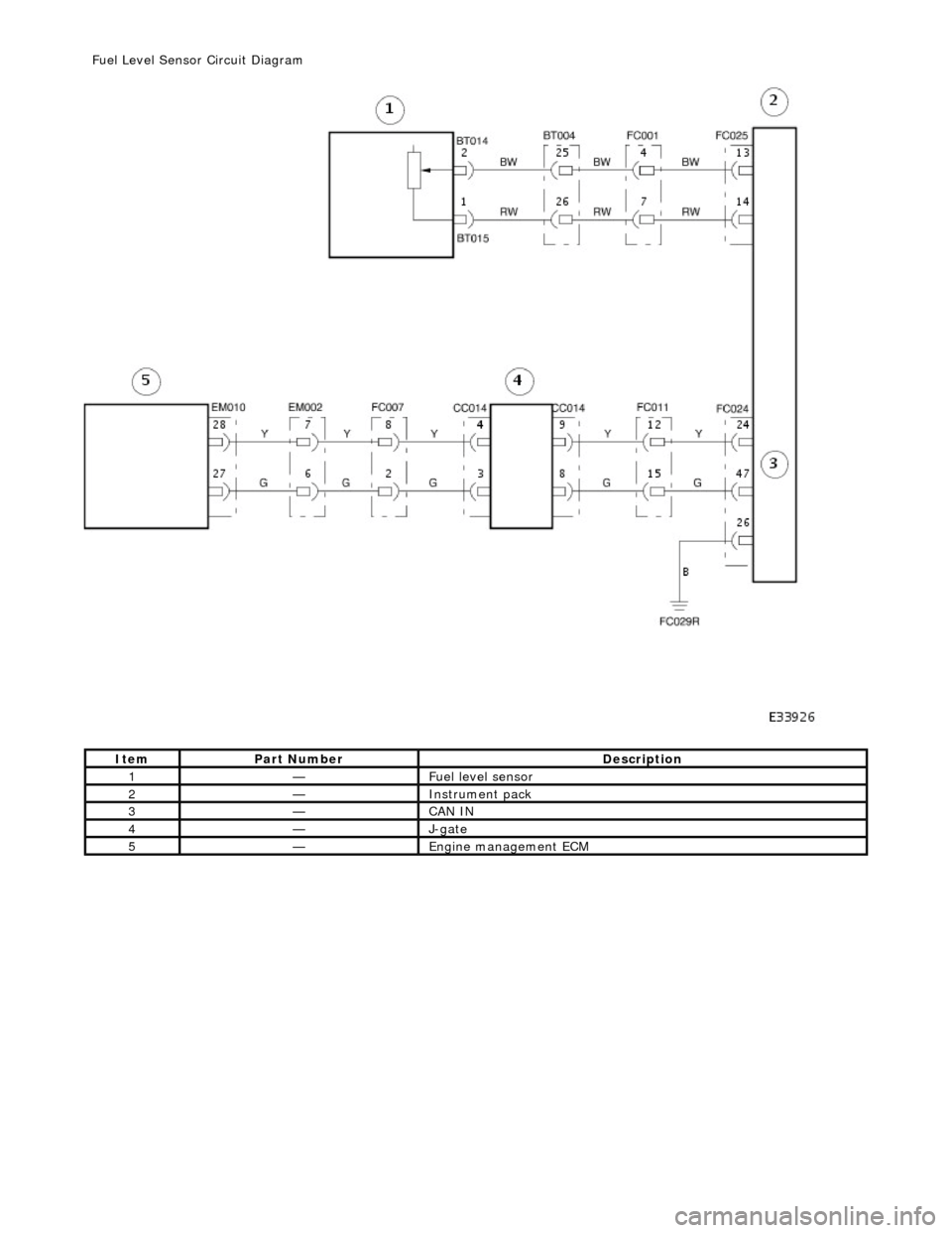
It
em
Par
t Number
De
scription
1—Fue
l level sensor
2—Instrument pack
3—CAN IN
4—J-
gate
5—Engine
management ECM
F
uel Level Sensor Circuit Diagram
Page 1696 of 2490
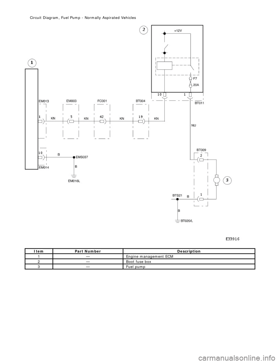
Ite
m
Par
t
Number
De
scr
iption
1—Engine
m
anagement ECM
2—Boot fuse box
3—Fue
l
pump
Ci
rcui
t Diagram, Fuel Pump -
Normally Aspirated Vehicles
Page 1697 of 2490
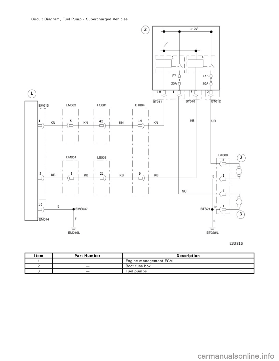
It
em
Par
t Number
De
scription
1—Engine
management ECM
2—Boot fuse box
3—Fue
l pumps
Ci
rcuit Diagram, Fuel Pump
- Supercharged Vehicles
Page 1745 of 2490
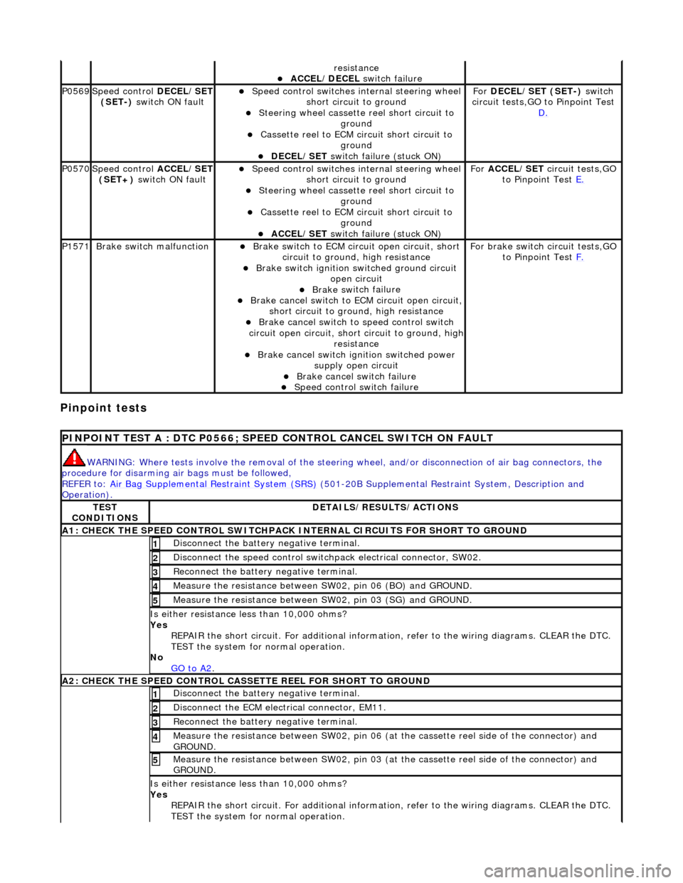
Pinpoint test
s
re
sistance
ACCEL/DECEL
swi
tch failure
P0569Speed
control
DECEL/SET
(SET-) switch ON fault
Speed
control switches internal steering wheel
short circuit to ground
S
teering wheel cassette
reel short circuit to
ground
Cassette reel
to ECM ci
rcuit short circuit to
ground
DEC
EL/SET
switch failure (stuck ON)
Fo
r
DECEL/SET (SET-) switch
circuit tests,GO to Pinpoint Test D.
P0570Speed
control
ACCEL/SET
(SET+) switch ON fault
Speed
control switches internal steering wheel
short circuit to ground
S
teering wheel cassette
reel short circuit to
ground
Cassette reel
to ECM ci
rcuit short circuit to
ground
ACC
EL/SET
switch failure (stuck ON)
Fo
r
ACCEL/SET circuit tests,GO
to Pinpoint Test E.
P1571Brake sw
itch malfunction
Brake sw
itch to ECM circuit open circuit, short
circuit to ground, high resistance
Brake sw
itch ignition switched ground circuit
open circuit
Brake sw
itch failure
Brake ca
ncel switch to
ECM circuit open circuit,
short circuit to ground, high resistance
Brake ca
ncel switch to speed control switch
circuit open circuit, shor t circuit to ground, high
resistance
Brake ca
ncel switch ignition switched power
supply open circuit
Brake ca
ncel switch failure
Spe
ed control switch failure
For brake swi
tch circuit tests,GO
to Pinpoint Test F.
P
INPOINT TEST A : DTC P0566; SPEED
CONTROL CANCEL SWITCH ON FAULT
WAR
NING: Where tests involve the removal of the steering
wheel, and/or disconnection of air bag connectors, the
procedure for disarming air bags must be followed,
REFER to: Air Bag Supplemental Re straint System (SRS)
(501-20B Supplemental Restra
int System, Description and
Operation).
TE
ST
CONDITIONS
D
ETAILS/RESULTS/ACTIONS
A1: CHECK
THE SPEED CONTROL SWITCHPACK IN
TERNAL CIRCUITS FOR SHORT TO GROUND
Di
sconnect the battery negative terminal.
1
Di
sconnect the speed control switch
pack electrical connector, SW02.
2
R
econnect the battery negative terminal.
3
Meas
ure the resistance between SW
02, pin 06 (BO) and GROUND.
4
Meas
ure the resistance between SW
02, pin 03 (SG) and GROUND.
5
Is either resi
stance
less than 10,000 ohms?
Yes REPAIR the short circuit. For addi tional information, refer to the wiring diagrams. CLEAR the DTC.
TEST the system for normal operation.
No GO to A2
.
A2: CHECK
THE SPEED CONTROL CASSE
TTE REEL FOR SHORT TO GROUND
Di
sconnect the battery negative terminal.
1
D
isconnect the ECM electrical connector, EM11.
2
R
econnect the battery negative terminal.
3
M
easure the resistance between SW02, pin 06 (at the cassette reel side of the connector) and
GROUND.
4
M
easure the resistance between SW02, pin 03 (at the cassette reel side of the connector) and
GROUND.
5
Is either resi
stance
less than 10,000 ohms?
Yes REPAIR the short circuit. For addi tional information, refer to the wiring diagrams. CLEAR the DTC.
TEST the system for normal operation.
Page 1746 of 2490

No
GO to A3.
A3: CHECK THE SPEED CONTRO L CANCEL SWITCH
ACTION
Meas
ure t
he resistance between SW02,
pin 06 (BO) and SW02, pin 03 (SG).
1
Operate
the speed control
CANCEL switch.
2
Do
es the resistance
vary by 680 ohms?
Yes Recheck DTCs. No short found. Po ssible intermittent fault. CLEAR the DTC. TEST the system for
normal operation.
No INSTALL a new speed control switchpack. CLEAR the DTC. TEST the system for normal operation.
PINPOINT TEST B : DTC
P0567; SPEED
CONTROL RESUME SWITCH ON FAULT
WARN
ING: Where tests involve the removal of the steering
wheel, and/or disconnection of air bag connectors, the
procedure for disarming air bags must be followed,
REFER to: Air Bag Supplemental Re straint System (SRS)
(50
1-20B Supplemental Restra
int System, Description and
Operation).
TE S
T
CONDITIONS
D E
TAILS/RESULTS/ACTIONS
B1: CHECK
THE SPEED CONTR
OL SWITCHPACK IN
TERNAL CIRCUITS FOR SHORT TO GROUND
Disc
onnect the speed control switch
pack electrical connector, SW02.
1
Measure t
he resistance between SW
02, pin 06 (BO) and GROUND.
2
Measure t
he resistance between SW
02, pin 03 (SG) and GROUND.
3
Is either resistance le
ss than 10,000 ohms?
Yes REPAIR the short circuit. For addi tional information, refer to the wiring diagrams. CLEAR the DTC.
TEST the system for normal operation.
No GO to B2
.
B2: CHECK THE SPEED CONTR
OL CASSETTE REEL FOR SHORT TO GROUND
M
e
asure the resistance between SW02, pin 06 (at the cassette reel side of the connector) and
GROUND.
1
Me
asure the resistance between SW02, pin 03 (at the cassette reel side of the connector) and
GROUND.
2
Is either resistance le
ss than 10,000 ohms?
Yes REPAIR the short circuit. For addi tional information, refer to the wiring diagrams. CLEAR the DTC.
TEST the system for normal operation.
No GO to B3
.
B3: CHECK THE SPEED CONTR
OL RESUME SWITCH ACTION
Meas
ure t
he resistance between SW02,
pin 06 (BO) and SW02, pin 03 (SG).
1
Operate
the speed control
RESUME switch.
2
Do
es the resistance
vary by 430 ohms?
Yes Recheck DTCs. No short found. Po ssible intermittent fault. CLEAR the DTC. TEST the system for
normal operation.
No INSTALL a new speed control switchpack. CLEAR the DTC. TEST the system for normal operation.
PINPOINT TES
T C : DTC P0568; SPEED CONTROL SWITCH GROUND MALFUNCTION
WAR
N
ING: Where tests involve the removal of the steering
wheel, and/or disconnection of air bag connectors, the
procedure for disarming air bags must be followed,
REFER to: Air Bag Supplemental Re straint System (SRS)
(50
1-20B Supplemental Restra
int System, Description and
Operation).
TE S
T
CONDITIONS
D E
TAILS/RESULTS/ACTIONS
C1: CHECK FOR CONTINUITY T
H
ROUGH STEERING WHEEL
CANCEL AND RESUME SWITCHES (SWITCHES OPEN)
Disc
onnect the speed control switch
pack electrical connector, SW02.
1
Check for c
ontinuity between SW02
, pins 06 (BO) and 03 (SG) wi th the steering wheel switches
inactive.
2
Page 1748 of 2490

Is the res
istance greater than 5 ohms?
Yes REPAIR the circuit. For additional information, refer to the wiring diagrams. CLEAR the DTC. TEST
the system for normal operation.
No GO to C10
.
C10: CHECK T H
E ECM TO CASSETTE REEL
CIRCUIT FOR CONTINUITY (CIRCUIT 2)
Measure t
he resistance between EM11,
pin 05 (SG) and SW01, pin 03 (SG).
1
Is the res
istance greater than 5 ohms?
Yes REPAIR the circuit. For additional information, refer to the wiring diagrams. CLEAR the DTC. TEST
the system for normal operation.
No Contact dealer technical support for advice on possible ECM failure.
PI
NPOINT TEST D : DTC P0
569; SPEED CONTROL DECEL/SET- SWITCH ON FAULT
WARN
ING: Where tests involve the removal of the steering
wheel, and/or disconnection of air bag connectors, the
procedure for disarming air bags must be followed,
REFER to: Air Bag Supplemental Re straint System (SRS)
(50
1-20B Supplemental Restra
int System, Description and
Operation).
TE S
T
CONDITIONS
D E
TAILS/RESULTS/ACTIONS
D1: CHECK
THE SPEED CONTROL SWITCHPACK IN
TERNAL CIRCUITS FOR SHORT TO GROUND
Disc
onnect the speed control switch
pack electrical connector, SW02.
1
Measure t
he resistance between SW
02, pin 06 (BO) and GROUND.
2
Measure t
he resistance between SW
02, pin 04 (SR) and GROUND.
3
Is either resistance le
ss than 10,000 ohms?
Yes REPAIR the short circuit. For addi tional information, refer to the wiring diagrams. CLEAR the DTC.
TEST the system for normal operation.
No GO to D2
.
D2: CHECK
THE SPEED CONTROL CASSE
TTE REEL FOR SHORT TO GROUND
Me
asure the resistance between SW02, pin 06 (at the cassette reel side of the connector) and
GROUND.
1
M e
asure the resistance between SW02, pin 04 (at the cassette reel side of the connector) and
GROUND.
2
Is either resi stance le
ss than 10,000 ohms?
Yes REPAIR the short circuit. For addi tional information, refer to the wiring diagrams. CLEAR the DTC.
TEST the system for normal operation.
No GO to D3
.
D3: CHECK
THE SPEED CONTROL DECEL/SET- SWITCH ACTION
Meas
ure t
he resistance between SW02,
pin 06 (BO) and SW02, pin 04 (SR).
1
Operate
the speed control
DECEL/SET- switch.
2
Do
es the resistance
vary by 680 ohms?
Yes Recheck DTCs. No short found. Po ssible intermittent fault. CLEAR the DTC. TEST the system for
normal operation.
No INSTALL a new speed control switchpack. CLEAR the DTC. TEST the system for normal operation.
PINPOI
NT TEST E : DTC P0570; SPEED CONTROL "ACCEL/SET+" SWITCH "ON" FAULT
WAR
N
ING: Where tests involve the removal of the steering
wheel, and/or disconnection of air bag connectors, the
procedure for disarming air bags must be followed,
REFER to: Air Bag Supplemental Re straint System (SRS)
(50
1-20B Supplemental Restra
int System, Description and
Operation).
TE S
T
CONDITIONS
D E
TAILS/RESULTS/ACTIONS
E1
: CHECK THE SPEED CONTROL
SWITCHPACK IN
TERNAL CIRCUITS FOR SHORT TO GROUND
Page 1749 of 2490
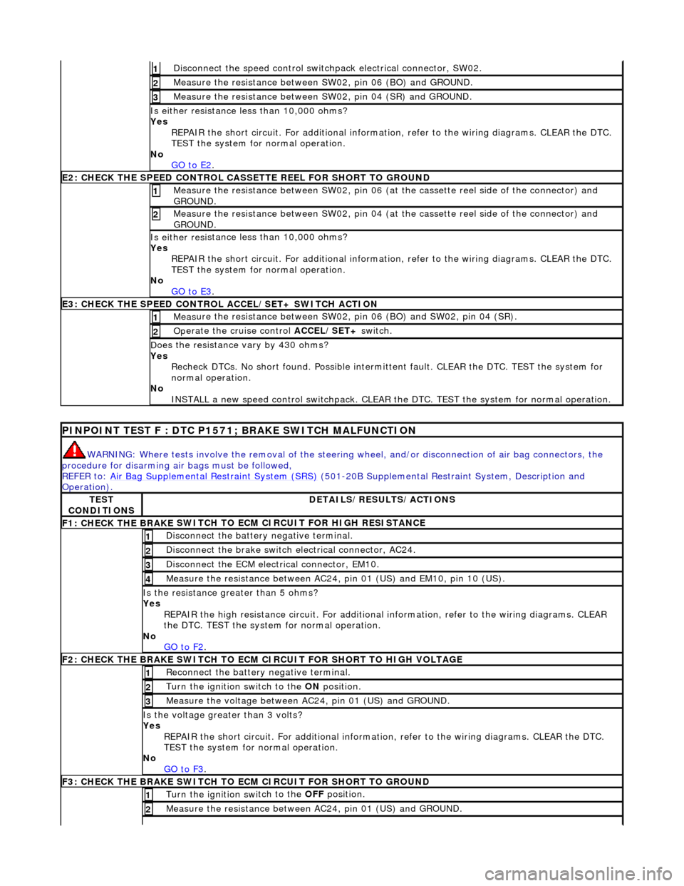
Di
sconnect the speed control switch
pack electrical connector, SW02.
1
Meas
ure the resistance between SW
02, pin 06 (BO) and GROUND.
2
Meas
ure the resistance between SW
02, pin 04 (SR) and GROUND.
3
Is either resi
stance
less than 10,000 ohms?
Yes REPAIR the short circuit. For addi tional information, refer to the wiring diagrams. CLEAR the DTC.
TEST the system for normal operation.
No GO to E2
.
E2
: CHECK THE SPEED CONTROL CASSE
TTE REEL FOR SHORT TO GROUND
M
easure the resistance between SW02, pin 06 (at the cassette reel side of the connector) and
GROUND.
1
M
easure the resistance between SW02, pin 04 (at the cassette reel side of the connector) and
GROUND.
2
Is either resi
stance
less than 10,000 ohms?
Yes REPAIR the short circuit. For addi tional information, refer to the wiring diagrams. CLEAR the DTC.
TEST the system for normal operation.
No GO to E3
.
E3
: CHECK THE SPEED CONTROL
ACCEL/SET+ SWITCH ACTION
Meas
ure the resistance between SW02,
pin 06 (BO) and SW02, pin 04 (SR).
1
Op
erate the cruise control
ACCEL/SET+ switch.
2
D
oes the resistance
vary by 430 ohms?
Yes Recheck DTCs. No short found. Po ssible intermittent fault. CLEAR the DTC. TEST the system for
normal operation.
No INSTALL a new speed control switchpack. CLEAR the DTC. TEST the system for normal operation.
P
INPOINT TEST F : DTC P1571;
BRAKE SWITCH MALFUNCTION
WAR
NING: Where tests involve the removal of the steering
wheel, and/or disconnection of air bag connectors, the
procedure for disarming air bags must be followed,
REFER to: Air Bag Supplemental Re straint System (SRS)
(501-20B Supplemental Restra
int System, Description and
Operation).
TE
ST
CONDITIONS
D
ETAILS/RESULTS/ACTIONS
F1: CHECK THE BRAKE
SWITCH TO
ECM CIRCUIT FOR HIGH RESISTANCE
Di
sconnect the battery negative terminal.
1
Di
sconnect the brake switch electrical connector, AC24.
2
D
isconnect the ECM electrical connector, EM10.
3
Meas
ure the resistance between AC24,
pin 01 (US) and EM10, pin 10 (US).
4
Is th
e resistance greater than 5 ohms?
Yes REPAIR the high resistance circui t. For additional information, refer to the wiring diagrams. CLEAR
the DTC. TEST the system for normal operation.
No GO to F2
.
F2: CHECK THE BRAKE
SWITCH TO ECM
CIRCUIT FOR SHORT TO HIGH VOLTAGE
R
econnect the battery negative terminal.
1
Turn the ignition swi
tch to the ON
position.
2
M
easure the voltage between AC24, pin 01 (US) and GROUND.
3
Is th
e voltage greater than 3 volts?
Yes REPAIR the short circuit. For addi tional information, refer to the wiring diagrams. CLEAR the DTC.
TEST the system for normal operation.
No GO to F3
.
F3: CHECK THE BRAKE
SWITCH TO
ECM CIRCUIT FOR SHORT TO GROUND
Turn the ignition swi
tch to the OFF
position.
1
Meas
ure the resistance between AC24, pin 01 (US) and GROUND.
2
Page 1750 of 2490
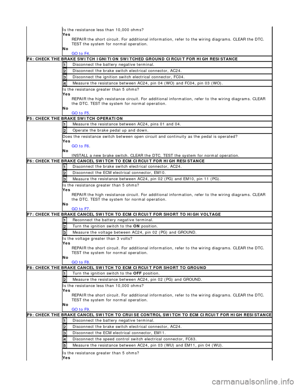
Is t
he resistance less than 10,000 ohms?
Yes REPAIR the short circuit. For addi tional information, refer to the wiring diagrams. CLEAR the DTC.
TEST the system for normal operation.
No GO to F4
.
F4: CHECK THE BRAKE SWITCH IGNITION SWIT
C
HED GROUND CIRCUIT FOR HIGH RESISTANCE
Di
sc
onnect the battery negative terminal.
1
Di
sc
onnect the brake switch electrical connector, AC24.
2
Di
sc
onnect the ignition switch electrical connector, FC04.
3
Measure t
he resistance between AC24,
pin 04 (WO) and FC04, pin 03 (WO).
4
Is the res
istance greater than 5 ohms?
Yes REPAIR the high resistance circui t. For additional information, refer to the wiring diagrams. CLEAR
the DTC. TEST the system for normal operation.
No GO to F5
.
F5: CHECK THE BRAKE SWITCH O
PERATION
Me
asure
the resistance between AC24, pins 01 and 04.
1
O
p
erate the brake pedal up and down.
2
Doe
s
the resistance switch between open circuit and continuity as the pedal is operated?
Yes GO to F6
.
No
INST
ALL a new brake switch. CLEAR the DTC.
TEST the system for normal operation.
F6: CHECK THE BRAKE CANCEL
SWITCH
TO ECM CIRCUIT FOR HIGH RESISTANCE
Disc
onnect the brake switch electrical connector, AC24.
1
D
i
sconnect the ECM electrical connector, EM10.
2
Me
asure
the resistance between AC24, pin 02 (PG) and EM10, pin 11 (PG).
3
Is th
e res
istance greater than 5 ohms?
Yes REPAIR the high resistance circui t. For additional information, refer to the wiring diagrams. CLEAR
the DTC. TEST the system for normal operation.
No GO to F7
.
F7: CHECK THE BRAKE CANCEL
SWITCH TO
ECM CIRCUIT FOR SHORT TO HIGH VOLTAGE
Re
connect the battery negative terminal.
1
Turn the ignition swi
t
ch to the ON
position.
2
Me
asure the voltage between AC24, pin 02 (PG) and GROUND.
3
Is th
e volt
age greater than 3 volts?
Yes REPAIR the short circuit. For addi tional information, refer to the wiring diagrams. CLEAR the DTC.
TEST the system for normal operation.
No GO to F8
.
F8: CHECK THE BRAKE CANCEL
SWITCH
TO ECM CIRCUIT FO R SHORT TO GROUND
Turn the ignition swit
ch to the OFF
position.
1
Measure t
he resistance between AC24, pin 02 (PG) and GROUND.
2
Is
t
he resistance less than 10,000 ohms?
Yes REPAIR the short circuit. For addi tional information, refer to the wiring diagrams. CLEAR the DTC.
TEST the system for normal operation.
No GO to F9
.
F9: CHECK THE BRAKE CANCEL
SWITCH
TO CRUISE CONTROL SWITCH TO ECM CIRCUIT FOR HIGH RESISTANCE
Disc
onnect the battery negative terminal.
1
Di
sc
onnect the brake switch electrical connector, AC24.
2
D
i
sconnect the ECM electrical connector, EM11.
3
Di
sc
onnect the speed control switch electrical connector, FC63.
4
Me
asure
the resistance between AC24, pin 03 (WU) and EM11, pin 04 (WU).
5
Is th
e res
istance greater than 5 ohms?
Yes
Page 1751 of 2490

R
EPAIR the high resistance circui
t. For additional information, refer to the wiring diagrams. CLEAR
the DTC. TEST the system for normal operation.
No GO to F10
.
F10: CHECK
THE BRAKE CANCEL SWITCH TO CRUISE CO
NTROL SWITCH TO ECM CIRCUIT FOR SHORT TO HIGH
VOLTAGE
R
econnect the battery negative terminal.
1
Turn the ignition swi
tch to the ON
position.
2
M
easure the voltage between AC24, pin 03 (WU) and GROUND.
3
Is th
e voltage greater than 3 volts?
Yes REPAIR the short circuit. For addi tional information, refer to the wiring diagrams. CLEAR the DTC.
TEST the system for normal operation.
No GO to F11
.
F11: CHECK
THE BRAKE CANCEL SWITCH TO CRUISE
CONTROL SWITCH TO ECM CIRCUIT FOR SHORT TO
GROUND
Turn the ignition swi
tch to the
OFF position.
1
Meas
ure the resistance between AC24, pin 03 (WU) and GROUND.
2
Is
the resistance less than 10,000 ohms?
Yes REPAIR the short circuit. For addi tional information, refer to the wiring diagrams. CLEAR the DTC.
TEST the system for normal operation.
No GO to F12
.
F12: CHECK
THE BRAKE CANCEL SWITCH
IGNITION SWITCHED POWER SUPPLY
Turn the ignition swi
tch to the ON
position.
1
M
easure the voltage between AC24, pin 03 (WU) and GROUND.
2
Is th
e voltage less than 10 volts?
Yes REPAIR the circuit between the brake cancel sw itch and the ignition switch. For additional
information, refer to the wiring diagrams. CLEAR the DTC. TEST the system for normal operation.
No GO to F13
.
F13: CHECK
THE BRAKE CA
NCEL SWITCH OPERATION
Me
asure the resistance between AC24, pins 02 and 03.
1
O
perate the brake pedal up and down.
2
Doe
s the resistance switch between open circuit and continuity as the pedal is operated?
Yes Recheck the DTCs. Failure of other cruise contro l circuits will set other DTCs, indicating the
component at fault.
No INSTALL a new brake cancel switch. CLEAR the DT C. TEST the system for normal operation.