heater JAGUAR X308 1998 2.G Owner's Manual
[x] Cancel search | Manufacturer: JAGUAR, Model Year: 1998, Model line: X308, Model: JAGUAR X308 1998 2.GPages: 2490, PDF Size: 69.81 MB
Page 1197 of 2490

пЃ¬Exhaus
t leak
пЃ¬Low e
xhaust temperature
пЃ¬Cat
alyst monitor sensor failure
P0151Le
ft-hand H02S sense circuit low
voltage
пЃ¬H02
S disconnected
пЃ¬H0
2S to ECM wiring open circuit
пЃ¬H0
2S short circuit to ground
пЃ¬H0
2S failure
F
or left-hand HO2S circuit tests, GO
to Pinpoint Test H.
.
P0152Le
ft-hand H02S sense circuit high
voltage
пЃ¬H02
S sensing circuit short circuit to
high voltage
пЃ¬H0
2S ground braided shield open
circuit
пЃ¬H0
2S failure
F
or left-hand HO2S circuit tests,GO to
Pinpoint Test H.
.
P0153Le
ft-hand H02S sense circuit slow
response
пЃ¬Engine
misfire
пЃ¬H02
S disconnected
пЃ¬H0
2S mechanical damage
пЃ¬H0
2S to ECM wiring intermittent
open circuit
пЃ¬H02
S sensing circuit short circuit to
high voltage
пЃ¬H0
2S short circuit to ground
пЃ¬H0
2S ground braided shield open
circuit
пЃ¬H0
2S heater circuit fault
пЃ¬Exhaus
t leak
пЃ¬Low e
xhaust temperature
пЃ¬Injector fl
ow partially blocked
пЃ¬Catal
yst efficiency decrease
пЃ¬H0
2S failure
Chec
k for 'engine misfire detected'
DTCs. For HO2S circ uit tests, GO to
Pinpoint Test H.
. Check for exhaust
leak
s,
REFER to Section 309
-00
Exhaust
Sy
stem
.
Chec
k injectors,
REFER to Section 303
-04
Fuel
Charging and Con
trols
.
P0155Left-hand H02S heater
circuit
malfunction
пЃ¬H02
S disconnected
пЃ¬H0
2S heater power supply open
circuit
пЃ¬H0
2S heater to ECM wiring short
circuit or open circuit
пЃ¬H0
2S heater failure
F
or left-hand HO2S heater circuit
tests,GO to Pinpoint Test I.
.
P0157Le
ft-hand catalyst monitor sensor
sense circuit low voltage
пЃ¬Catal
yst monitor sensor
disconnected
пЃ¬Catal
yst monitor sensor to ECM
wiring open circuit
пЃ¬Catal
yst monitor sensor short
circuit to ground
пЃ¬Cat
alyst monitor sensor failure
F
or left-hand catalyst monitor sensor
circuit tests,GO to Pinpoint Test J.
.
P0158Le
ft-hand catalyst monitor sensor
sense circuit high voltage
пЃ¬Catal
yst monitor sensor sensing
circuit short circuit to high voltage
пЃ¬Catalyst
monitor sensor ground
braided shield open circuit
пЃ¬Cat
alyst monitor sensor failure
F
or left-hand catalyst monitor sensor
circuit tests,GO to Pinpoint Test J.
.
P0160Le
ft-hand catalyst monitor sensor
sense circuit no activity
пЃ¬Catal
yst monitor sensor
disconnected
пЃ¬Catal
yst monitor sensor
mechanical damage
пЃ¬Catal
yst monitor sensor to ECM
wiring open circuit
пЃ¬Catal
yst monitor sensor sensing
circuit short circuit to high voltage
пЃ¬Catal
yst monitor sensor short
circuit to ground
пЃ¬Catalyst
monitor sensor ground
braided shield open circuit
пЃ¬Exhaus
t leak
пЃ¬Low e
xhaust temperature
пЃ¬Cat
alyst monitor sensor failure
F
or left-hand catalyst monitor sensor
circuit tests,GO to Pinpoint Test J.
.
Check f
or exhaust leaks,
REFER to Section 309
-00
Exhaust
Sy
stem
.
P0171Right
-hand cylinders combustion
too lean
пЃ¬Air
intake leak between MAF senso
r and th
rottle
пЃ¬F
uel filter system blockage
пЃ¬F
uel injector blockage
пЃ¬F
uel pressure regulator failure (low
fuel pressure)
пЃ¬Low f
uel pump output
Check ai
r intake system for leaks,
REFER to Section 303
-1
2 Intake Air
Distribu
tion and Filtering
.
Check the fuel fi
lter,
REFER to Section 310
-01
Fuel Tank
and Lines.
Chec
k the fuel injectors and fuel
Page 1200 of 2490
пЃ¬KS fail
ure
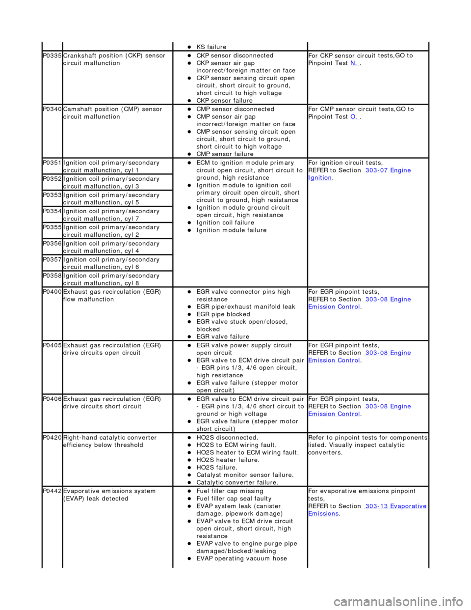
P0335Cranksh
a
ft positi
on (CKP) sensor
circuit malfunction
пЃ¬CK P
sensor disconnected
пЃ¬CKP sensor air gap
i
n
correct/foreign matter on face
пЃ¬CKP sensor sen
s
ing circuit open
circuit, short circuit to ground,
short circuit to high voltage
пЃ¬CKP s e
nsor failure
F
or CKP sensor circ ui
t tests,GO to
Pinpoint Test N.
.
P0340Camshaft position
(CMP) sensor
circuit malfunction
пЃ¬CM P
sensor disconnected
пЃ¬CMP sensor air gap
i
n
correct/foreign matter on face
пЃ¬CMP sensor sen
s
ing circuit open
circuit, short circuit to ground,
short circuit to high voltage
пЃ¬CMP s e
nsor failure
F
or CMP sensor circ ui
t tests,GO to
Pinpoint Test O.
.
P0351Igniti
on coil primary/secondary
circuit malfunction, cyl 1
пЃ¬ECM to ignit
ion module primary
circuit open circuit, short circuit to
ground, high resistance
пЃ¬Igniti
on module to ignition coil
primary circuit open circuit, short
circuit to ground, high resistance
пЃ¬Ignition modu le
ground circuit
open circuit, hi gh resistance
пЃ¬Ignition coil fail
ure
пЃ¬Ignition modul
e
failure
F
o
r ignition circuit tests,
REFER to Section 303
-07 En
gine
Ignition. P0352Ignit
i
on coil primary/secondary
circuit malfunction, cyl 3
P0353Ignit i
on coil primary/secondary
circuit malfunction, cyl 5
P0354Ignit i
on coil primary/secondary
circuit malfunction, cyl 7
P0355Ignit i
on coil primary/secondary
circuit malfunction, cyl 2
P0356Ignit i
on coil primary/secondary
circuit malfunction, cyl 4
P0357Ignit i
on coil primary/secondary
circuit malfunction, cyl 6
P0358Ignit i
on coil primary/secondary
circuit malfunction, cyl 8
P0400Exhaus t gas
recirculation (EGR)
flow malfunction
пЃ¬EGR valve c
onnector pins high
resistance
пЃ¬EGR pipe/exhaust manifol
d leak
пЃ¬EGR pipe blocke
d
пЃ¬EGR valve st
uck open/closed,
blocked
пЃ¬EGR valve fai
lure
For EGR
pinpoint t
ests,
REFER to Section 303
-08 En
gine
Emission Control.
P0405Exhaus
t gas
recirculation (EGR)
drive circuits open circuit
пЃ¬EGR valve power supply circuit
o p
en circuit
пЃ¬EGR valve t
o
ECM drive circuit pair
- EGR pins 1/3, 4/6 open circuit,
high resistance
пЃ¬EGR val v
e failure (stepper motor
open circuit)
For EGR pinpoint t
ests,
REFER to Section 303
-08 En
gine
Emissi
on Control.
P0406Exhaus t gas
recirculation (EGR)
drive circuits short circuit
пЃ¬EGR valve t o
ECM drive circuit pair
- EGR pins 1/3, 4/6 short circuit to
ground or high voltage
пЃ¬EGR val v
e failure (stepper motor
short circuit)
For EGR pinpoint t
ests,
REFER to Section 303
-08 En
gine
Emissi
on Control.
P0420Right-
hand catalytic converter
efficiency below threshold
пЃ¬HO2S di
sconnected.
пЃ¬HO2
S
to ECM wiring fault.
пЃ¬HO2
S
heater to ECM wiring fault.
пЃ¬HO2
S
heater failure.
пЃ¬HO2
S
failure.
пЃ¬Cat
a
lyst monitor sensor failure.
пЃ¬Catal
y
tic converter failure.
R
e
fer to pinpoint tests for components
listed. Visually inspect catalytic
converters.
P0442Evaporati v
e emissions system
(EVAP) leak detected
пЃ¬Fue l
filler cap missing
пЃ¬Fu
el filler cap seal faulty
пЃ¬EVAP system
leak (can
ister
damage, pipework damage)
пЃ¬EVAP v a
lve to ECM drive circuit
open circuit, short circuit, high
resistance
пЃ¬EVAP valve to engine pu rge pipe
damaged/blocked/leaking
пЃ¬EVAP ope r
ating vacuum hose
F
or evaporati
ve emissions pinpoint
tests,
REFER to Section 303
-1 3
Evaporative
Emissi
ons
.
Page 1211 of 2490
Is
the resistance less than 10,000 ohms?
Yes REPAIR the short circuit. For addi tional information, refer to the wiring diagrams. CLEAR the DTC.
TEST the system for normal operation.
No GO to E4
.
E4
: CHECK THE H02S GROUND
CIRCUIT FOR OPEN CIRCUIT
Re
connect the ECM electrical connector, EM12.
1
Meas
ure the resistance between EM21, pin 04 (BRD) and GROUND.
2
Is th
e resistance greater than 5 ohms?
Yes
REPAIR the circuit (this is a braide d lead which would require different repair techniques to standard
wiring). For additional information, refer to the wiring diagrams. CL EAR the DTC. TEST the system for
normal operation.
No INSTALL a new H02S.
REFER to Heated Oxygen Sensor (HO2S) RH
in this section.
CLEAR the DTC. TEST the syst em for normal operation.
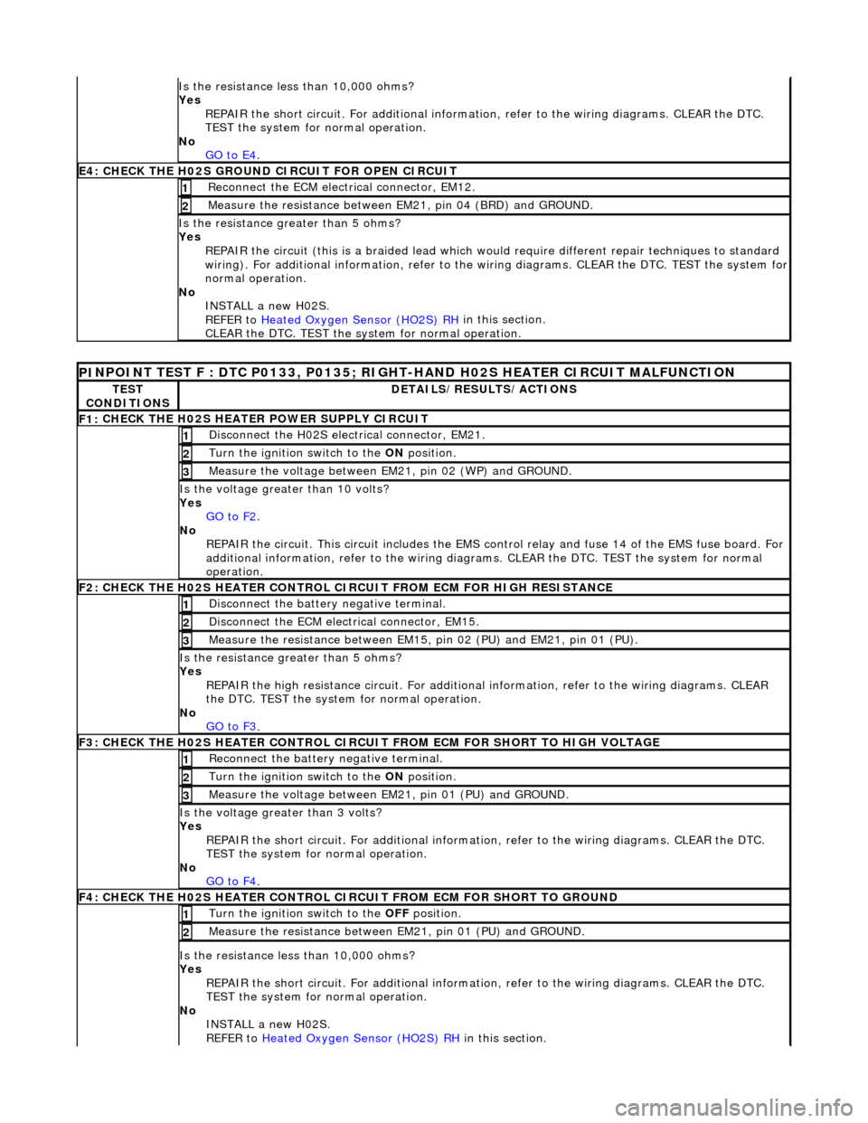
PI
NPOINT TEST F : DTC P0133, P0135; RIGHT-HAND H02S HEATER CIRCUIT MALFUNCTION
TE
ST
CONDITIONS
D
ETAILS/RESULTS/ACTIONS
F1:
CHECK THE H02S HEATER POWER SUPPLY CIRCUIT
D
isconnect the H02S electrical connector, EM21.
1
Turn the ignition swi
tch to the ON
position.
2
Meas
ure the voltage between EM21, pin 02 (WP) and GROUND.
3
Is the vol
tage greater than 10 volts?
Yes GO to F2
.
No
REPAIR the circuit. This circuit in cludes the EMS control relay and fu se 14 of the EMS fuse board. For
additional information, refer to the wiring diagrams. CLEAR the DT C. TEST the system for normal
operation.
F2: CHECK THE H02
S HEATER CONTROL CI
RCUIT FROM ECM FOR HIGH RESISTANCE
Di
sconnect the battery negative terminal.
1
D
isconnect the ECM electrical connector, EM15.
2
Me
asure the resistance between EM15, pin 02 (PU) and EM21, pin 01 (PU).
3
Is th
e resistance greater than 5 ohms?
Yes REPAIR the high resistance circui t. For additional information, refer to the wiring diagrams. CLEAR
the DTC. TEST the system for normal operation.
No GO to F3
.
F3: CHECK THE H02
S HEATER CONTROL CIRCUI
T FROM ECM FOR SHORT TO HIGH VOLTAGE
R
econnect the battery negative terminal.
1
Turn the ignition swi
tch to the ON
position.
2
Meas
ure the voltage between EM21, pin 01 (PU) and GROUND.
3
Is th
e voltage greater than 3 volts?
Yes REPAIR the short circuit. For addi tional information, refer to the wiring diagrams. CLEAR the DTC.
TEST the system for normal operation.
No GO to F4
.
F4: CHECK THE H02
S HEATER CONTROL CI
RCUIT FROM ECM FOR SHORT TO GROUND
Turn the ignition swi
tch to the OFF
position.
1
Meas
ure the resistance between EM21, pin 01 (PU) and GROUND.
2
Is
the resistance less than 10,000 ohms?
Yes REPAIR the short circuit. For addi tional information, refer to the wiring diagrams. CLEAR the DTC.
TEST the system for normal operation.
No INSTALL a new H02S.
REFER to Heated Oxygen Sensor (HO2S) RH
in this section.
Page 1213 of 2490
Yes
REPAIR the high resistance circui t. For additional information, refer to the wiring diagrams. CLEAR
the DTC. TEST the system for normal operation.
No GO to H2
.
H
2: CHECK THE H02S SENSE CIRCUIT FOR SHORT TO HIGH VOLTAGE
R
econnect the battery negative terminal.
1
Turn the ignition swi
tch to the ON
position.
2
M
easure the voltage between EM12, pin 14 (G) and GROUND.
3
Is th
e voltage greater than 3 volts?
Yes REPAIR the short circuit. For addi tional information, refer to the wiring diagrams. CLEAR the DTC.
TEST the system for normal operation.
No GO to H3
.
H
3: CHECK THE H02S SENSE CIRCUIT FOR SHORT TO GROUND
Turn the ignition swi
tch to the OFF
position.
1
Meas
ure the resistance between EM12, pin 14 (G) and GROUND.
2
Is
the resistance less than 10,000 ohms?
Yes REPAIR the short circuit. For addi tional information, refer to the wiring diagrams. CLEAR the DTC.
TEST the system for normal operation.
No GO to H4
.
H4:
CHECK THE H02S GROUND CIRCUIT FOR OPEN CIRCUIT
Re
connect the ECM electrical connector, EM12.
1
Meas
ure the resistance between EM23, pin 04 (BRD) and GROUND.
2
Is th
e resistance greater than 5 ohms?
Yes REPAIR the circuit (this is a braide d lead which would require different repair techniques to standard
wiring). For additional information, refer to the wiring diagrams. CL EAR the DTC. TEST the system for
normal operation.
No INSTALL a new H02S.
REFER to Heated Oxygen Sensor (HO2S) RH
in this section.
CLEAR the DTC. TEST the syst em for normal operation.
P
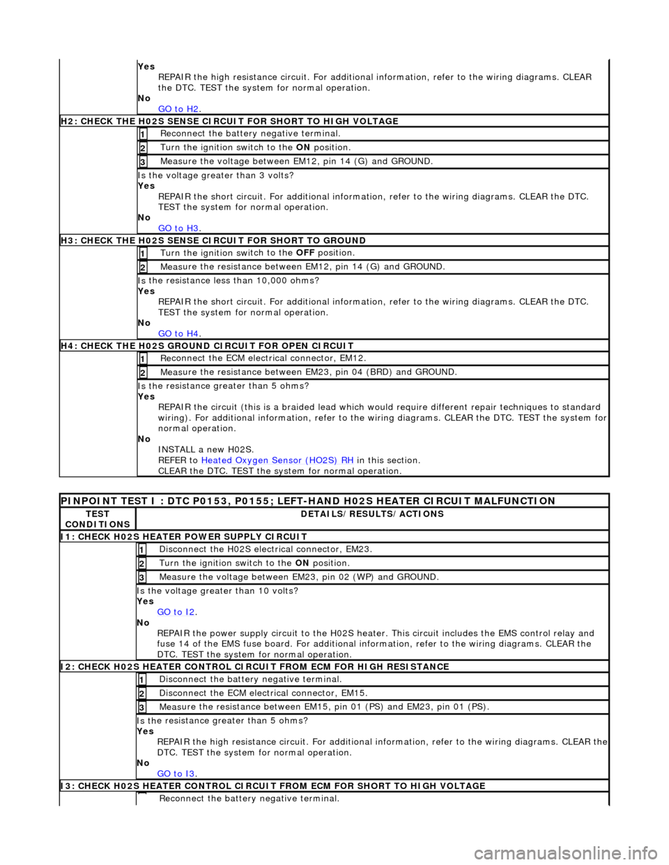
INPOINT TEST I : DTC P0153, P0155; LEFT-HAND H02S HEATER CIRCUIT MALFUNCTION
TE
ST
CONDITIONS
D
ETAILS/RESULTS/ACTIONS
I
1: CHECK H02S HEATER POWER SUPPLY CIRCUIT
D
isconnect the H02S electrical connector, EM23.
1
Turn the ignition swi
tch to the
ON position.
2
Meas
ure the voltage between EM23, pin 02 (WP) and GROUND.
3
Is the vol
tage greater than 10 volts?
Yes GO to I2
.
No
REPAIR the power supply circuit to the H02S heater. This circuit includes the EMS control relay and
fuse 14 of the EMS fuse board. For additional info rmation, refer to the wiring diagrams. CLEAR the
DTC. TEST the system for normal operation.
I
2: CHECK H02S HEATER CONTROL CIRC
UIT FROM ECM FOR HIGH RESISTANCE
Di
sconnect the battery negative terminal.
1
D
isconnect the ECM electrical connector, EM15.
2
Meas
ure the resistance between EM15,
pin 01 (PS) and EM23, pin 01 (PS).
3
Is th
e resistance greater than 5 ohms?
Yes REPAIR the high resistance circuit. For additional information, refer to the wiring diagrams. CLEAR the
DTC. TEST the system for normal operation.
No GO to I3
.
I
3: CHECK H02S HEATER CONTROL CIRCUIT
FROM ECM FOR SHORT TO HIGH VOLTAGE
R
econnect the battery negative terminal.
Page 1214 of 2490

1
Turn the ignition swit
ch to the
ON position.
2
Meas ure t
he voltage between EM23, pin 01 (PS) and GROUND.
3
Is th
e volt
age greater than 3 volts?
Yes REPAIR the short circuit. For addi tional information, refer to the wiring diagrams. CLEAR the DTC.
TEST the system for normal operation.
No GO to I4
.
I4
: CHECK H02S HEATER CONTROL CIRCUIT FROM ECM FOR SHORT TO GROUND
Turn the ignition swit
ch to the
OFF position.
1
Measure t
he resistance between EM23, pin 01 (PS) and GROUND.
2
Is t
he resistance less than 10,000 ohms?
Yes REPAIR the short circuit. For addi tional information, refer to the wiring diagrams. CLEAR the DTC.
TEST the system for normal operation.
No INSTALL a new H02S.
REFER to Heated Oxygen Sensor (HO2S) LH
in this
section.
CLEAR the DTC. TEST the system for normal operation.
P INPOINT TES
T J : DTC P0157, P0158; LEFT-H
AND CATALYST MONITOR SENSOR LOW/HIGH
VOLTAGE, NO ACTIVITY
TE S
T
CONDITIONS
D E
TAILS/RESULTS/ACTIONS
J
1
: CHECK THE CATALYST MONITOR SENSOR
SENSE CIRCUIT FOR HIGH RESISTANCE
Disc
onnect the battery negative terminal.
1
Di
sc
onnect the catalyst monitor sensor electrical connector, EM24.
2
Disc
onne
ct the ECM electrical connector, EM12.
3
Meas
ure t
he resistance between EM24, pin 02 (N) and EM12, pin 16 (N).
4
Is th
e res
istance greater than 5 ohms?
Yes REPAIR the high resistance circui t. For additional information, refer to the wiring diagrams. CLEAR
the DTC. TEST the system for normal operation.
No GO to J2
.
J2
: CHECK THE CATALYST MONITOR SENSOR SENSE CIRCUIT FOR SHORT TO HIGH VOLTAGE
R
e
connect the battery negative terminal.
1
Turn the ignition swi
t
ch to the ON
position.
2
Measure t
he voltage between EM12, pin 16 (N) and GROUND.
3
Is th
e volt
age greater than 3 volts?
Yes REPAIR the short circuit. For addi tional information, refer to the wiring diagrams. CLEAR the DTC.
TEST the system for normal operation.
No GO to J3
.
J3
: CHECK THE CATALYST MONITOR SENSOR
SENSE CIRCUIT FOR SHORT TO GROUND
Turn the ignition swit
ch to the OFF
position.
1
Measure t
he resistance between EM12, pin 16 (N) and GROUND.
2
Is t
he resistance less than 10,000 ohms?
Yes REPAIR the short circuit. For addi tional information, refer to the wiring diagrams. CLEAR the DTC.
TEST the system for normal operation.
No GO to J4
.
J4
: CHECK THE CATALYST MONITOR SENSOR
GROUND CIRCUIT FOR OPEN CIRCUIT
Reconn
ect the ECM electrical connector, EM12.
1
Meas
ure t
he resistance between EM24, pin 01 (BRD) and GROUND.
2
Is th
e res
istance greater than 5 ohms?
Yes REPAIR the circuit (this is a braide d lead which would require different repair techniques to standard
wiring). For additional information, refer to the wiring diagrams. CL EAR the DTC. TEST the system for
Page 1530 of 2490
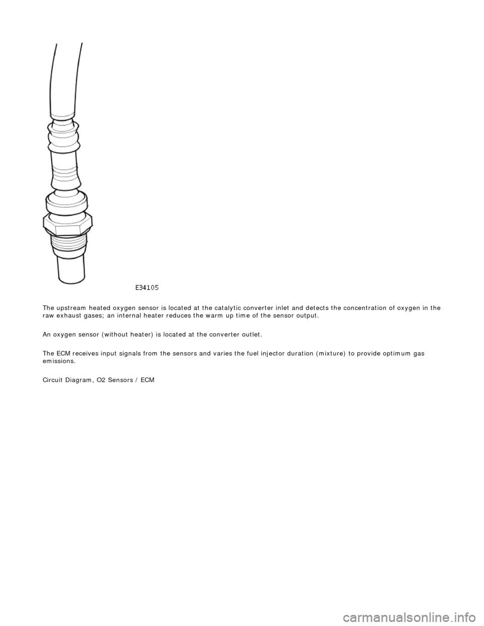
The upstream heated oxygen sensor is located at the catalytic converter inlet and detects the concentration of oxygen in the
raw exhaust gases; an internal heater reduces the warm up time of the sensor output.
An oxygen sensor (without heater) is located at the converter outlet.
The ECM receives input signals from the se nsors and varies the fuel injector duration (mixture) to provide optimum gas
emissions.
Circuit Diagram, O2 Sensors / ECM
Page 1531 of 2490
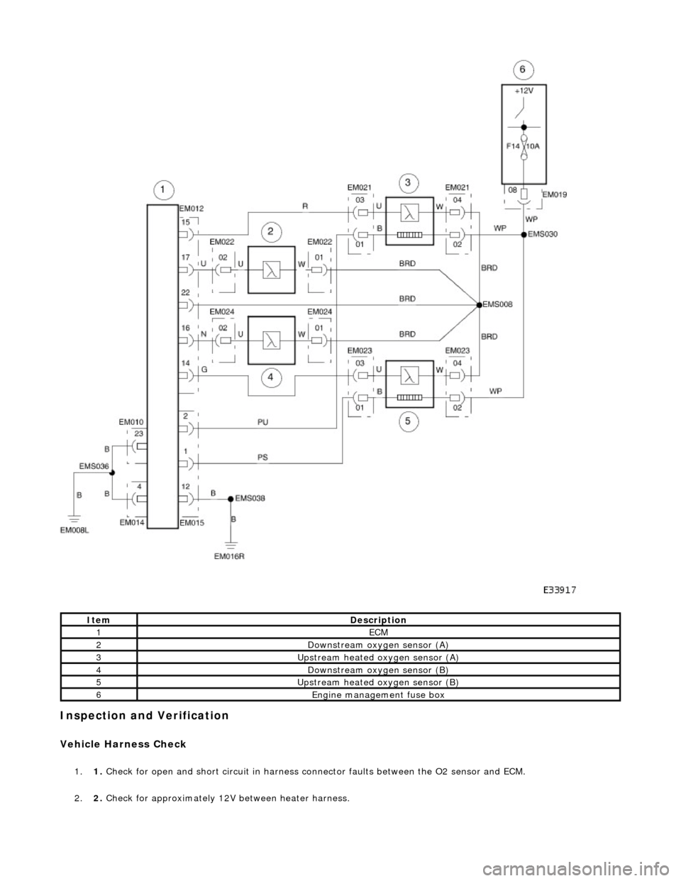
Inspection and Verification
Vehicle Harness Check
1.1. Check for open and short circuit in harness conn ector faults between the O2 sensor and ECM.
2. 2. Check for approximately 12V between heater harness.
ItemDescription
1ECM
2Downstream oxygen sensor (A)
3Upstream heated oxygen sensor (A)
4Downstream oxygen sensor (B)
5Upstream heated oxygen sensor (B)
6Engine management fuse box
Page 1532 of 2490

Heater Resistance Check
1.1. Verify that the resistance between the heater term inals is between 4OHM and 10OHM at -20В°C to 100В°C.
Performance Check
1.1. Run the engine at 2500 RPM for two minutes, to heat up the O2 sensor.
2. 2. Check the voltage of the sensor output: Alternates between less than 0.4V at feed back engine conditions and in
excess of 0.5V, see graph.
These voltages are for reference only.
3. 3. Check that cycle of the upstream se nsor output is in accordance with the appropriate pinpoint test.
4. 4. Check that cycle of the downstream sensor output is in accordance with the appropriate pinpoint test.
Page 1533 of 2490

Exhaust System - Exhaust System
Diagnosis and Testing
Symptom Chart
Symptom Chart
Special Tool(s)
Digital multimeter
Generic scantool
SymptomPossible SourcesAction
DTC P0420 Catalyst system efficiency below
threshold (Bank 1)Catalyst failure
Upstream O2 sensor failure
Downstream O2 sensor failure
O2 sensor heater failure
Associated harness / connector failure
*
*
*
*
*See DTC P0137, P0138
and P0140
*
DTC P0430 Catalyst system efficiency below
threshold (Bank 2)Catalyst failure
Upstream O2 sensor failure
Downstream O2 sensor failure
O2 sensor heater failure
Associated harness / connector failure
*
*
*
*
*See DTC P0157, P0158
and P0160
*
DTC P0131 O2 sensor circuit low voltage (Bank 1
sensor 1)O2 sensor failure
Sensor ground fault
Harness failure
Connector pin(s) bent, loose or corroded
*
*
*
*GO to Pinpoint Test A
*
DTC P0132 O2 sensor circuit high voltage (Bank
1 sensor 1)O2 sensor failure to B+
Sensor ground fault
Harness failure
Connector pin(s) bent or tracking
between connections. O2 sensor failure
*
*
*
*
*GO to Pinpoint Test A
*
DTC P0133 O2 sensor circuit slow response
(Bank 1 sensor 1)O2 sensor heater failure / out of spec
Sensor ground fault
Harness failure
Connector pin(s) bent or tracking
between connections. Low exhaust temperature
O2 sensor failure
*
*
*
*
*
*GO to Pinpoint Test B
*
DTC P0135 O2 sensor heater circuit malfunction
(Bank 1 sensor 1)O2 sensor failure
Harness failure
Connector pin(s) bent or tracking
between connections. ECM failure
*
*
*
*GO to Pinpoint Test A
*
DTC P0137 O2 sensor circuit low voltage (Bank 1
sensor 2)O2 sensor failure
Sensor ground fault
Harness failure
Connector pin(s) bent, loose or corroded
*
*
*
*GO to Pinpoint Test C
*
DTC P0138 O2 sensor circuit high voltage (Bank
1 sensor 2)O2 sensor failure to B+
Sensor ground fault
Harness failure
Connector pin(s) bent or tracking
*
*
*
*GO to Pinpoint Test C
*
Page 1534 of 2490

Pinpoint test A: P0131, P0132, P0135
between connections. ECM failure
*
DTC P0140 O2 sensor circuit no activity detected
(Bank 1 sensor 2)O2 sensor failure / out of spec
Sensor ground fault
Harness failure
Connector pin(s) bent or tracking
between connections. Low exhaust temperature
*
*
*
*
*GO to Pinpoint Test D
*
DTC P0420 Catalyst system efficiency below
threshold (bank 1)Downstream O2 sensor failure
Catalyst failure
Catalyst low temperature caused by
water splash
*
*
*GO to Pinpoint Test C
GO to Pinpoint Test D
*
*
DTC P0151 O2 sensor circuit low voltage (Bank 2
sensor 1)O2 sensor failure
Sensor ground fault
Harness failure
Connector pin(s) bent, loose or corroded
*
*
*
*GO to Pinpoint Test E
*
DTC P0152 O2 sensor circuit high voltage (Bank
2 sensor 1)O2 sensor failure to B+
Sensor ground fault
Harness failure
Connector pin(s) bent or tracking
between connections. O2 sensor failure
*
*
*
*
*GO to Pinpoint Test E
*
DTC P0153 O2 sensor circuit slow response
(Bank 2 sensor 1)O2 sensor heater failure / out of spec
Sensor ground fault
Harness failure
Connector pin(s) bent or tracking
between connections. Low exhaust temperature
O2 sensor failure
*
*
*
*
*
*GO to Pinpoint Test F
*
DTC P0155 O2 sensor heater circuit malfunction
(Bank 2 sensor 1)O2 sensor failure
Harness failure
Connector pin(s) bent or tracking
between connections. ECM failure
*
*
*
*GO to Pinpoint Test E
*
DTC P0157 O2 sensor circuit low voltage (Bank 2
sensor 2)O2 sensor failure
Sensor ground fault
Harness failure
Connector pin(s) bent, loose or corroded
*
*
*
*GO to Pinpoint Test G
*
DTC P0158 O2 sensor circuit high voltage (Bank
2 sensor 2)O2 sensor failure to B+
Sensor ground fault
Harness failure
Connector pin(s) bent or tracking
between connections. ECM failure
*
*
*
*
*GO to Pinpoint Test G
*
DTC P0160 O2 sensor circuit no activity detected
(Bank 2 sensor 2)O2 sensor failure / out of spec
Sensor ground fault
Harness failure
Connector pin(s) bent or tracking
between connections. Low exhaust temperature
*
*
*
*
*GO to Pinpoint Test H
*
DTC P0430 Catalyst system efficiency below
threshold (bank 2)Downstream O2 sensor failure
Catalyst failure
Catalyst low temperature caused by
water splash
*
*
*GO to Pinpoint Test G
GO to Pinpoint Test H
*
*
PINPOINT TEST A : P0131, P0132, P0135
TEST CONDITIONSDETAILS/RESULTS/ACTIONS
A1: RETRIEVE DTCS
• NOTE: Battery and or ECM disconnection prior to scanning wi
ll erase all data, ensure that the correct DTC is present.