rear axle JAGUAR X308 1998 2.G Owner's Manual
[x] Cancel search | Manufacturer: JAGUAR, Model Year: 1998, Model line: X308, Model: JAGUAR X308 1998 2.GPages: 2490, PDF Size: 69.81 MB
Page 238 of 2490

clip
.
5. With draw parkin
g brake cable th
rough equalizer (LH side cable
only).
6. Lower four-post lift.
7. Raise rear of vehicle to workin g height and support on stands.
Refer to section 100-02.
8. Remove rear wheel. Refer to section 204-04.
9. Posit i
on special tool (204-1
95) on hub studs and install
securing nuts.
10 . Slac
ken but do not remove hub to axle shaft securing nut.
11. Remove nuts and withdraw special tool (204-195) from hub.
12. Remove rear brake disc. Refer to 70.10.13.
13. Remove parking brake shoe s. Refer to 70.40.05.
14. Remove wheel speed sensor.
Page 249 of 2490

cli
p.
5. With
draw parking brake cable th
rough equalizer (LH side cable
only).
6. Lower four-post lift.
7. Raise rear of vehicle to workin g height and support on stands.
Refer to section 100-02.
8. Remove rear wheel. Refer to section 204-04.
9. Posit
ion special tool (204-1
95) on hub studs and install
securing nuts.
10
.
Slacken but do not remove hub to axle shaft securing nut.
11. Remove securing nuts from stud s and withdraw special tool
(204-195) from hub.
12. Remove rear brake disc. Refer to 70.10.13.
13. Remove parking brake shoe s. Refer to 70.40.05.
14. Remove wheel speed sensor.
Page 263 of 2490
O
ne locking wheel nut is fitted to each road wheel and can on
ly be removed by using the correctly coded socket. For road
wheels with exposed wheel nuts, each locking wheel nut is provided with a cover, which is removed using the cover removal
tool.
Locking wheel nuts have different coded keyway combinations with corresponding coded sockets. The correct socket, and
cover removal tool are supplied with the vehicle toolkit. Sets of sockets are available to Jaguar dealers.
Temporary Spare Wheel
•
NOTE: When using this type of spare wheel note that:
Speed
must not exceed 80 km/h (50 mph).
The normal ro
ad wheel must be reinstalled as soon as possible.
On
ly one temporary wheel may be installed to the vehicle.
Tracti
on control (where fitted
) must be switched OFF.
In certain markets, the spare wheel supplied with the vehicle is of the temporary-use type, it is narrower than the normal
road wheel and takes up less room in the luggage compartment.
Tire
s
The
radial ply tires shown in the 204-04
Specification Section are recommended by Jaguar to meet the high speed
performance of the vehicle. Only tires of identical specification may be fitted as replacements. Unde r no circumstances must
cross-ply tires be fitted.
Tire Inflation Pressures
Al
l recommended tires, including winter tire
s, must be inflated to the pressures shown in the 204-04 Specification Section.
Inflation pressures must only be checked when the tires are cold.
Tire Replac
ement and Wheel-Interchanging
W
hen renewal of tires is necessary, it is
preferable to fit a complete set. If two replacement tires are fitted (to one axle),
they must be of the same manufacturer and type as those on the other axle.
No attempt must be made to interchange wh eels from the front to the rear or vice-versa, as wear produc es a characteristic
pattern on each tire depending upon its po sition on the vehicle. If this position is changed after wear has occurred, the
performance of the tire w ill be adversely affected.
It should be remembered that new tires must be balanced befo re installing to the vehicle.
Win
ter Tires
•
NOTE: Speed must not exceed 210 km/h (131 mph) when winter tires are installed.
Jaguar recommended winter tires as specified in 204-04 Specification Section must only be fitted in complete four-wheel
sets of the same type and size.
Snow Chains and Spike Spider Traction System
Jagu
ar recommended snow chains, must on
ly be installed when using 16 inch wheels with 255/60 R16 winter tires.
• NOTE: When using snow chains or the spike spider traction system, note that:
Snow ch
ains and the spike spider
traction system must only be fitted to the rear wheels.
O
nly Jaguar recommended snow chains and spik
e spider traction system must be used.
The m
aximum permissible speed with winter tires and snow chains or the spike spider traction system fitted is 48
km/h (30 mph).
Tracti
on control (where fitted) must be
switched OFF when using snow chains or the spike spider traction system.
Page 273 of 2490
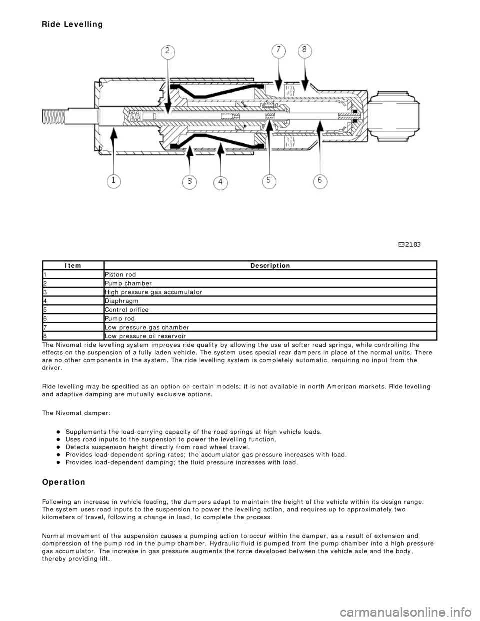
The
Nivomat ride levelling system improves ride quality by al
lowing the use of softer road springs, while controlling the
effects on the suspension of a fully laden vehicle. The system uses special rear dampers in place of the normal units. There
are no other components in th e system. The ride levelling system is comple tely automatic, requiring no input from the
driver.
Ride levelling may be specified as an opti on on certain models; it is not available in north American markets. Ride levelling
and adaptive damping are mu tually exclusive options.
The Nivomat damper:
Su
pplements the load-carrying capacity of th
e road springs at high vehicle loads.
Uses road inputs to the
suspension to power the levelling function.
De
tects suspension height dire
ctly from road wheel travel.
Provi
des load-dependent spring rates; the ac
cumulator gas pressure increases with load.
Pr
ovides load-dependent damping; the fluid pressure increases with load.
Op
eration
F
ollowing an increase in vehicle loading,
the dampers adapt to maintain the height of the vehicle within its design range.
The system uses road inputs to the suspension to power the levelling action, and requires up to approximately two
kilometers of travel, following a change in load, to complete the process.
Normal movement of the suspension caus es a pumping action to occur within the damper, as a result of extension and
compression of the pump rod in the pump chamber. Hydraulic fluid is pumped from the pump cham ber into a high pressure
gas accumulator. The increase in gas pressure augments the force developed between th e vehicle axle and the body,
thereby providing lift.
It
em
De
scription
1Pi
ston rod
2Pum
p chamber
3High
pressure
gas accumulator
4Diaphragm
5Co
ntrol orifice
6Pump rod
7Low pressure gas ch
amber
8Low pressure oil
reservoir
Ride Levelling
Page 284 of 2490
Re
ar Drive Axle/Differential -
Lubric
ants, Fluids, Sealants and Adhesives
Capacities
Torques
UnitSp
ecification
F
i
nal Drive
Shell Sp
irax Supe
r TS 90
Hub s
p
line to Axle shaft
Loct
it
e 270 Studlock or equivalent
UnitLi
t
ers
F
i
nal Drive
1,
90
Com p
onent
Nm
B
ol
t - Final drive nose plate
39
- 51
Bol t
- 'A' frame to final drive
9
0 -
110
Nu
t 'A' f
rame to rear mounting bracket
8
5 -
115
Nu
t -
Axle shaft to final drive flange
81
-
99
Nu
t -
Axle shaft to hub
3
04 -
336
N
u
t - Damper lower fixing
8
0 -
100
Bol
t
M12 - Jurid flexible coupling to
transmission and final drive flanges
75 -
88
N
u
t - Lower fulcrum
9
0 -
110
Nu
t -
Pendulum to final drive
1
60 -
200
N
u
t - Stabilizer to wishbone
30
-
40
N
u
t - Tie rod to final drive
8
5 -
105
Nu
t -
Tie rod to wide mounting bracket
8
5 -
115
Nu
t -
Wishbone pivot
8
0 -
100
N
u
t - Wishbone tie to final drive
8
5 -
105
N
u
t 'A' frame to wide mounting bracket
8
5 -
105
Page 285 of 2490
R
ear Drive Axle/Differential - Rear Drive Axle and Differential
Description an
d Operation
Loca
tion
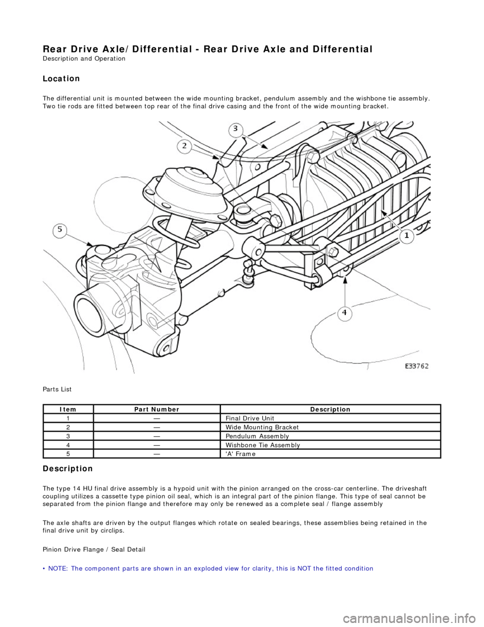
The differential
unit
is mounted between the wide mount ing bracket, pendulum assembly and the wishbone tie assembly.
Two tie rods are fitted between top rear of the final dr ive casing and the front of the wide mounting bracket.
Parts List
Description
The
type 14 HU final drive assembly is a hypoid unit with th
e pinion arranged on the cross-car centerline. The driveshaft
coupling utilizes a cassette type pinion oil seal, which is an in tegral part of the pinion flange. This type of seal cannot be
separated from the pinion fl ange and therefore may only be renewed as a complete seal / flange assembly
The axle shafts are driven by the output flanges which rotate on sealed bearings , these assemblies being retained in the
final drive unit by circlips.
Pinion Drive Flange / Seal Detail
• NOTE: The component parts are shown in an exploded view for clarity, this is NOT the fitted condition
It
em
Par
t Number
De
scription
1—F
inal Drive Unit
2—W
ide Mounting Bracket
3—Pen
dulum Assembly
4—Wi
shbone Tie Assembly
5—'A'
Frame
Page 288 of 2490
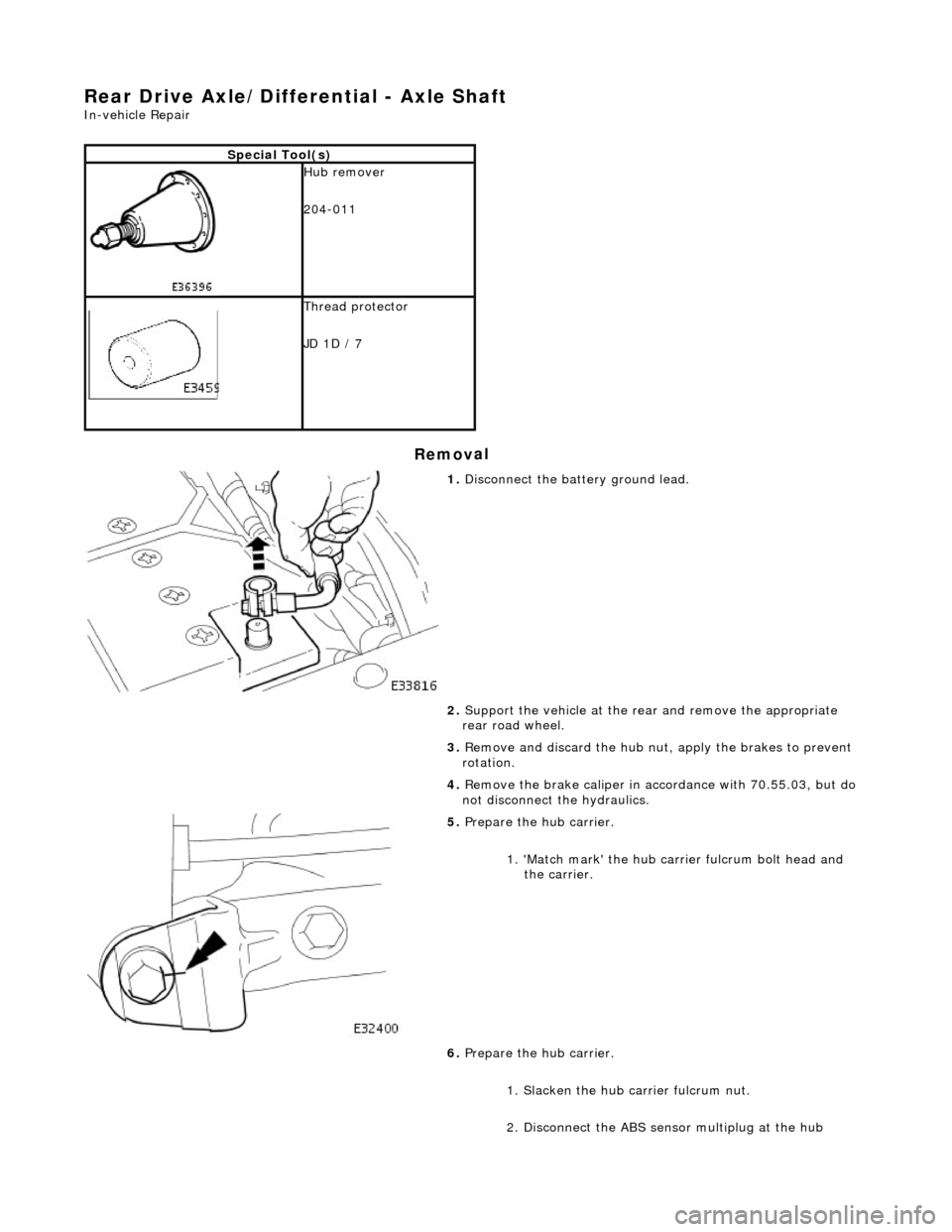
Re
ar Drive Axle/Differential - Axle Shaft
In-v
ehic
le Repair
Remov
a
l
S
p
ecial Tool(s)
Hub remover
2
04-011
Thread protector
JD
1D
/ 7
1. Disc
onnect the battery ground lead.
2. Support the vehicle at the rear and remove the appropriate
rear road wheel.
3. Remove and discard the hub nut, apply the brakes to prevent
rotation.
4. Remove the brake caliper in acco rdance with 70.55.03, but do
not disconnect the hydraulics.
5. Pr
epare the hub carrier.
1. 'Match mark' the hub carr ier fulcrum bolt head and
the carrier.
6. Prepare the hub carrier.
1. Slacken the hub ca rrier fulcrum nut.
2. Disconnect the ABS sensor multiplug at the hub
Page 290 of 2490
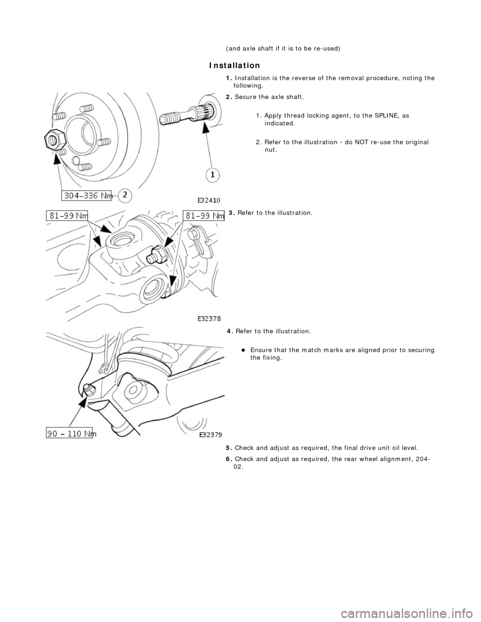
In
stallation
(and axle shaft if i
t
is to be re-used)
1. Installation is the re verse of the removal procedure, noting the
following.
2. Secure the axle shaft.
1.
Apply thread locking agent, to the SPLINE, as
indicated.
2. Refer to the illustration - do NOT re-use the original
nut.
3. Re
fer to the illustration.
4. Re
fer to the illustration.
E
n
sure that the match marks ar
e aligned prior to securing
the fixing.
5. Check and adjust as required, the final drive unit oil level.
6. Check and adjust as required, the rear wheel alignment, 204-
02.
Page 300 of 2490
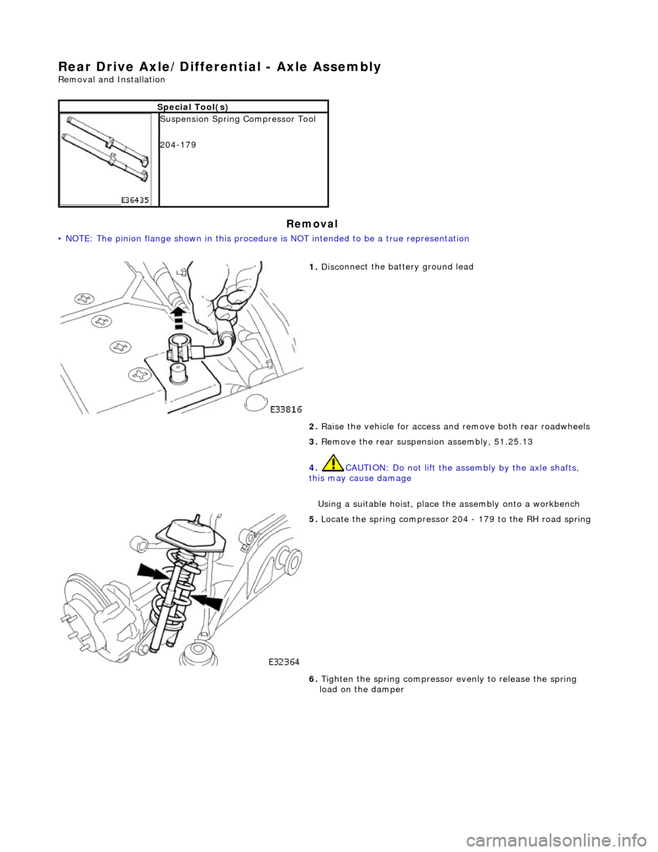
Rea
r Drive Axle/Differential - Axle Assembly
Re
mo
val and Installation
Remov
a
l
•
NOTE: The pinion flange shown in this procedure is NOT intended to be a true representation
S
p
ecial Tool(s)
Suspensi
on
Spring Compressor Tool
204-179
1. Disc
onnect the battery ground lead
2. Raise the vehicle for access and remove both rear roadwheels
3. Remove the rear suspensi on assembly, 51.25.13
4. CAUTION: Do not lift the assembly by the axle shafts,
this may cause damage
Using a suitable hoist, place the assembly onto a workbench
5. Locat e
the spring compressor 204
- 179 to the RH road spring
6. Tighten the spring compressor evenly to release the spring
load on the damper
Page 302 of 2490
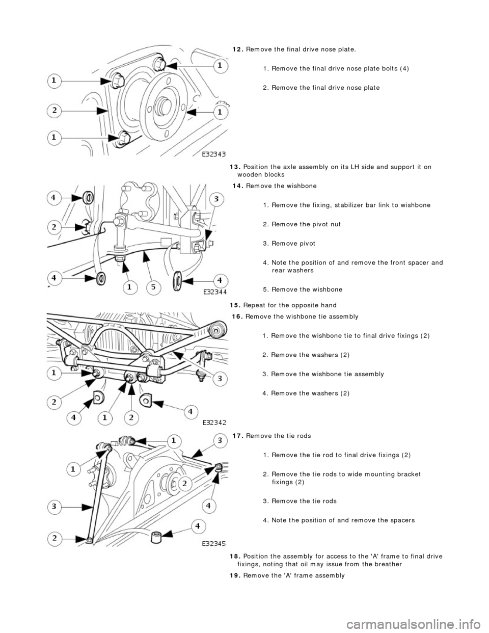
12. R
emove the final dr
ive nose plate.
1. Remove the final drive nose plate bolts (4)
2. Remove the final drive nose plate
13. Position the axle assembly on its LH side and support it on
wooden blocks
14 . Re
move the wishbone
1. Remove the fixing, stabilizer bar link to wishbone
2. Remove the pivot nut
3. Remove pivot
4. Note the position of and remove the front spacer and
rear washers
5. Remove the wishbone
15. Repeat for the opposite hand
16 . R
emove the wishbone tie assembly
1. Remove the wishbone tie to final drive fixings (2)
2. Remove the washers (2)
3. Remove the wishbone tie assembly
4. Remove the washers (2)
17. R
emove the tie rods
1. Remove the tie rod to final drive fixings (2)
2. Remove the tie rods to wide mounting bracket
fixings (2)
3. Remove the tie rods
4. Note the position of and remove the spacers
18. Position the assembly for access to the 'A' frame to final drive
fixings, noting that oil may issue from the breather
19. Remove the 'A' frame assembly