rear axle JAGUAR X308 1998 2.G Service Manual
[x] Cancel search | Manufacturer: JAGUAR, Model Year: 1998, Model line: X308, Model: JAGUAR X308 1998 2.GPages: 2490, PDF Size: 69.81 MB
Page 1383 of 2490

Automatic Transmission/Transaxle - 4.0L NA V8 - AJ27/3.2L NA V8 - AJ26
- Transmission
Installation
Installation
Special Tool(s)
Engine support
303-021
Engine lifting brackets
303-536
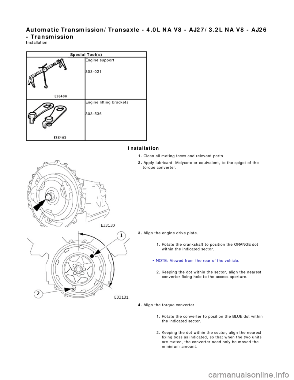
1. Clean all mating faces and relevant parts.
2. Apply lubricant, Molycote or equivalent, to the spigot of the
torque converter.
3. Align the engine drive plate.
1. Rotate the crankshaft to position the ORANGE dot
within the indicated sector.
• NOTE: Viewed from the rear of the vehicle.
2. Keeping the dot within the sector, align the nearest converter fixing hole to the access aperture.
4. Align the torque converter
1. Rotate the converter to position the BLUE dot within the indicated sector.
2. Keeping the dot within the sector, align the nearest fixing boss as indicated, so that when the two units
are mated, the converter need only be moved the
minimum amount.
Page 1388 of 2490

Automatic Transmission/Transaxle - 4.0L SC V8 - AJ26 -
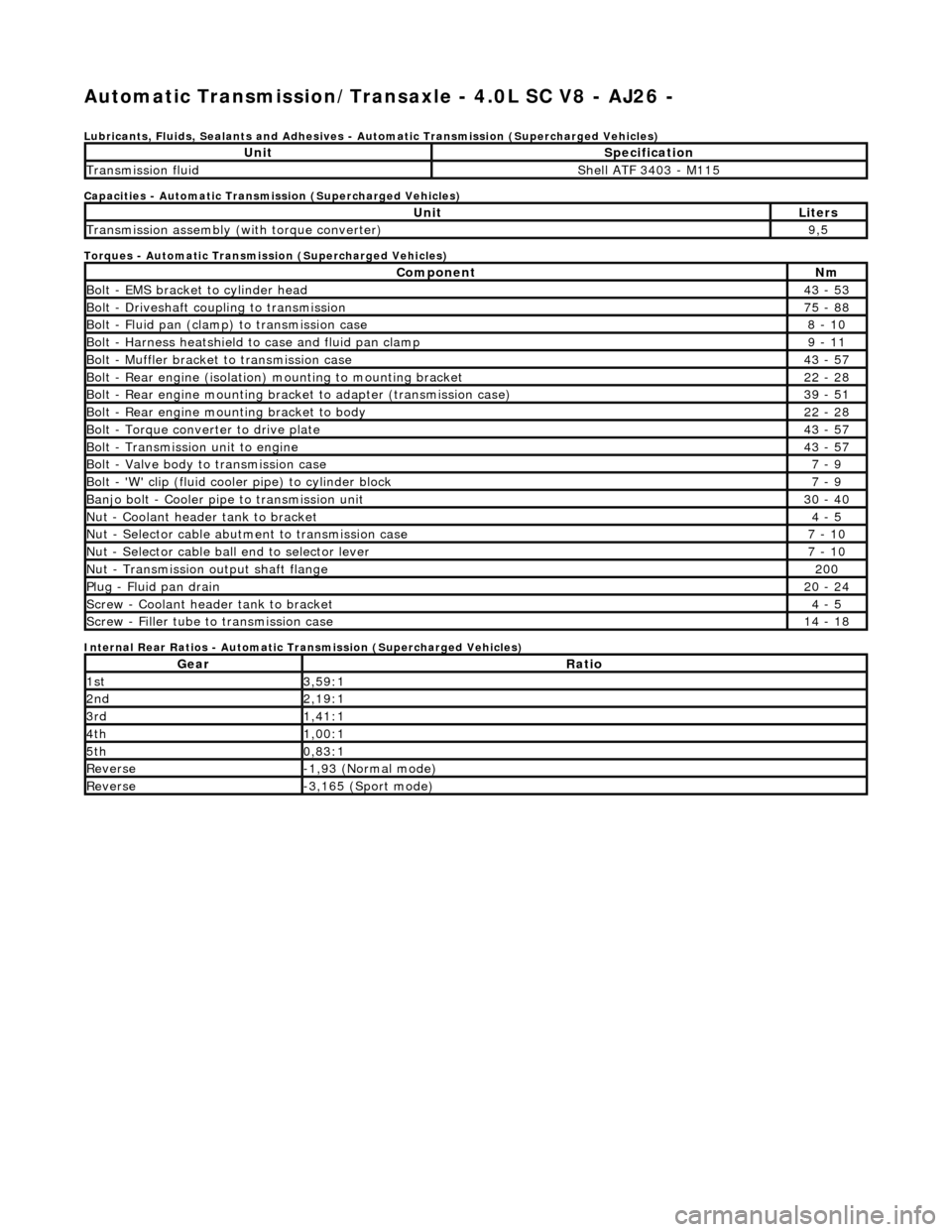
Lubricants, Fluids, Sealants and Adhesives - Automatic Transmission (Supercharged Vehicles)
Capacities - Automatic Transmission (Supercharged Vehicles)
Torques - Automatic Transmission (Supercharged Vehicles)
Internal Rear Ratios - Automatic Transmission (Supercharged Vehicles)
UnitSpecification
Transmission fluidShell ATF 3403 - M115
UnitLiters
Transmission assembly (with torque converter)9,5
ComponentNm
Bolt - EMS bracket to cylinder head43 - 53
Bolt - Driveshaft coupling to transmission75 - 88
Bolt - Fluid pan (clamp) to transmission case8 - 10
Bolt - Harness heatshield to case and fluid pan clamp9 - 11
Bolt - Muffler bracket to transmission case43 - 57
Bolt - Rear engine (isolation) mounting to mounting bracket22 - 28
Bolt - Rear engine mounting brac ket to adapter (transmission case)39 - 51
Bolt - Rear engine mounting bracket to body22 - 28
Bolt - Torque converter to drive plate43 - 57
Bolt - Transmission unit to engine43 - 57
Bolt - Valve body to transmission case7 - 9
Bolt - 'W' clip (fluid cooler pipe) to cylinder block7 - 9
Banjo bolt - Cooler pipe to transmission unit30 - 40
Nut - Coolant header tank to bracket4 - 5
Nut - Selector cable abutment to transmission case7 - 10
Nut - Selector cable ball end to selector lever7 - 10
Nut - Transmission output shaft flange200
Plug - Fluid pan drain20 - 24
Screw - Coolant header tank to bracket4 - 5
Screw - Filler tube to transmission case14 - 18
GearRatio
1st3,59:1
2nd2,19:1
3rd1,41:1
4th1,00:1
5th0,83:1
Reverse-1,93 (Normal mode)
Reverse-3,165 (Sport mode)
Page 1433 of 2490

Automatic Transmission/Transaxle - 4.0L SC V8 - AJ26 - Extension
Housing Seal
In-vehicle Repair
Removal
Special Tool(s)
Oil seal replacer
307-378
Driveshaft wrench
205-053
1. Disconnect the battery ground lead.
2. Select N and choc the road wheels.
3. Remove the front muffler, re fer to Operation 30.10.18.
4. Remove the engine rear mounting bracket.
1. Support the transmission.
2. Remove the bolt, engine rear mounting to transmission.
3. Remove the four bolts which secure the mounting
cross member to the body.
5. Detach the driveshaft from th e transmission drive flange.
1. If the transmission is to be refitted, mark the position of the coupling relative to the drive flange.
5. CAUTION: Under no circ umstances remove the
driveshaft to flexible coupling fixings.
2. Remove the three bolts, tr ansmission drive flange to
flexible coupling.
6. Secure the driveshaft wrench 205 - 053 to the output shaft
flange.
Page 1446 of 2490

Automatic Transmission/Transaxle - 4.0L SC V8 - AJ26 - Transmission
Support Insulator
In-vehicle Repair
Removal
Installation
1. Raise the vehicle on a ramp to a suitable height for working on
the rear mounting.
2. Remove the bolt which secure s the engine rear mounting
rubber to the transmission.
3. Position a transmission jack under the transmission casing.
Take the weight of the transmission on the jack.
4. Remove the rear mounting rubber.
1. Slacken the four bolt s which secure the rear
crossmember to the vehicle floor.
2. Remove the two bolts which secure the mounting rubber to the crossmember.
3. Remove the mounting rubber.
1. Fit the mounting rubber assembly to position and tighten the
centre bolt to 30-40 Nm .
2. Tighten the crossmember to body bolts and the mounting
rubber to crossmember bolts to 22-28 Nm.
Page 1448 of 2490

Automatic Transmission/Transaxle - 4.0L SC V8 - AJ26 - Transmission
Removal
Removal
Special Tool(s)
Engine support
303-021
Engine lifting brackets
303-536
1. Select N gear position.
2. Disconnect the battery ground lead.
3. Remove the engine covers. Re fer to Operation 12.30.06.
4. Remove the air intake tube, MAFM and air cleaner cover
assembly. Refer to Operation 19.10.30.
5. Disconnect the transmission link lead connector.
1. Release the connector fr om its mounting bracket.
2. Disconnect the multiplug.
6. Remove the EMS harness mounting bracket.
Release the bolt, bracket to cylinder head.
7. Fit engine lifting bracket 307 - 536 at the rear RH.
Page 1478 of 2490

Automatic Transmission/Transaxle External Controls - 4.0L NA V8 -
AJ27/3.2L NA V8 - AJ26 - Brake Shift Interlock Actuator Adjustment
General Procedures
1. Disconnect battery ground cable.
Remove the battery cover.
2. Remove the J-gate surround, Section 501-05.
3. Remove the console finisher ve neer panel, Section 501-12.
4. Remove the interlock soleno id actuating lever cover.
5. Move the shift lever to N.
Operate the gearshift interlock latch manually to release
the selector lever from P .
6. NOTE: Assistance from anot her person is required.
Adjust the gearshift interlock solenoid. 1. Slacken the solenoid fixings.
2. Hold the selector lever midway between P and R .
3. Move the solenoid rearwards, against spring pressure, to take up the free play.
4. Tighten the soleno id securing nuts.
5. Ensure that the interloc k actuating lever has no free
play with the selector lever midway between P and
Page 1482 of 2490

Automatic Transmission/Transaxle External Controls - 4.0L NA V8 -
AJ27/3.2L NA V8 - AJ 26 - Selector Lever Cable Adjustment
General Procedures
1. Disconnect battery ground cable.
Remove the battery cover.
2. Position the shift to N.
3. Remove the J-gate surround, Section 501-05.
4. Remove the console finisher ve neer panel, Section 501-12.
5. Remove the center console assembly, Section 501-12.
6. Slacken the selector cable locking nuts away from the
abutment.
7. Raise the vehicle for access.
8. Verify the transmission selector position ( N )
1. At the transmission, detach the inner cable from the selector lever.
2. With the lever moved fully rearward, push the lever forward two detents to achieve N.
3. Reconnect the inner cable.
9. From inside the vehicle.
10. NOTE: When setting the selector cable, ensure that the
transmission selector does not move from the N position.
Adjust the selector cable. 1. Position the shift in the N detent
2. Adjust the nuts to lock against the bracket without
Page 1510 of 2490

Automatic Transmission/Transaxle External Contro ls - 4.0L SC V8 - AJ26 -
Selector Lever Cable Adjustment
General Procedures
1.
Disconnect the vehicle battery ground lead.
2. Position the gear sele ctor lever to N.
3. Remove the J-gate surround, Section 501-05.
4. Remove the console finisher ve neer panel, Section 501-12.
5. Remove the center console assembly, Section 501-12.
6. Slacken the selector cable lock ing nuts and screw them away
from the abutment.
7. Raise the vehicle for access.
8. Verify that the transmis sion selector lever is at position ( N ).
At the transmission, detach the inner cable from the
selector lever.
With the lever moved fully rearward, push the lever
forward two detents to achieve N.
1. Reconnect the inner cable.
9. NOTE: When setting the selector cable, ensure that the
transmission selector does no t move from the (N) position.
Adjust the selector cable from inside the vehicle. 1. Position the gear select or lever to the N detent.
2. Adjust the nuts to lock against the bracket without moving the set position of either the gear selector
lever or the select or lever on the transmission case.
3. Tighten to specification.
4. Verify the ( N ) setting.
10. Further installation is the reve rse of the removal procedure.
Page 1522 of 2490

Exhaust System -
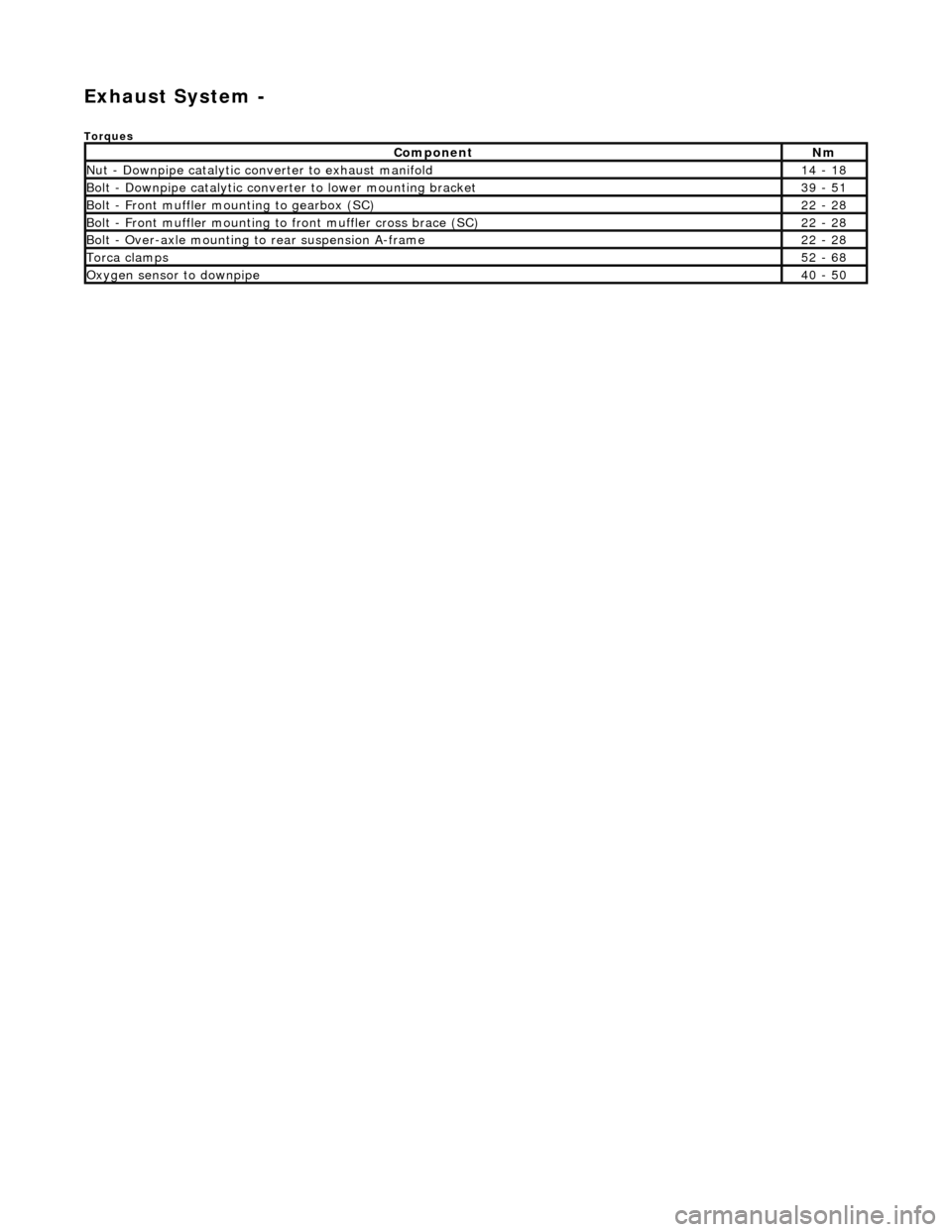
Torques
ComponentNm
Nut - Downpipe catalytic converter to exhaust manifold14 - 18
Bolt - Downpipe catalytic converter to lower mounting bracket39 - 51
Bolt - Front muffler mounting to gearbox (SC)22 - 28
Bolt - Front muffler mounting to front muffler cross brace (SC)22 - 28
Bolt - Over-axle mounting to rear suspension A-frame22 - 28
Torca clamps52 - 68
Oxygen sensor to downpipe40 - 50
Page 1672 of 2490

Exhaust System - Intermediate Muffler LH4.0L NA V8 - AJ27/3.2L NA V8 -
AJ26
Re mo
val and Installation
Remova
l
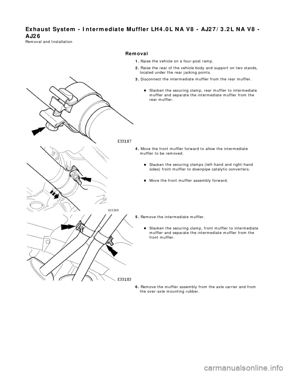
1.
Ra
ise the vehicle on a four-post ramp.
2. Raise the rear of the vehicle bo dy and support on two stands,
located under the re ar jacking points.
3. Disc
onnect the intermediate
muffler from the rear muffler.
Slacken the securi
ng clamp, re
ar muffler to intermediate
muffler and separate the in termediate muffler from the
rear muffler.
4. Move the front muf f
ler forwar
d to allow the intermediate
muffler to be removed.
Sl acke
n the securing clamps (left-hand and right-hand
sides) front muffler to downpipe catalytic converters.
Move the front muf f
ler
assembly forward.
5. Re
move the intermediate muffler.
Sl
acken the securi
ng clamp, front muffler to intermediate
muffler and separate the in termediate muffler from the
front muffler.
6. Remove the muffler assembly from the axle carrier and from
the over-axle mounting rubber.