rear axle JAGUAR X308 1998 2.G Owner's Guide
[x] Cancel search | Manufacturer: JAGUAR, Model Year: 1998, Model line: X308, Model: JAGUAR X308 1998 2.GPages: 2490, PDF Size: 69.81 MB
Page 343 of 2490
Front Disc Brake - Brake CaliperVehicles
With: Standard Brakes
Re
moval and Installation
Remov
al
W
ARNING: BRAKE DUST, IF INHALED CAN DAMAGE YOUR
HEALTH. ALWAYS REMOVE BRAKE DUST USING A VACUUM
BRUSH. DO NOT USE A COMPRESSED-AIR LINE TO DISPERSE BRAKE DUST INTO THE ATMOSPHERE.
• CAUTIONS:
Replacement of nuts and bolts: Various thread-locking de vices are used on nuts and bolts throughout the vehicle.
These devices restrict the number of times a nut or bolt can be used. See section 100-00 for information.
Remove brake fluid spilla ge immediately from paint work, with clean water.
A new brake hose must be installe d when replacing a brake caliper.
The brake pad adhesive backing must not be reused, therefore always install new brake pads, irrespective of the
condition of the original pads when replacing a brake caliper. Always replace brake pads as an axle set.
S
pecial Tool(s)
Brake Pedal
Hold Tool
JDS 9013
1. O
pen engine compartment and fit
paint work protection covers
to fenders.
2. Raise vehicle on a four-post lift.
3. Raise front of vehicle and support on stands. Refer to Section
100-02.
4. Remove front wheels. See Section 204-04.
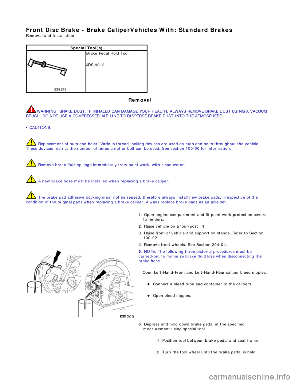
5. NOTE
: The following three pictorial procedures must be
carried-out to minimize brake fl uid loss when disconnecting the
brake hose.
Open Left-Hand-Front and Left-H and-Rear caliper bleed nipples.
Connect
a bleed tube and co
ntainer to the calipers.
O
pen bleed nipples.
6. Depress and hold down brak e pedal at the specified
measurement using special tool.
1. Position tool between brake pedal and seat frame.
2. Turn the tool wheel unti l the brake pedal is held
Page 368 of 2490
Rear Disc Brake - Brake CaliperVehicles W
ith: Standard Brakes
Re
mo
val and Installation
Remov
a
l
WA
RNING: BRAKE DUST, IF INHALED CAN DAMAGE YOUR
HEALTH. ALWAYS REMOVE BRAKE DUST USING A VACUUM
BRUSH. DO NOT USE A COMPRESSED-AIR LINE TO DISPERSE BRAKE DUST INTO THE ATMOSPHERE.
• CAUTIONS:
Replacement of nuts and bolts: Various thread-locking de vices are used on nuts and bolts throughout the vehicle.
These devices restrict the number of times a nut or bolt can be used. See section 100-00 for information.
Remove brake fluid spilla ge immediately from paint work, with clean water.
The brake pad adhesive backing must not be reused, therefore always install new brake pads, irrespective of the
condition of the original pads when replacing a brake caliper. Always replace brake pads as an axle set.
Sp
ecial Tool(s)
Brake Pedal
H
old Tool
JDS 9013
1. Op
en luggage compartment lid and fit suitable paintwork
protection equipment.
2. Raise vehicle on a four-post lift.
3. Raise rear of vehicl e and support on stan ds. See Section 100-
02.
4. Remove rear wheel. See Section 204-04.
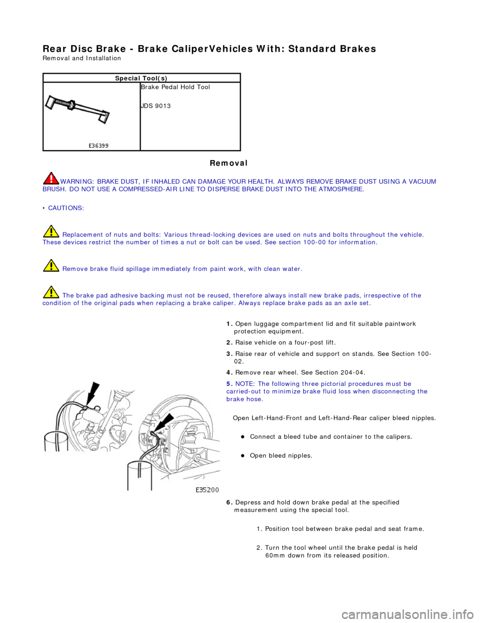
5. NOTE
: Th
e following three pictorial procedures must be
carried-out to minimize brake fl uid loss when disconnecting the
brake hose.
Open Left-Hand-Front and Left-H and-Rear caliper bleed nipples.
Connect a
bleed tube and co
ntainer to the calipers.
Op
en bleed nipples.
6. Depress and hold down brak e pedal at the specified
measurement using the special tool.
1. Position tool between brake pedal and seat frame.
2. Turn the tool wheel unti l the brake pedal is held
60mm down from its released position.
Page 387 of 2490
Rear Dis
c Brake - Brake PadsVehicl
es With: High Performance Brakes
Re
moval and Installation
Remov
al
1.
W
ARNING: BRAKE DUST, IF INHALED CAN DAMAGE
YOUR HEALTH. ALWAYS REMOVE BRAKE DUST USING A VACUUM
BRUSH. DO NOT USE A COMPRE SSED-AIR LINE TO DISPERSE
BRAKE DUST INTO THE ATMOSPHERE. Failure to follow this
instruction may result in personal injury.
• CAUTIONS:
Brake pads must always be replaced in axle sets.
Replacement of nuts and bolts: Various thread-locking
devices are used on nuts and bolts throughout the vehicle. These
devices restrict the number of ti mes a nut or bolt can be used.
For additional information, refer to: General Service Information
(10
0-00 General Information,
Description and Operation).
The High performance brake caliper is aligned to the brake
disc when it is first installed to the vehicle, therefore, care must
be taken not to disturb this alignment. When removing the
caliper; remove the bolts that se cure the anchor bracket to the
vertical link only. DO NOT loosen any other caliper bolts.
Open engine compartment and fit paint work protection covers
to fenders.
2. R
aise rear of vehicle an
d support on stands.
For additional information, refer to: Using the Workshop Jack
(10
0-02 Jacking and Lifting, General Procedures).
3. Remove rear wheels.
For additional information, refer to: Wheel and Tire
(20
4-04
Wheels and Tires, Remo val and Installation).
4. CAUTI
ON: Remove brake flui
d spillage immediately from
paint work, with clean water.
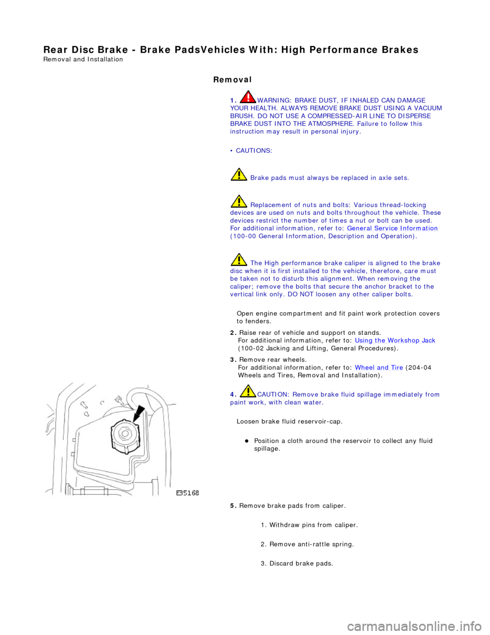
Loosen brake fluid reservoir-cap.
Position a cloth around the
reservoir to collect any fluid
spillage.
5. Remove brake
pads from caliper.
1. Withdraw pins from caliper.
2. Remove anti-rattle spring.
3. Discard brake pads.
Page 1260 of 2490
Automatic Transmission/Transaxle - 4.0L NA V8 - AJ27/3.2L NA V8 - AJ26
-
Lubri c
ants, Fluids, Sealants and Adhesives - ZF Au
tomatic Transmission (Normally Aspirated Vehicles)
Capacities - ZF Automatic Transmission (Normally Aspirated Vehicles)
Torques - ZF Automatic Transmission (Normally Aspirated Vehicles)
Internal Gear Ratios
UnitS p
ecification
Transmissi
on fluidEsso
ATF LT 71141
Torque converter spigotMolyc
o
te or equivalent
UnitLi
t
ers
Transmissi
on fluid (with
torque converter)
10
,0
Com p
onent
Nm
Locki
n
g ferrule - Shift knob
7 -
10
P
l
ug - Drain fluid pan
27
-
33
P
l
ug - Level / fill (transmission case M18 x 1.5)
32
-
38
Tu
be
nut - Cooler pipe to transmission unit
17
-
23
B
o
lt - Drive plate to torque converter
43
-
57
B
o
lt - Driveshaft coupling to transmission
75
-
88
Bo
lt
- Fluid filter to valve block
4,
5 -
5,5
Bolt
-
Fluid pan to transmission case
9 -
11
B
o
lt - Rear extension housing to transmission case
21
-
25
Bolt
-
Rear engine (isolation) mounting to mounting bracket
22
-
28
Bolt -
Rear engine moun
ting bracket to body
22
-
28
Bolt
-
Rear engine mounting bracke
t to transmission rear extension
30 -
40
B
o
lt - Selector cable bracket to transmission case
7 -
10
Bolt
-
Transmission unit to engine
43
-
57
Nu
t -
Transmission drive flange
1
08 -
132
Nu
t -
Selector cable inner to shift lever
1,
5 -
2,5
Nu
t -
Selector cable inner to selector lever
7 -
10
Nu
t -
Selector cable outer to bracket
22
-
28
Nu
t
- Selector lever pivot shaft
7 -
10
Nu
t -
Shift interlock solenoid to housing
5 -
7
Nut -
Shift interlock solenoid actuating lever
11
-
13
Sc
re
w - Input sensor bracket to transmission case (M5)
4,
5 -
5,5
Screw
-
Output sensor bracket to transmission case (M6)
7,
5 -
8,5
Screw
-
Solenoid / regulator plate to valve body
4,
5 -
5,5
Sc
re
w - Valve block to transmission case
7,
5 -
8,5
GearRatio
1s
t3,57
1:1
2n
d2,2:
1
3r
d1,50
8:1
4t
h1,00
:1
5t
h0,80
3:1
Re
ve
rse
4,
06
3:1
Page 1339 of 2490

Automatic Transmission/Transaxle - 4.0L NA V8 - AJ27/3.2L NA V8 - AJ26
- Electronic Pressure Control (EPC) Solenoid
In-vehicle Repair
Removal
1. Disconnect battery ground cable.
Remove the battery cover.
2. Raise the vehicle on a suitable lift.
2. WARNING: TRANSMISSION FLUID MAY CAUSE
SEVERE BURNS, ENSURE THAT ALL SAFETY PROCEDURES
ARE OBSERVED.
Carefully remove the drain plug and drain the
transmission fluid.
3. Remove the twenty-two fixings which secure the fluid pan .
Remove the fluid pan and all traces of gasket material.
4. Disconnect regulator / solenoid connectors.
5. Remove RH rear valve body securing screws.
Page 1342 of 2490
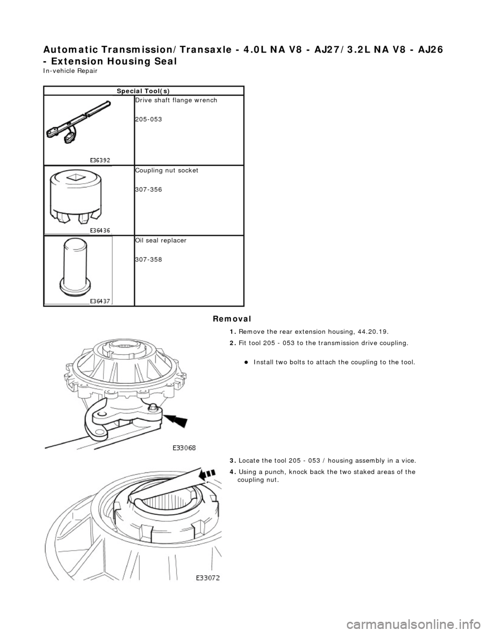
Automatic Transmission/Transaxle - 4.0L NA V8 - AJ27/3.2L NA V8 - AJ26
- Extension Housing Seal
In-vehicle Repair
Removal
Special Tool(s)
Drive shaft flange wrench
205-053
Coupling nut socket
307-356
Oil seal replacer
307-358
1. Remove the rear extension housing, 44.20.19.
2. Fit tool 205 - 053 to the transmission drive coupling.
Install two bolts to attach the coupling to the tool.
3. Locate the tool 205 - 053 / housing assembly in a vice.
4. Using a punch, knock back the two staked areas of the
coupling nut.
Page 1345 of 2490

Automatic Transmission/Transaxle - 4.0L NA V8 - AJ27/3.2L NA V8 - AJ26
- Extension Housing O-Ring Seal
In-vehicle Repair
Removal
1. Select N position.
2. Raise the vehicle for access.
3. Remove the front muffler, 30.10.18.
4. Locate a transmission jack, Epco V-100 or similar, under the
transmission unit.
Adjust the angle of the jack to suit the transmission.
Secure the side clamps.
Pass the safety chain over the transmission unit and
secure.
Take the weight of the transmission and engine.
5. Remove the engine rear mounting bracket.
1. Remove the engine rear mounting to bracket bolt.
2. Remove the mounting bracket to body bolts.
6. Gently lower the transmission jack.
7. CAUTION: Under no circumstan ces remove the driveshaft
to flexible coupling fixings.
Detach the driveshaft fro m the transmission unit.
Mark the position of the coupling to drive flange.
Remove the three bolts which secure the transmission
drive flange to the flexible coupling .
8. Remove the rear extension housing assembly.
1. Remove the ten bolts, noting their location for installation.
2. Remove and discard the O-ring.
Page 1354 of 2490

Automatic Transmission/Transaxle - 4.0L NA V8 - AJ27/3.2L NA V8 - AJ26
- Shift Solenoids (SS)
In-vehicle Repair
Removal
1. Disconnect battery ground cable.
Remove the battery cover.
2. Raise the vehicle on a lift.
2. WARNING: TRANSMISSION FLUID MAY CAUSE
SEVERE BURNS, ENSURE THAT ALL SAFETY PROCEDURES
ARE OBSERVED.
Carefully remove the drain plug and drain the
transmission fluid.
3. Remove the twenty-two bolts which secure the fluid pan.
Remove the fluid pan and all tr aces of gasket material.
4. Disconnect the eight soleno id / regulator connectors.
5. Remove the RH rear valve body securing screws.
Page 1371 of 2490

Automatic Transmission/Transaxle - 4.0L NA V8 - AJ27/3.2L NA V8 - AJ26
- Transmission Support Insulator
In-vehicle Repair
Removal
Installation
1. Raise the vehicle on a ramp to a suitable height for working on
the rear mounting.
2. Remove the bolt which secure s the engine rear mounting
rubber to the transmission.
3. Position a transmission jack under the transmission casing.
Take the weight of the transmission on the jack.
4. Remove the rear mounting rubber.
1. Slacken the four bolt s which secure the rear
crossmember to the vehicle floor.
2. Remove the two bolts which secure the mounting rubber to the crossmember.
3. Remove the mounting rubber.
1. Fit the mounting rubber assembly to position and tighten the
centre bolt to 30-40 Nm .
2. Tighten the crossmember to body bolts and the mounting
rubber to crossmember bolts to 22-28 Nm.
Page 1375 of 2490

Automatic Transmission/Transaxle - 4.0L NA V8 - AJ27/3.2L NA V8 - AJ26
- Transmission
Removal
Removal
Special Tool(s)
Engine support
303-021
Engine lifting brackets
303-536
1. Select N gear position.
2. Open the engine compartment and fit paintwork protection
sheets.
3. Disconnect battery ground cable.
Remove the battery cover.
4. Remove the engine covers (12.30.06).
5. Remove the air intake tube, MAFM and air cleaner cover assy,
(19.10.30).
6. Install engine lifting bracket 303 - 536 at the rear RH.
7. Reposition the coolant he ader tank for access.
1. Remove the securing bolt.