rear axle JAGUAR X308 1998 2.G Repair Manual
[x] Cancel search | Manufacturer: JAGUAR, Model Year: 1998, Model line: X308, Model: JAGUAR X308 1998 2.GPages: 2490, PDF Size: 69.81 MB
Page 1674 of 2490
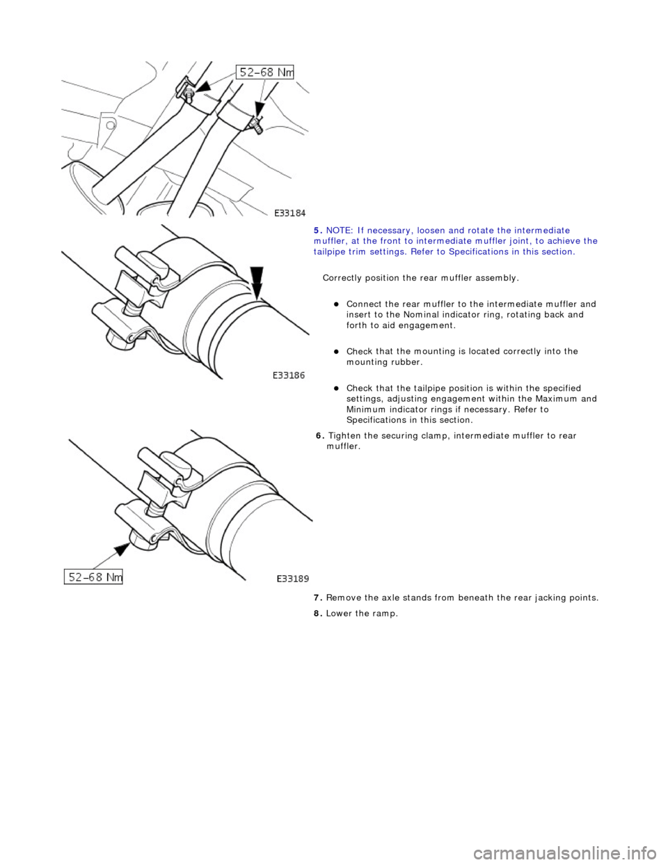
5.
NO TE
: If necessary, loosen and rotate the intermediate
muffler, at the front to intermediate muffler joint, to achieve the
tailpipe trim settings. Refer to Specifications in this section.
Correctly position the rear muffler assembly.
Connect the rear muffl
er to the intermediate muffler and
insert to the Nominal indicator ring, rotating back and
forth to aid engagement.
Chec k
that the mounting is located correctly into the
mounting rubber.
Chec k
that the tailpi
pe position is wi thin the specified
settings, adjusting engageme nt within the Maximum and
Minimum indicator rings if necessary. Refer to
Specifications in this section.
6. Tigh te
n the securing clamp, in
termediate muffler to rear
muffler.
7. Remove the axle stands from be neath the rear jacking points.
8. Lower the ramp.
Page 1675 of 2490
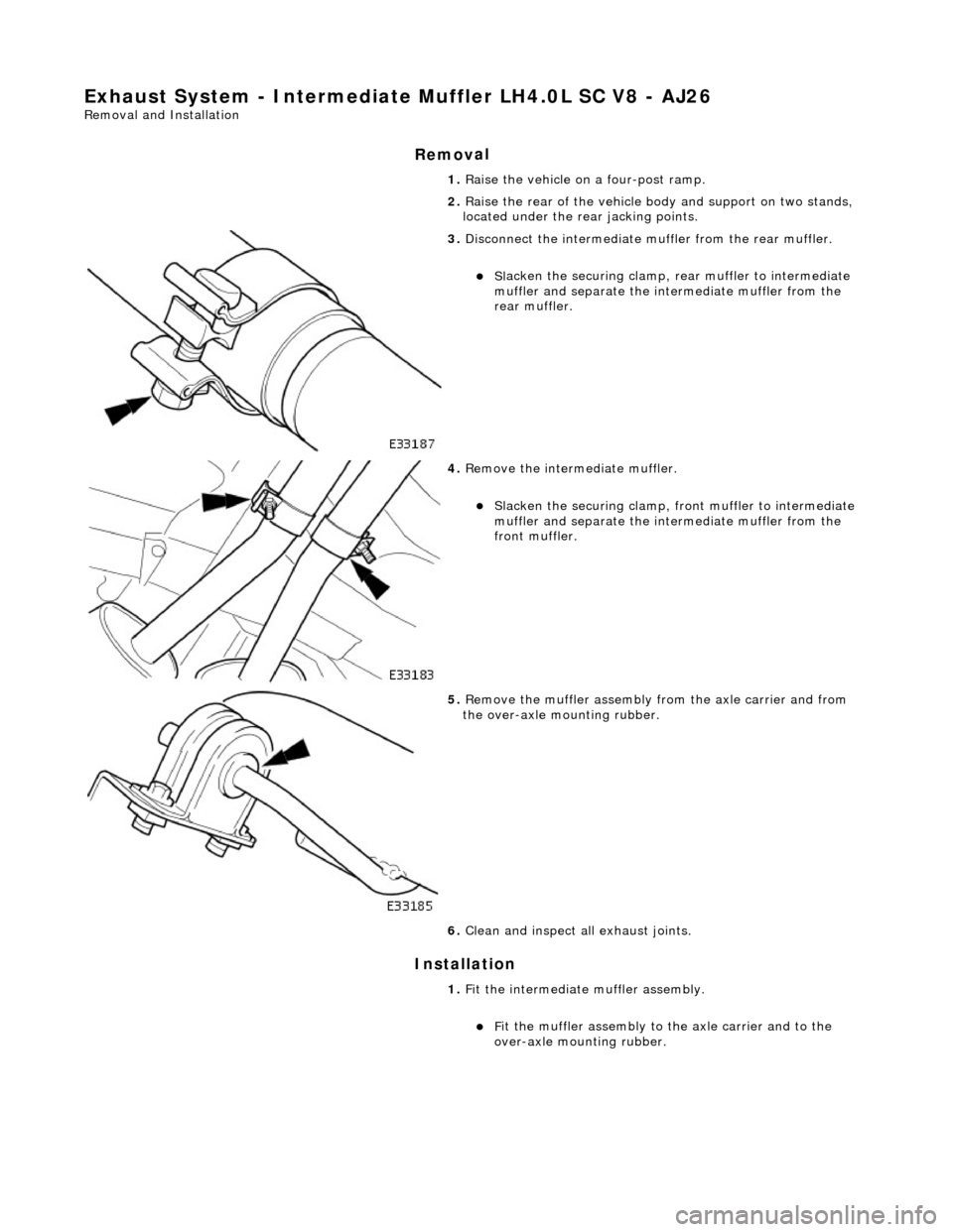
Exhaust System - Intermediate Muffler LH4
.0L SC V8 - AJ26
Re
moval and Installation
Remov
al
Installation
1. R
aise the vehicle on a four-post ramp.
2. Raise the rear of the vehicle bo dy and support on two stands,
located under the re ar jacking points.
3. Di
sconnect the intermediate
muffler from the rear muffler.
Sl
acken the securing clamp, re
ar muffler to intermediate
muffler and separate the in termediate muffler from the
rear muffler.
4. R
emove the intermediate muffler.
Sl
acken the securing clamp, front muffler to intermediate
muffler and separate the in termediate muffler from the
front muffler.
5. R
emove the muffler assembly
from the axle carrier and from
the over-axle mounting rubber.
6. Clean and inspect al l exhaust joints.
1. Fit the intermediate muffler assembly.
F
it the muffler assembly to the axle carrier and to the
over-axle mounting rubber.
Page 1677 of 2490
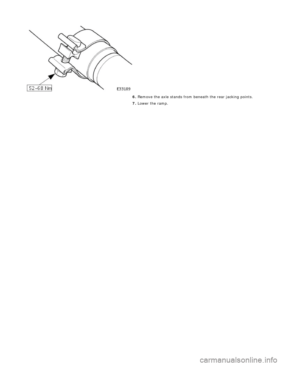
6.
R
emove the axle stands from be
neath the rear jacking points.
7. Lower the ramp.
Page 1678 of 2490
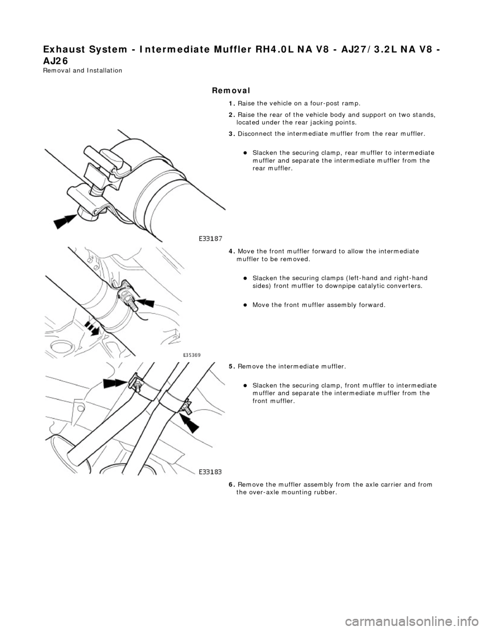
Exhaust System - Intermediate Muffler RH4.0L NA V8 - AJ27/3.2L NA V8 -
AJ26
Re mo
val and Installation
Remova
l
1.
Ra
ise the vehicle on a four-post ramp.
2. Raise the rear of the vehicle bo dy and support on two stands,
located under the re ar jacking points.
3. Disc
onnect the intermediate
muffler from the rear muffler.
Slacken the securi
ng clamp, re
ar muffler to intermediate
muffler and separate the in termediate muffler from the
rear muffler.
4. Move the front muf f
ler forwar
d to allow the intermediate
muffler to be removed.
Sl acke
n the securing clamps (left-hand and right-hand
sides) front muffler to downpipe catalytic converters.
Move the front muf f
ler
assembly forward.
5. Re
move the intermediate muffler.
Sl
acken the securi
ng clamp, front muffler to intermediate
muffler and separate the in termediate muffler from the
front muffler.
6. Remove the muffler assembly from the axle carrier and from
the over-axle mounting rubber.
Page 1680 of 2490
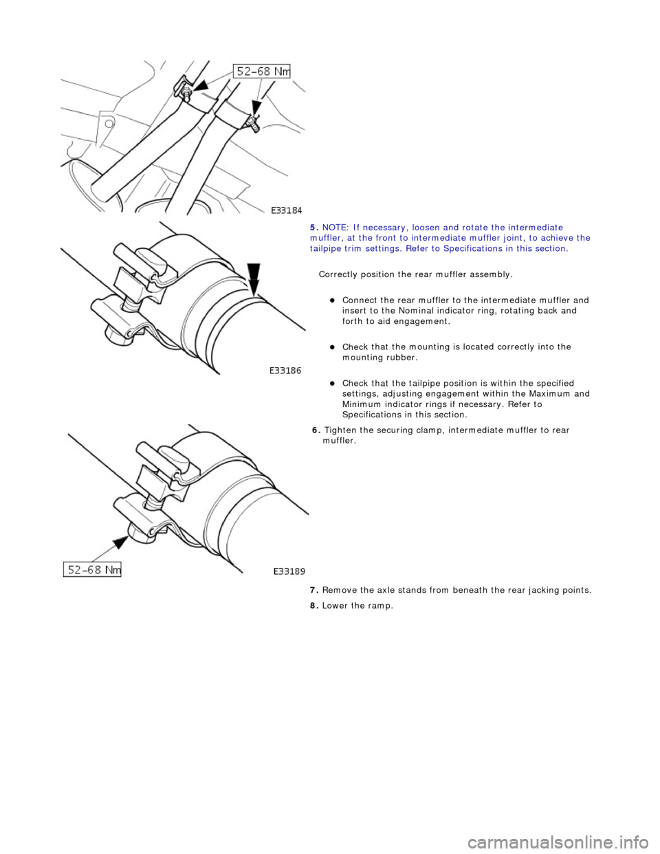
5.
NO TE
: If necessary, loosen and rotate the intermediate
muffler, at the front to intermediate muffler joint, to achieve the
tailpipe trim settings. Refer to Specifications in this section.
Correctly position the rear muffler assembly.
Connect the rear muffl
er to the intermediate muffler and
insert to the Nominal indicator ring, rotating back and
forth to aid engagement.
Chec k
that the mounting is located correctly into the
mounting rubber.
Chec k
that the tailpi
pe position is wi thin the specified
settings, adjusting engageme nt within the Maximum and
Minimum indicator rings if necessary. Refer to
Specifications in this section.
6. Tigh te
n the securing clamp, in
termediate muffler to rear
muffler.
7. Remove the axle stands from be neath the rear jacking points.
8. Lower the ramp.
Page 1681 of 2490

Exhaust System - Intermediate Muffler RH4
.0L SC V8 - AJ26
Re
moval and Installation
Remov
al
Installation
1. R
aise the vehicle on a four-post ramp.
2. Raise the rear of the vehicle bo dy and support on two stands,
located under the re ar jacking points.
3. Di
sconnect the intermediate
muffler from the rear muffler.
Sl
acken the securing clamp, re
ar muffler to intermediate
muffler and separate the in termediate muffler from the
rear muffler.
4. R
emove the intermediate muffler.
Sl
acken the securing clamp, front muffler to intermediate
muffler and separate the in termediate muffler from the
front muffler.
5. R
emove the muffler assembly
from the axle carrier and from
the over-axle mounting rubber.
6. Clean and inspect al l exhaust joints.
1. Fit the intermediate muffler assembly.
F
it the muffler assembly to the axle carrier and to the
over-axle mounting rubber.
Page 1683 of 2490

6.
R
emove the axle stands from be
neath the rear jacking points.
7. Lower the ramp.
Page 1734 of 2490
Fuel Tank and Lines - Fuel Tank
Re
mo
val and Installation
Remov
a
l
•
NO
TE: This removal/installation procedure is applicable to all tank assembly variants.
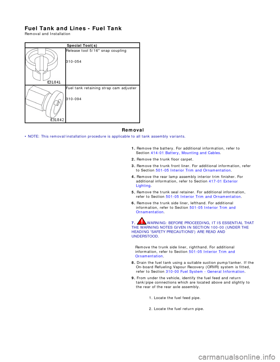
S
p
ecial Tool(s)
R
e
lease tool 5/16" snap coupling
310-054
F u
el tank retaining strap cam adjuster
310-094
1. Remove the battery. For additi onal information, refer to
Section 414
-01
Battery, Mounting and Cables
.
2. Re
move the trunk floor carpet.
3. Remove the trunk front liner. Fo r additional information, refer
to Section 501
-05
Interior Trim and Ornamentation
.
4. Re
move the rear lamp assembly interior trim finisher. For
additional information, refer to Section 417
-01
Exterior
Ligh
ting.
5. Re
move the trunk seal retainer
. For additional information,
refer to Section 501
-0 5
Interior Trim and Ornamentation
.
6. Re
move the trunk side liner, lefthand. For additional
information, refer to Section 501
-05
Interior Trim and
Or
n
amentation
.
7. WARNING: B E
FORE PROCEEDING, IT IS ESSENTIAL THAT
THE WARNING NOTES GIVEN IN SECTION 100-00 (UNDER THE
HEADING 'SAFETY PRECAUTIONS') ARE READ AND
UNDERSTOOD.
Remove the trunk side liner, righthand. For additional
information, refer to Section 501
-05
Interior Trim and
Or
n
amentation
.
8.
Drain th e fue
l tank using a suitab
le suction pump/tanker. If the
On-board Refueling Vapour Recove ry (ORVR) system is fitted,
refer to Section 310
-00 Fu
el System
- General
Information
.
9. Fr
om under the vehicle, identify the fuel feed and return
tank/pipe connections which are located above and slightly to
the rear of the rear axle assembly.
1. Locate the fuel feed pipe.
2. Locate the fuel return pipe.
Page 1743 of 2490
Accelerati
on Control - Accelerator Cable Adjustment
Gen
eral Procedures
1.
Load the Approved Jaguar Diagno stic System with power train
data logger.
2. Connect the Approved Jaguar Diag nostic System to the vehicle.
3. W
ith 'Disable Network Integrity Test - YES/ NO' displayed on
the screen select YES.
4. With new menu displayed on the screen, select ' Engine
Management'.
5. Turn the ignition to ON.
R
emove any previously selected data logger parameters.
6. On data logger select PPS11 an d PPS2 (Pedal demand sensors
1 and 2).
7. On Sedan models only, remove the bulkhead covers on both
sides and the engine compartment rear cover.
8. Cut, remove and discard the ra tchet strap which retains the
throttle cable to the abutment bracket.
9. Ensure there is no tension on the throttle cable by releasing
the throttle cable adjustment nut from the abutment bracket.
10. Record the voltages for both sensors, PPS11 and PPS2.
11. Partially insert the throttle cable adjustment nut into the
abutment bracket.
12. Recheck the voltages for both sensors, PPS11 and PPS2.
13. Where the voltages at step 12 are higher than the voltages
taken at step 10, contin ue to step 15 below.
14. Where the voltages at step 12 are the same as the voltages
taken at step 10, contin ue to step 16 below.
15. Rotate the adjustment nut clockwise (as viewed from the
front of the vehicle) until the same voltages are indicated as in
step 10. Continue to turn thro ugh a part revolution until the
sides of the nut are vertical. Tu rn through a further 90 degrees,
then fully insert the nut into the abutment bracket.
16. Rotate the adjustment nut anti-clockwise (as viewed from the
front of the vehicle) until the indicated voltage starts to
increase. Then rotate the nut clockwise through a part
revolution until the sides are ve rtical. Turn through a further 90
degrees, then fully insert the nut into the abutment bracket.
17. Fit a new ratchet strap to secure the throttle cable adjusting
nut to the abutment bracket.
18. Operate the throttle pedal through 20 full cycles to settle the
cable. Check the voltages now shown, remain the same as in
steps 15 and 16.
19. Check and where necessary adjust the kickdown switch. For
additional information, refer to Section 307
-05A Automatic Transmissi
on/Transaxle External Controls
Sectio
n
307
-05
B
Au
tomatic Transmission/Tra
nsaxle External Controls
.
20
.
On Sedan models only, refit the engine compartment rear
cover and the bulkhead co vers on both sides.
21. Switch the ignition OFF and disconnect the Approved Jaguar
Diagnostic System.
Page 1975 of 2490
Location of J1962 socket
The J1962 socket is located at the driver side inboard footwell.
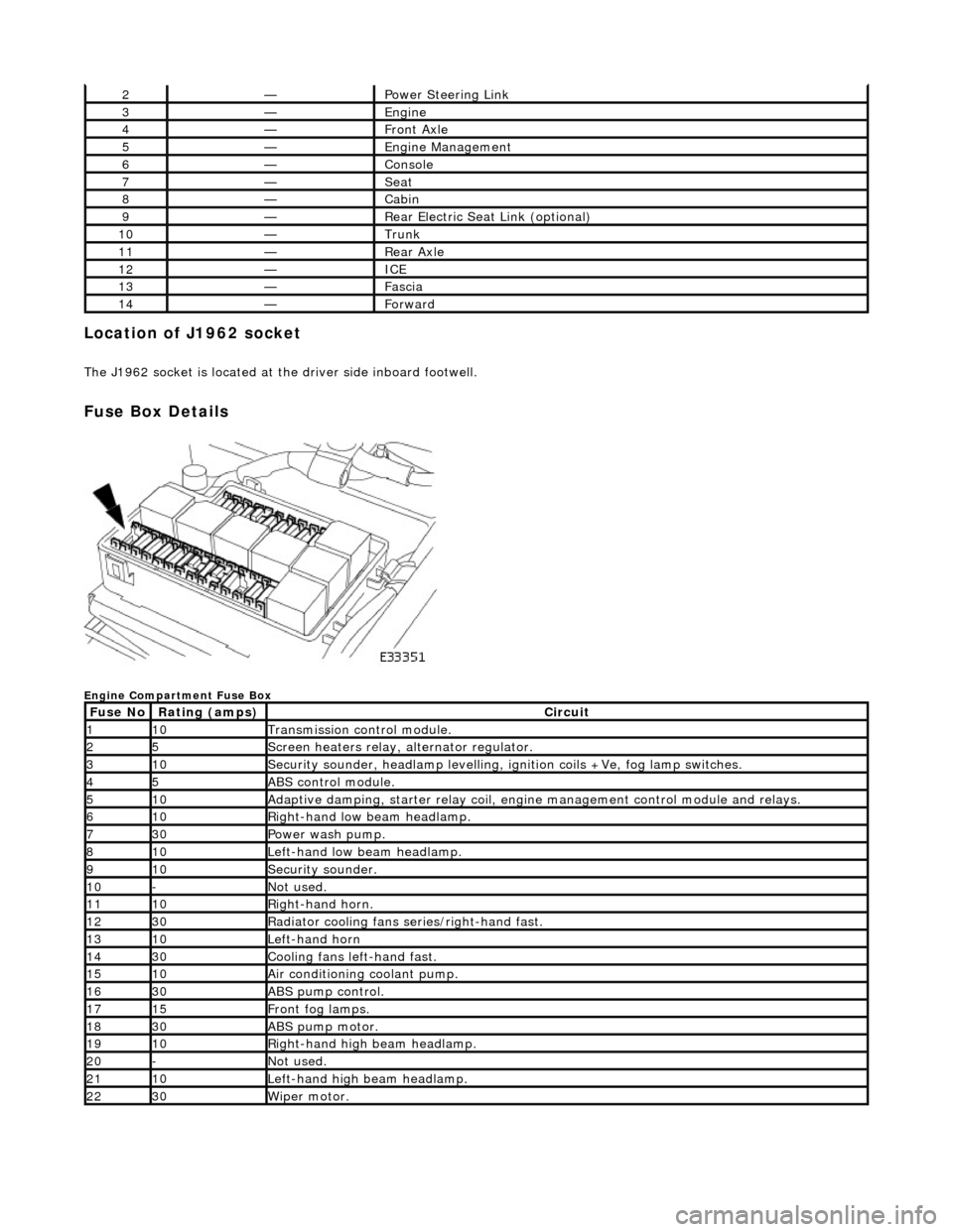
Fuse Box Details
Engine Compartment Fuse Box
2—Power Steering Link
3—Engine
4—Front Axle
5—Engine Management
6—Console
7—Seat
8—Cabin
9—Rear Electric Seat Link (optional)
10—Trunk
11—Rear Axle
12—ICE
13—Fascia
14—Forward
Fuse NoRating (amps)Circuit
110Transmission control module.
25Screen heaters relay, alternator regulator.
310Security sounder, headlamp levelling, ignition coils +Ve, fog lamp switches.
45ABS control module.
510Adaptive damping, starter relay coil, engine management control module and relays.
610Right-hand low beam headlamp.
730Power wash pump.
810Left-hand low beam headlamp.
910Security sounder.
10-Not used.
1110Right-hand horn.
1230Radiator cooling fans series/right-hand fast.
1310Left-hand horn
1430Cooling fans left-hand fast.
1510Air conditioning coolant pump.
1630ABS pump control.
1715Front fog lamps.
1830ABS pump motor.
1910Right-hand high beam headlamp.
20-Not used.
2110Left-hand high beam headlamp.
2230Wiper motor.