speaker JAGUAR X308 1998 2.G Owner's Manual
[x] Cancel search | Manufacturer: JAGUAR, Model Year: 1998, Model line: X308, Model: JAGUAR X308 1998 2.GPages: 2490, PDF Size: 69.81 MB
Page 2075 of 2490

Installation
1. Release puddle lamp harness from clips at base of door pocket.
2. Slacken and remove th e two screws securing
bottom of pocket to casing.
3. Remove two spring clips securing top of pocket to casing.
14. Lift pocket from casing.
15. Slacken and remove door sp eaker securing screws and
remove speaker from casing.
1. Fit and fully seat casing securing clips.
2. Position speaker grill in casing align speaker and fit and tighten
securing screws.
3. Position pocket in casing and secure with screws and spring
clips.
4. Fit puddle lamp to casing, fit and tighten securing screws and
position harness in pocket clips.
5. Fit door armrest to casing. Refer to 76.34.23.
6. Fit inner waist seal holder to casing and fit and tighten the
securing screws.
7. Align and fit inner waist seal.
8. Fit door armrest to casing. Refer to .
9. Check that armrest tang locater and screw insert are correctly
positioned in door panel.
10. Position casing for access and connect tweeter, speaker,
puddle lamp and switchpack harnesses.
11. Finally position casing locating fold over waist flange and
firmly press armrest to locate retaining tang in door panel.
12. Commencing at front , press and firmly seat casing lower
fasteners in door inserts.
13. Fit and tighten armrest centre se curing screw in door insert.
14. Fit door casing veneer panel. Refer to 76.47.11.
15. Position door handle escutche on on casing, fit and tighten
securing screw and fit cover over screw.
Page 2092 of 2490

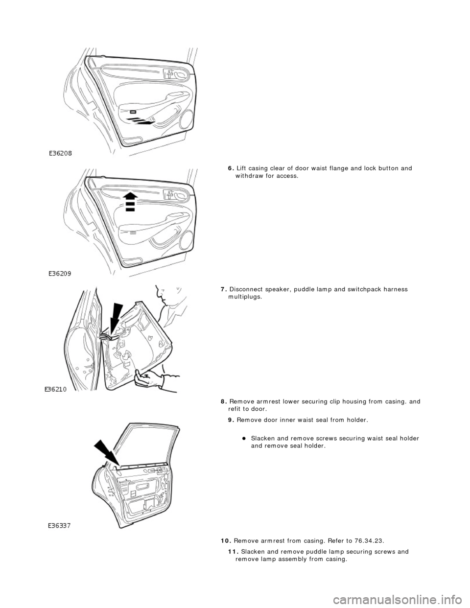
6. Lift casing clear of door wais t flange and lock button and
withdraw for access.
7. Disconnect speaker, puddle lamp and switchpack harness
multiplugs.
8. Remove armrest lower securing clip housing from casing. and
refit to door.
9. Remove door inner waist seal from holder.
пЃ¬Slacken and remove screws securing waist seal holder
and remove seal holder.
10. Remove armrest from casing. Refer to 76.34.23.
11. Slacken and remove puddle la mp securing screws and
remove lamp assembly from casing.
Page 2093 of 2490

Installation
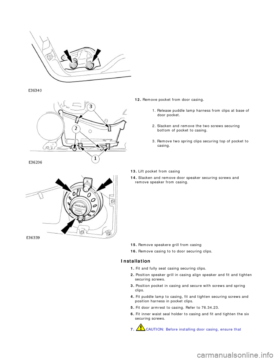
12. Remove pocket from door casing.
1. Release puddle lamp harness from clips at base of door pocket.
2. Slacken and remove th e two screws securing
bottom of pocket to casing.
3. Remove two spring clips securing top of pocket to casing.
13. Lift pocket from casing
14. Slacken and remove door sp eaker securing screws and
remove speaker from casing.
15. Remove speakere grill from casing
16. Remove casing to to door securing clips.
1. Fit and fully seat casing securing clips.
2. Position speaker grill in casing align speaker and fit and tighten
securing screws.
3. Position pocket in casing and secure with screws and spring
clips.
4. Fit puddle lamp to casing, fit and tighten securing screws and
position harness in pocket clips.
5. Fit door armrest to casing. Refer to 76.34.23.
6. Fit inner waist seal holder to casing and fit and tighten the six
securing screws.
7. CAUTION: Before installing door casing, ensure that
Page 2094 of 2490

primary water shedder is undamag
ed and correctly attached to
door inner panel.
Align and fit inner waist seal.
8. Check that armrest tang locater and screw insert are correctly
positioned in door panel.
9. Position casing for access and connect speaker, puddle lamp
and switchpack harnesses.
10. Finally position casing locating fold over waist flange and
firmly press armrest to locate retaining tang in door panel.
11. Commencing at front , press and firmly seat casing lower
fasteners in door inserts
12. Fit and tighten armrest centre se curing screw in door insert.
13. Fit door veneer panel. Refer to 76.47.12.
14. Position door handle escutche on on casing, fit and tighten
securing screw and fit cover over screw.
Page 2242 of 2490

Instrument Panel and Console - Instrument Panel
Removal and Installation
Removal
1. Turn ignition switch to position II.
2. Motor driver and front passenger seats rearward.
3. Position steering wheel in stra ight ahead position and fully
lower and extend steering column.
4. Turn ignition switch to position O.
5. Remove battery cover and disc onnect ground cable from
battery terminal. Refer to 86.15.19.
6. Remove 'J' gate finish er. Refer to 76.25.24.
7. Remove 'J' gate finisher retain ing panel. Refer to 76.25.26.
8. Remove centre console veneer panel. Refer to 76.47.26.
9. Disconnect and remove radio.
10. Remove centre console switch module. Refer to 86.80.32.
11. Remove centre console. Refer to 76.25.01.
12. Slacken and remove centre cons ole vent duct rear securing
screw and withdraw duct assemb ly from air conditioning unit
manifold.
13. WARNING: BEFORE ANY AIRBAG/SRS SERVICE IS
PERFORMED, AT LEAST ONE MINUTE MUST ELAPSE AFTER
DISCONNECTION OF THE BATTERY CABLE, TO ALLOW
DISSIPATION OF BACK-UP POWER SUPPLY ENERGY.
Remove driver airbag. Refer to 76.73.39.
14. Remove steering wheel. Refer to Section 211-04.
15. Remove steering column lo wer cowl. Refer to 76.46.03.
16. Remove steering column u pper cowl. Refer to 76.46.02.
17. Remove driver side unders cuttle. Refer to 76.46.11.
18. Remove combined windshield wiper/washer switch and
audible warning speaker assembly. Refer to 86.65.42.
19. Remove glovebox. Refer to 76.52.03.
20. Remove 'A' post lower trim pads. refer to 76.13.30.
21. Carefully withdraw driver stowage bin trim, remove bin
securing screw and remove bin from facia.
Page 2263 of 2490

64.
Position driver stowage bin in facia, install securing screw and fully seat trim.
65. Install trim pad on driver si de lower 'A' post. Refer to
76.13.30.
66. Install driver side unders cuttle. Refer to 76.46.11.
67. Install combined windshield wi per/washer switch and audible
warning speaker assembly. Refer to 86.65.42.
68. Install steering column upper cowl. Refer to 76.46.02.
69. Install steering column lower cowl. Refer to 76.46.03.
70. Install steering wheel. Refer to 211-04.
71. Install driver side airbag. Refer to 76.73.39.
Page 2325 of 2490

Installation
18. Remove windshield wiper/ washer switch/mounting
bracket/audible warning speaker assembly from vehicle.
1. Position windshield wipe r/washer switch/mounting
bracket/audible warning speaker assembly for access in
vehicle.
2. Fit cancellation module to mounting bracket.
3. Fit wiper/washer switch to cancellation module/mounting
bracket.
4. Fit flasher/lamp/trip switch to cancellation module/mounting
bracket.
5. Position switchgear assembly on steering column and fit and
tighten securing bolts.
6. Connect cancellation module harness multiplugs and fit
multiplugs to retaining bracket.
7. Connect flasher/lamp/trip switch harness multiplugs and fit
multiplugs to retaining bracket.