tank JAGUAR X308 1998 2.G Owner's Manual
[x] Cancel search | Manufacturer: JAGUAR, Model Year: 1998, Model line: X308, Model: JAGUAR X308 1998 2.GPages: 2490, PDF Size: 69.81 MB
Page 958 of 2490
Engine Cooling - Cooling System Draining and Vacuum Filling
Gene
ral Procedures
WARNING: To avoid having scalding ho t coolant or steam blowing out of the cooling system, use extreme care when
removing the coolant pressure cap from a hot cooling system. Wait until the engine has cooled, then wrap a thick cloth
around the coolant pressure cap and turn it slowly until the pressure begins to release. Step ba ck while the pressure is
released from the system. When certain al l the pressure has been released (still with a cloth) turn and remove the coolant
pressure cap from the coolant expansion tank. Failure to fo llow these instructions may result in personal injury.
• CAUTIONS:
The engine cooling syst em must be maintained with the correct concentration and type of anti-freeze solution to
prevent corrosion and frost damage. Failure to follow th is instruction may result in damage to the vehicle.
Engine coolant will damage the paint finished surfaces. If spilt, immediately remove the coolant and clean the area
with water.
• NOTE: Vehicles fitted with supercharged engines shown, V8 NA engines similar.
All vehicles
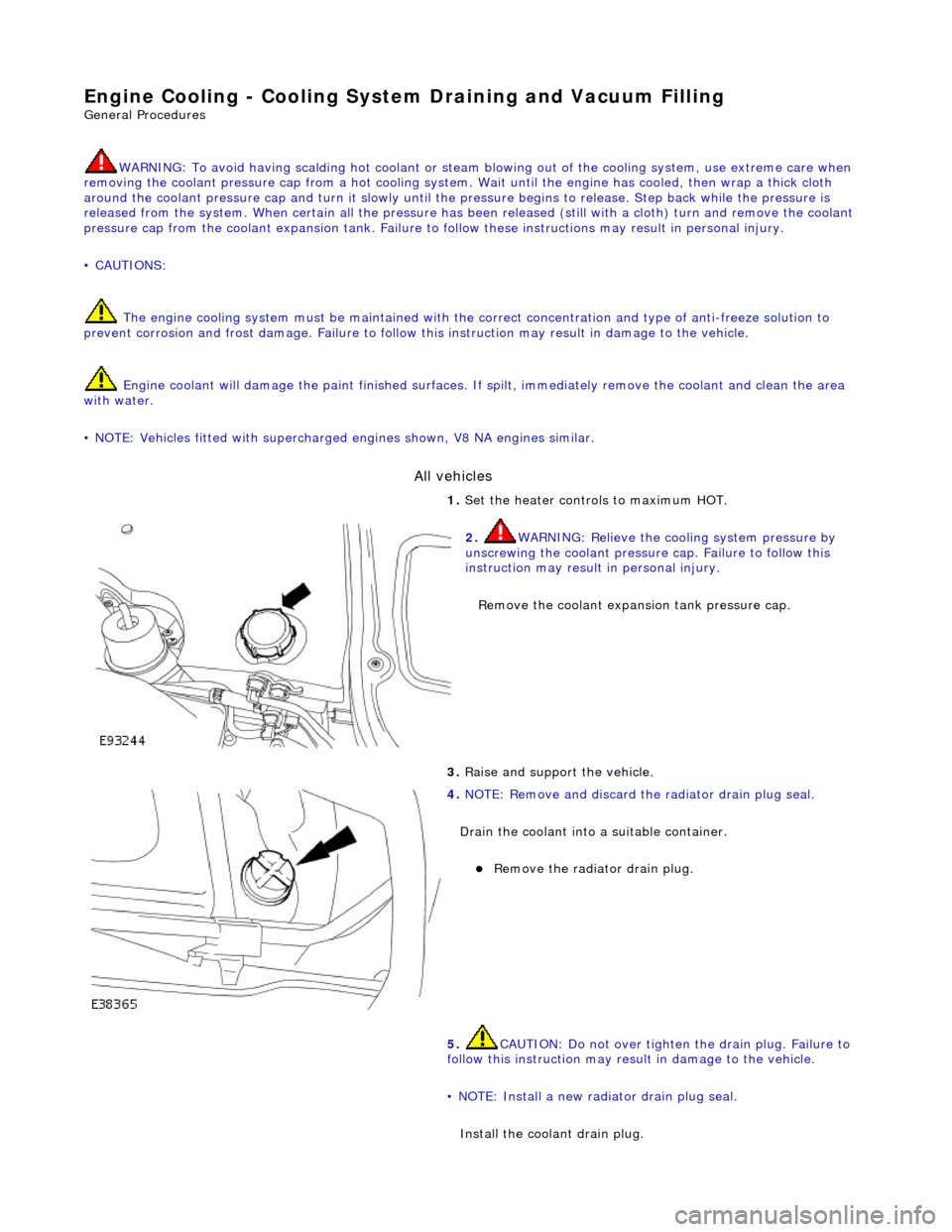
1. Set
the heater controls to maximum HOT.
2. WARN
ING: Relieve the cooling system pressure by
unscrewing the coolant pressure cap. Failure to follow this
instruction may result in personal injury.
Remove the coolant expans ion tank pressure cap.
3. Raise a
nd support the vehicle.
4. NOTE : Remov
e and discard the
radiator drain plug seal.
Drain the coolant into a suitable container.
Remove the radiato
r drain plug.
5. CAUTION: Do not over tighten the drain plug. Failure to
follow this instruction may result in damage to the vehicle.
• NOTE: Install a new radiator drain plug seal.
Install the coolant drain plug.
Page 959 of 2490
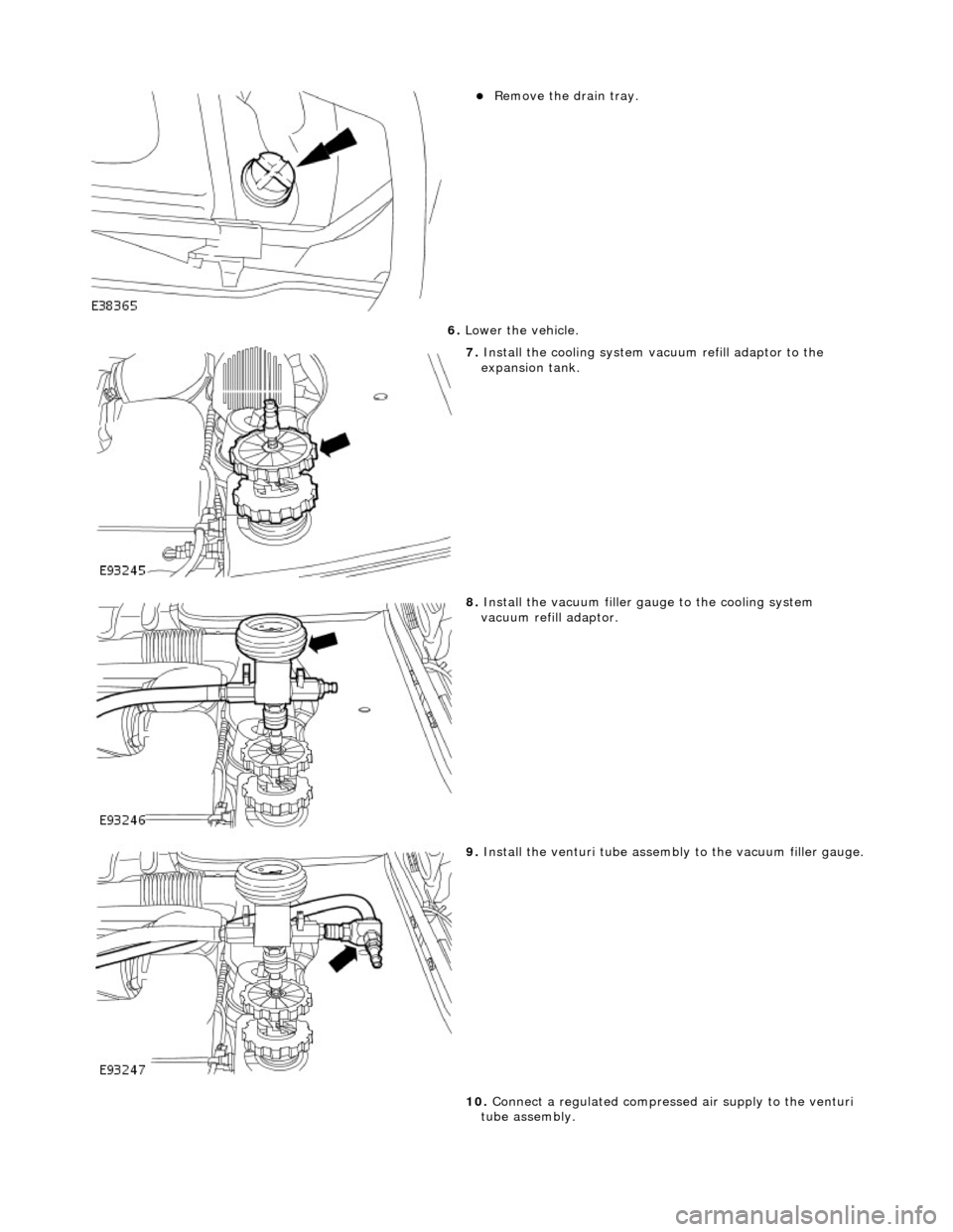
R
emove the drain tray.
6. Lower the vehicle.
7. Inst
all the cooling system va
cuum refill adaptor to the
expansion tank.
8. Inst
all the vacuum filler gauge to the cooling system
vacuum refill adaptor.
9. Inst
all the venturi tube assembly to the vacuum filler gauge.
10. Connect a regulated compressed air supply to the venturi
tube assembly.
Page 961 of 2490
Vehic
les with supercharger
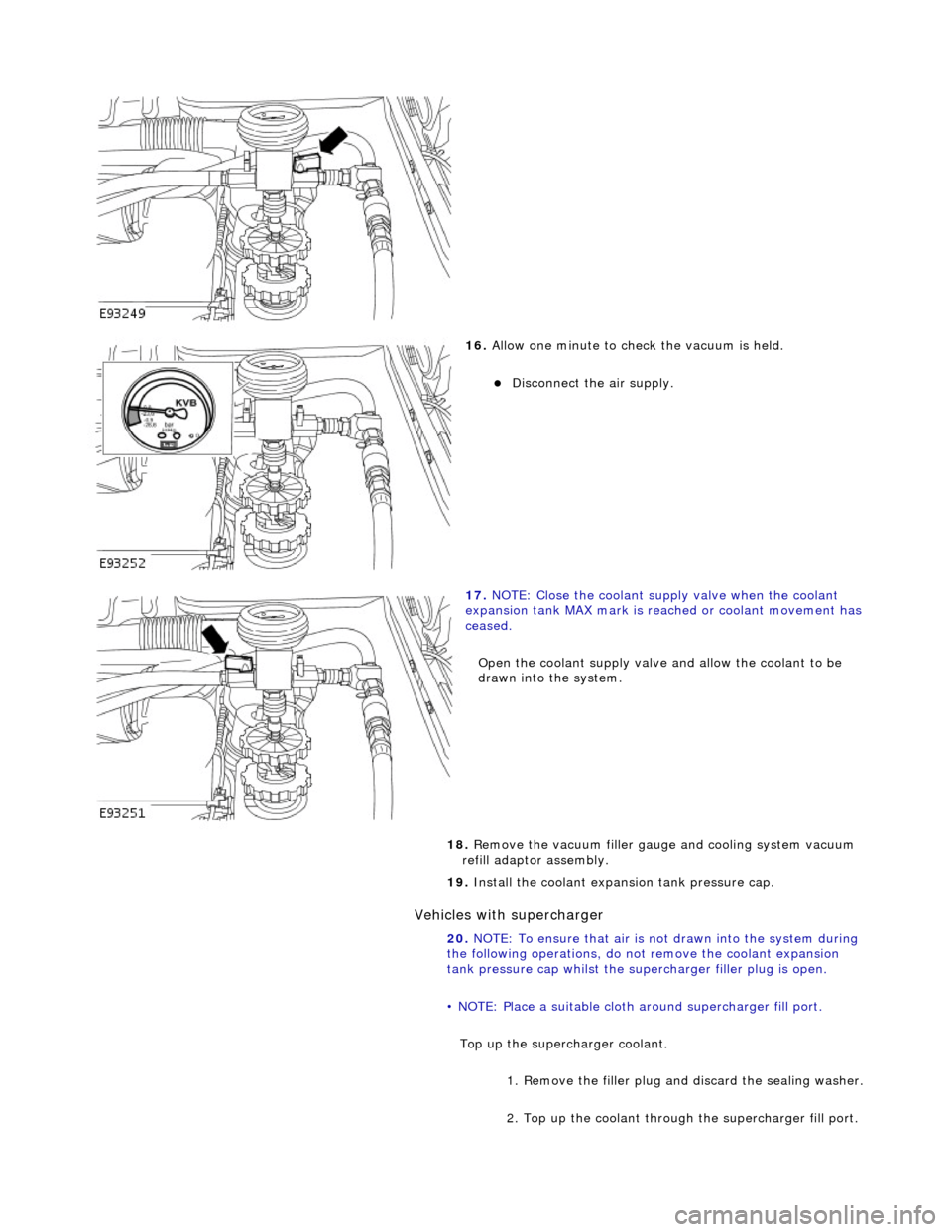
16
.
Allow one minute to check the vacuum is held.
Di
sconnect the air supply.
17
.
NOTE: Close the coolant supply valve when the coolant
expansion tank MAX mark is reached or coolant movement has
ceased.
Open the coolant supply valve and allow the coolant to be
drawn into the system.
18. Remove the vacuum filler gaug e and cooling system vacuum
refill adaptor assembly.
19. Install the coolant expansion tank pressure cap.
20. NOTE: To ensure that air is not drawn into the system during
the following operations, do not remove the coolant expansion
tank pressure cap whilst the supe rcharger filler plug is open.
• NOTE: Place a suitable cloth ar ound supercharger fill port.
Top up the superc harger coolant.
1. Remove the filler plug an d discard the sealing washer.
2. Top up the coolant through the supercharger fill port.
Page 962 of 2490
All vehicles
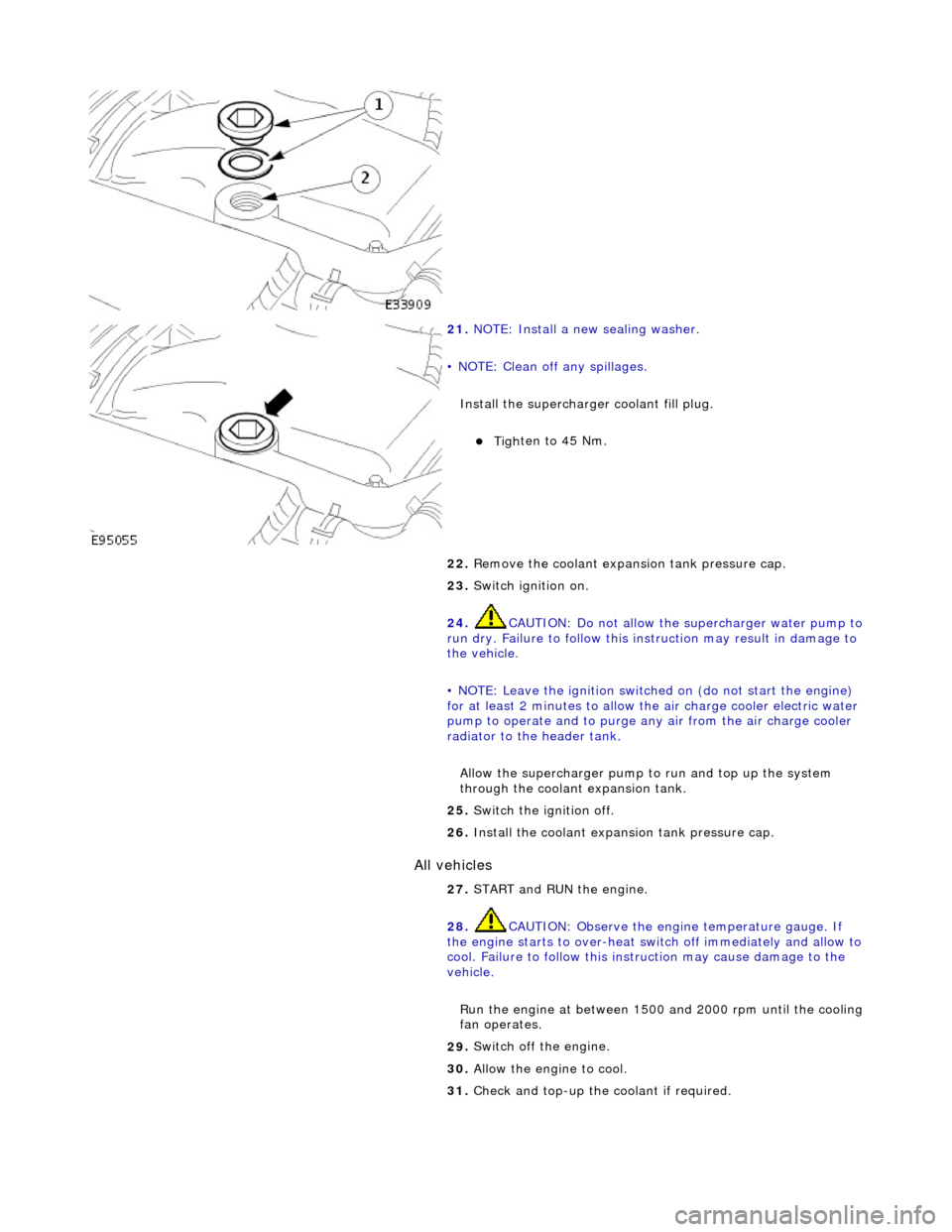
21.
N
OTE: Install a new sealing washer.
• NOTE: Clean off any spillages.
Install the supercharger coolant fill plug.
Tighte
n to 45 Nm.
22. Remove the coolant expans ion tank pressure cap.
23. Switch ignition on.
24. CAUTION: Do not allow the supercharger water pump to
run dry. Failure to follow this instruction may result in damage to
the vehicle.
• NOTE: Leave the ignition switched on (do not start the engine)
for at least 2 minutes to allow the air charge cooler electric water
pump to operate and to purge an y air from the air charge cooler
radiator to the header tank.
Allow the supercharger pump to run and top up the system
through the coolant expansion tank.
25 . Swit
ch the ignition off.
26. Install the coolant expansion tank pressure cap.
27. START and RUN the engine.
28. CAUTION: Observe the engine temperature gauge. If
the engine starts to over-heat switch off immediately and allow to
cool. Failure to follow this inst ruction may cause damage to the
vehicle.
Run the engine at between 1500 and 2000 rpm until the cooling
fan operates.
29 .
Swi
tch off the engine.
30. Allow the engine to cool.
31. Check and top-up the coolant if required.
Page 963 of 2490

Engine Cooling - Coolant Expansi
on Tank
Re
moval and Installation
Remov
al
1.
O
pen the engine compartment and fit paintwork protection
sheets.
2. R
emove the centre trim panel
from the engine compartment.
1. Remove the left hand side enclosure panel.
2. Remove the centre trim panel.
3. Ensure that the cooling system is cool and very carefully,
remove the pressure cap.
4. Place a cloth under the expansion tank to absorb any spillage
caused by disconnecting the hoses.
5. R
elease the hoses (Quick Fit connections) from the expansion
tank.
1. Release the hose, expansion tank to thermostat housing (coolant outlet pipe on supercharged
engines).
2. Release the hose, expansion tank to recovery tank.
3. Release the hose, expansion tank to radiator..
6. Fit blanking plugs to the pipes and the tank.
7. Re
move the expansion tank from the mounting.
1. Disconnect the coolant level sensor connector.
2. Remove the nuts which secures the tank.
8. Remove the expansion tank from the vehicle.
1. Use a pipe clamp to clam p the bottom hose branch.
2. Release the pipe clip an d move it along the pipe.
3. Disconnect the tank from the bottom hose and
Page 964 of 2490

In
stallation
re
move it from the vehicle.
9. Empty any surplus coolant from the expansion tank into a
drain tray.
10. Remove the cloth from the engine and clean any spillage from
the engine bay.
11 . R
emove the coolant level sensor
by carefully levering it
downwards at one side.
1. Installation is th e reverse of the re moval procedure.
Page 972 of 2490

Engine Cooling - Engine Coolant Level Switch
Remo
val and Installation
Remov
a
l
Installation
1.
Op
en the engine compartment and fit paintwork protection
sheets.
2. Remove the expansion tank; refe r to Operation (26.15.01.) in
this section.
3. Re
move the coolant level probe.
1. Use a lever to release the probe from the expansion tank and remove it.
4. Clean the expansion tank probe aperture.
1. Installation is th e reverse of the re moval procedure.
Page 973 of 2490
Engine Cooling - Radiator4.0L NA V8 - AJ27/3.2L NA V8 - AJ26
Re
moval and Installation
Remov
al
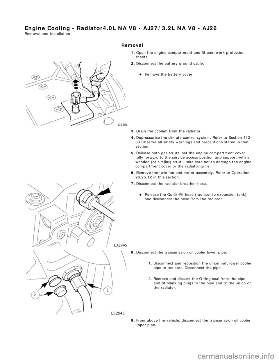
1.
O
pen the engine compartment and fit paintwork protection
sheets.
2. Di
sconnect the batt
ery ground cable.
R
emove the battery cover.
3. Drain the coolant from the radiator.
4. Depressurise the climate control system. Refer to Section 412-
03 Observe all safety warnings and precautions stated in that
section.
5. Release both gas struts, set the engine compartment cover
fully forward to the service acce ss position and support with a
wooden (or similar) strut - take care not to damage the engine
compartment cover or the radiator grille.
6. Remove the twin fan and motor assembly. Refer to Operation
26.25.12 in this section.
7. D
isconnect the radiator breather hose.
R
elease the Quick-Fit hose (radiator to expansion tank)
and disconnect the hose from the radiator.
8. Di
sconnect the transmission oil cooler lower pipe.
1. Disconnect and reposition the union nut, lower cooler pipe to radiator. Di sconnect the pipe.
2. Remove and discard the O- ring seal from the pipe
and fit blanking plugs to the pipe and to the union on
the radiator.
9. From above the vehicle, disconne ct the transmission oil cooler
upper pipe.
Page 977 of 2490
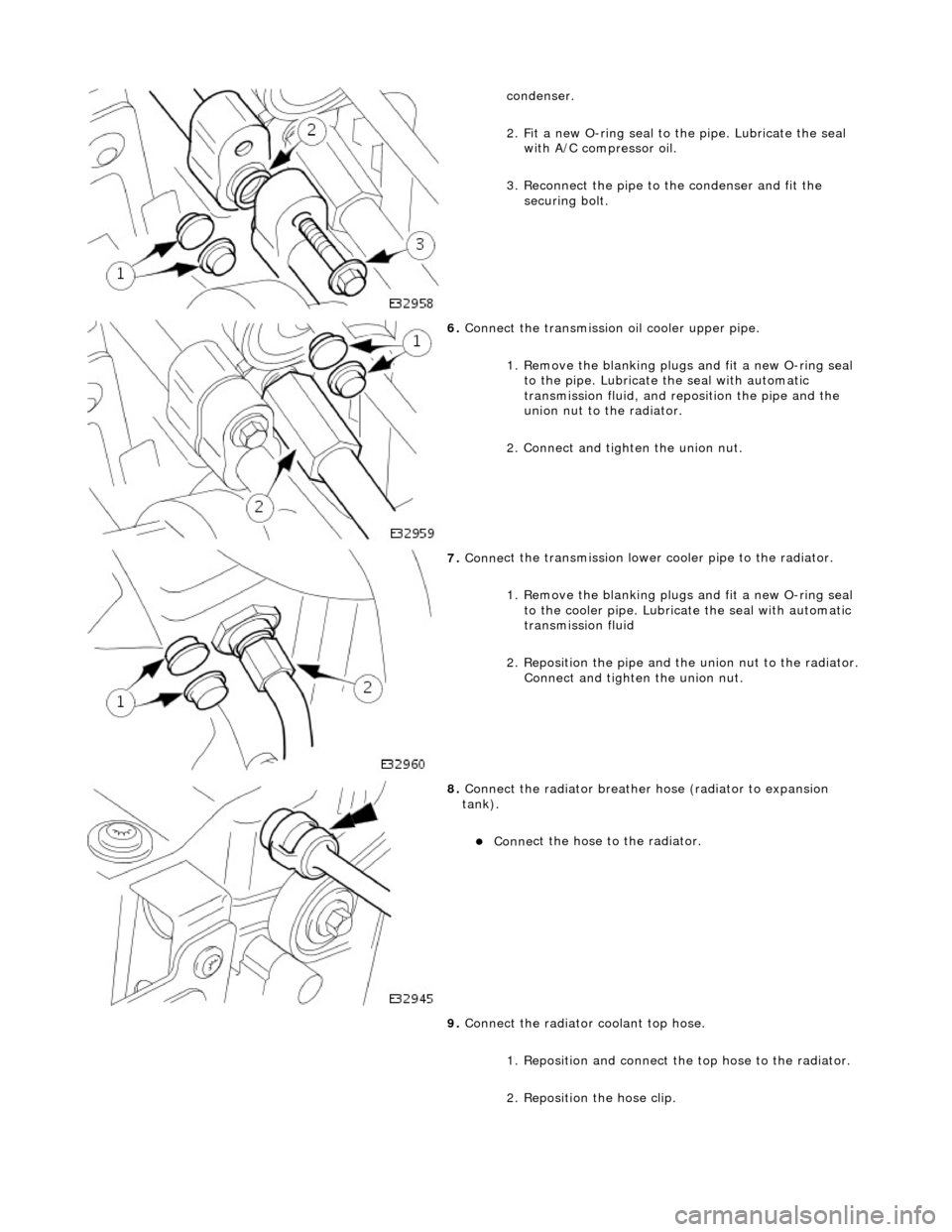
conde
nser.
2. Fit a new O-ring seal to the pipe. Lubricate the seal with A/C compressor oil.
3. Reconnect the pipe to the condenser and fit the securing bolt.
6. Conne
ct the transmission
oil cooler upper pipe.
1. Remove the blanking plugs and fit a new O-ring seal to the pipe. Lubricate the seal with automatic
transmission fluid, and re position the pipe and the
union nut to the radiator.
2. Connect and tighten the union nut.
7. Conne
ct the transmission lower cooler pipe to the radiator.
1. Remove the blanking plugs and fit a new O-ring seal to the cooler pipe. Lubricate the seal with automatic
transmission fluid
2. Reposition the pipe and th e union nut to the radiator.
Connect and tighten the union nut.
8. Connect
the radiator breather
hose (radiator to expansion
tank).
Conne
ct the hose to the radiator.
9. Connect the radiator coolant top hose.
1. Reposition and connect the top hose to the radiator.
2. Reposition the hose clip.
Page 980 of 2490
Engine Cooling - Radiator4.0L SC V8 - AJ26
Remo
val and Installation
Remov
a
l
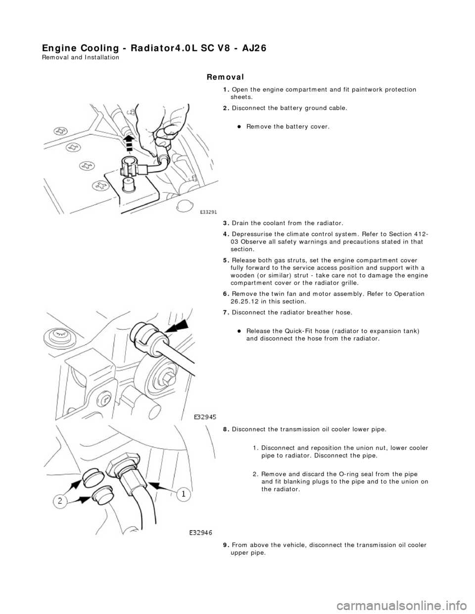
1.
Op
en the engine compartment and fit paintwork protection
sheets.
2. Disc
onnect the batt
ery ground cable.
Re
move the battery cover.
3. Drain the coolant from the radiator.
4. Depressurise the climate control system. Refer to Section 412-
03 Observe all safety warnings and precautions stated in that
section.
5. Release both gas struts, set the engine compartment cover
fully forward to the service acce ss position and support with a
wooden (or similar) strut - take care not to damage the engine
compartment cover or the radiator grille.
6. Remove the twin fan and motor assembly. Refer to Operation
26.25.12 in this section.
7. Di
sconnect the radiator breather hose.
R
e
lease the Quick-Fit hose (radiator to expansion tank)
and disconnect the hose from the radiator.
8. Disc
onnect the transmission oil cooler lower pipe.
1. Disconnect and reposition the union nut, lower cooler pipe to radiator. Di sconnect the pipe.
2. Remove and discard the O- ring seal from the pipe
and fit blanking plugs to the pipe and to the union on
the radiator.
9. From above the vehicle, disconne ct the transmission oil cooler
upper pipe.