tank JAGUAR X308 1998 2.G User Guide
[x] Cancel search | Manufacturer: JAGUAR, Model Year: 1998, Model line: X308, Model: JAGUAR X308 1998 2.GPages: 2490, PDF Size: 69.81 MB
Page 921 of 2490
2
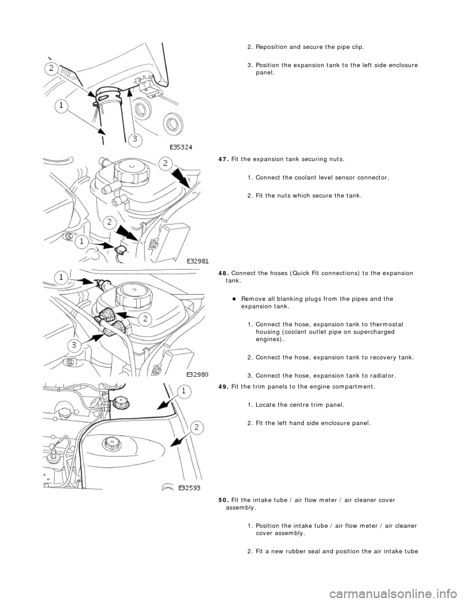
. Reposition and secure the pipe clip.
3. Position the expansion tank to the left side enclosure
panel.
47
.
Fit the expansion tank securing nuts.
1. Connect the coolant level sensor connector.
2. Fit the nuts which secure the tank.
48
.
Connect the hoses (Quick Fit connections) to the expansion
tank.
Remove all blanking plug s
from the pipes and the
expansion tank.
1. Connect the hose, expansion tank to thermostat housing (coolant outlet pipe on supercharged
engines).
2. Connect the hose, expansion tank to recovery tank.
3. Connect the hose, expansion tank to radiator.
49
.
Fit the trim panels to the engine compartment.
1. Locate the centre trim panel.
2. Fit the left hand side enclosure panel.
50. Fit the intake tube / air flow meter / air cleaner cover
assembly.
1. Position the intake tube / air flow meter / air cleaner
cover assembly.
2. Fit a new rubber seal and po sition the air intake tube
Page 924 of 2490
Engine Cooling
- Engine Cooling
Descr
i
ption and Operation
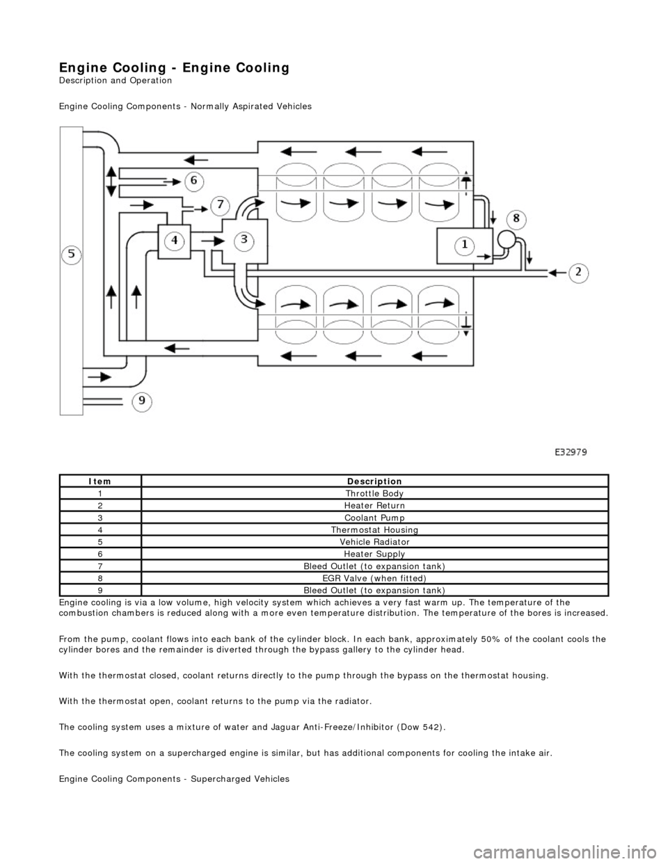
Engine Cooling Comp onents - Normally Aspirated Vehicles
Engine cooling is via a low volume, high velocity system which achieves a very fast warm up. The temperature of the
combustion chambers is reduced along with a more even temperature distribution. The temperature of the bores is increased.
F r
om the pump, coolant flows into each bank of the cylinder bl
ock. In each bank, approximately 50% of the coolant cools the
cylinder bores and the remainder is diverted th rough the bypass gallery to the cylinder head.
With the thermostat closed, coolant returns directly to the pump through the bypass on the thermostat housing.
With the thermostat open, coolant returns to the pump via the radiator.
The cooling system uses a mixture of water and Jaguar Anti-Freeze/Inhibitor (Dow 542).
The cooling system on a supercharged engine is similar, but has additional components for cooling the intake air.
Engine Cooling Co mponents - Supercharged Vehicles
ItemDescrip
tion
1Thr
ottle B
ody
2Hea
ter Return
3Coolant Pum p
4Ther
mostat Housing
5Vehicle Radia
t
or
6Hea
ter Su
pply
7Bleed
Outl
et (to expansion tank)
8EGR V
a
lve (when fitted)
9Bleed
Outl
et (to expansion tank)
Page 925 of 2490
T
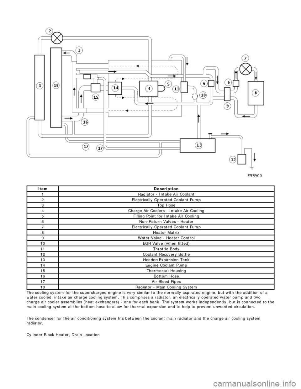
he cooling system for the supercharged engine is very similar
to the normally aspirated engine, but with the addition of a
water cooled, intake air charge cooling system. This comprises a radiator, an electrically operated water pump and two
charge air cooler assemblies (heat exchangers) - one for each bank. The system works independently, but is connected to the
main cooling system at the bottom hose to allow for therma l expansion and to help to prevent unwanted circulation.
The condenser for the air conditioning system fits between th e coolant main radiator and the charge air cooling system
radiator.
Cylinder Block Heater, Drain Location
ItemDe
scription
1Rad
iator - Intake Air Coolant
2Ele
ctrically Operated Coolant Pump
3Top Hose
4Charge Air Coo
lers -
Intake Air Cooling
5Fi
lling Point for Intake Air Cooling
6N
on-Return Valves - Heater
7Ele
ctrically Operated Coolant Pump
8Hea
ter Matrix
9Wate
r Valve - Heater Control
10EGR V
alve (when fitted)
11Thr
ottle Body
12Coolan
t Recovery Bottle
13H
eader/Expansion Tank
14Eng
ine Coolant Pump
15The
rmostat Housing
16Bottom
Hose
17Air Bleed
Pipes
18Rad
iator - Main Cooling System
Page 929 of 2490

The cooling
pack incorporates the radiator a
ssembly with integral transmission oil cool er (located in the radiator outlet tank),
an air conditioning condenser, and the cooling fans and cowl assembly.
The cooling pack on supercharged vehicles is the same as described above, but with the addition of a charge air cooler
coolant radiator located in front of the condenser.
Radiator Mounti
ng/Retention
T
he radiator is mounted on four rubber mounts, one on each
end of the upper and lower horizontal face. The two lower
mountings are supported on two isolated brackets mounted on the body; the lower cradle assembly has subsequently been
deleted.
A closing panel made from polypropylene, which retains the radiat or assembly, fits over the top of the radiator and is bolted
to the vehicle top panel.
Coolant Hoses - Engine
Page 930 of 2490
Whe r
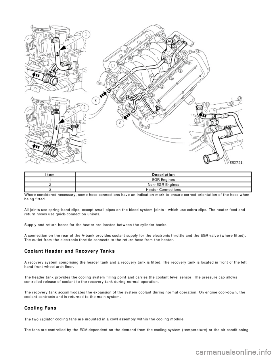
e considered necessary, some hose conn
ections have an indication mark to ensure correct orientation of the hose when
being fitted.
All joints use spring-band clips, except small pipes on the bleed system joints - which use cobra clips. The heater feed and
return hoses use quick-connection unions.
Supply and return hoses for the heater are located between the cylinder banks.
A connection on the rear of the A-bank provides coolant supply for the electronic throttle and the EGR valve (where fitted).
The outlet from the electronic throttle connects to the return hose from the heater.
Cool
ant Header and Recovery Tanks
A recovery system comp
rising the header tank
and a recovery tank is fitted. The recove ry tank is located in front of the left
hand front wheel arch liner.
The header tank provides the cooling system filling point and carries the coolant level sensor. The pressure cap allows
controlled release of coolant to the re covery tank during normal operation.
The recovery tank accommodates the expansion of the system coolant during normal operation. On engine cool-down, the
coolant contracts and is returned to the main system.
Coo lin
g Fans
The two
rad
iator cooling fans are mounted in
a cowl assembly within the cooling module.
The fans are controlled by the ECM dependent on the demand fr om the cooling system (temperature) or the air conditioning
ItemDescrip
tion
1EGR
E
ngines
2Non
-
EGR Engines
3Hea
ter Connections
Page 953 of 2490
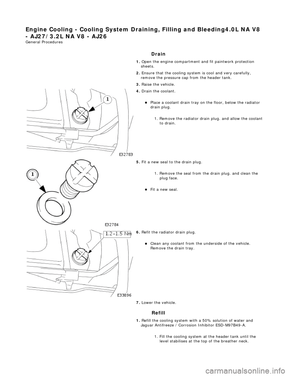
Engine Cooling - Cooling System Draining,
Filling and Bleeding4.0L NA V8
- AJ27/3.2L NA V8 - AJ26
Gen
eral Procedures
Drain
Refill
1. O
pen the engine compartment and fit paintwork protection
sheets.
2. Ensure that the cooling system is cool and very carefully,
remove the pressure cap from the header tank.
3. Raise the vehicle.
4. Drain th
e coolant.
Pla
ce a coolant drain tray on
the floor, below the radiator
drain plug.
1. Remove the radiator drain plug. and allow the coolant to drain.
5. Fit a new seal to the
drain plug.
1. Remove the seal from the drain plug. and clean the plug face.
Fit a new seal.
6. Re
fit the radiator drain plug.
Cl
ean any coolant from the
underside of the vehicle.
Remove the drain tray.
7. Lower the vehicle.
1. Refill the cooling system with a 50% solution of water and
Jaguar Antifreeze / Corrosion Inhibitor ESD-M97B49-A.
1. Fill the cooling system at the header tank until the level stabilises at the top of the breather neck.
Page 954 of 2490
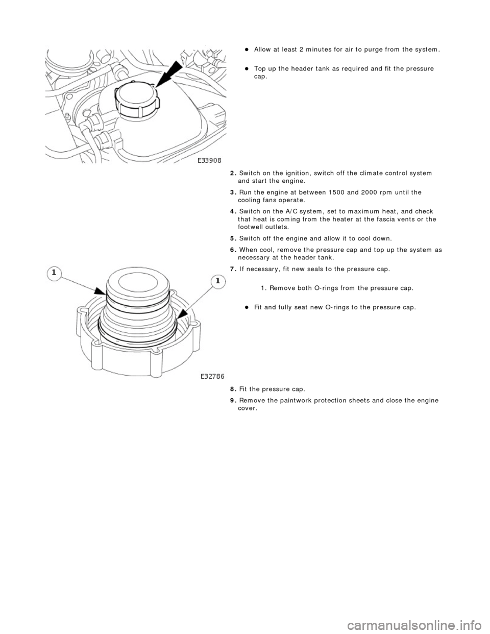
Allow at least 2 minutes f
or ai
r to purge from the system.
Top up the he
ader tank as re
quired and fit the pressure
cap.
2. Switch on the ignition, switch off the climate control system
and start the engine.
3. Run the engine at between 1500 and 2000 rpm until the
cooling fans operate.
4. Switch on the A/C system, set to maximum heat, and check
that heat is coming from the heat er at the fascia vents or the
footwell outlets.
5. Switch off the engine and allow it to cool down.
6. When cool, remove the pressure cap and top up the system as
necessary at the header tank.
7. If n e
cessary, fit new seals to the pressure cap.
1. Remove both O-rings from the pressure cap.
Fit and
fully seat new O-rings to the pressure cap.
8. Fit the pressure cap.
9. Remove the paintwork protection sheets and close the engine
cover.
Page 955 of 2490
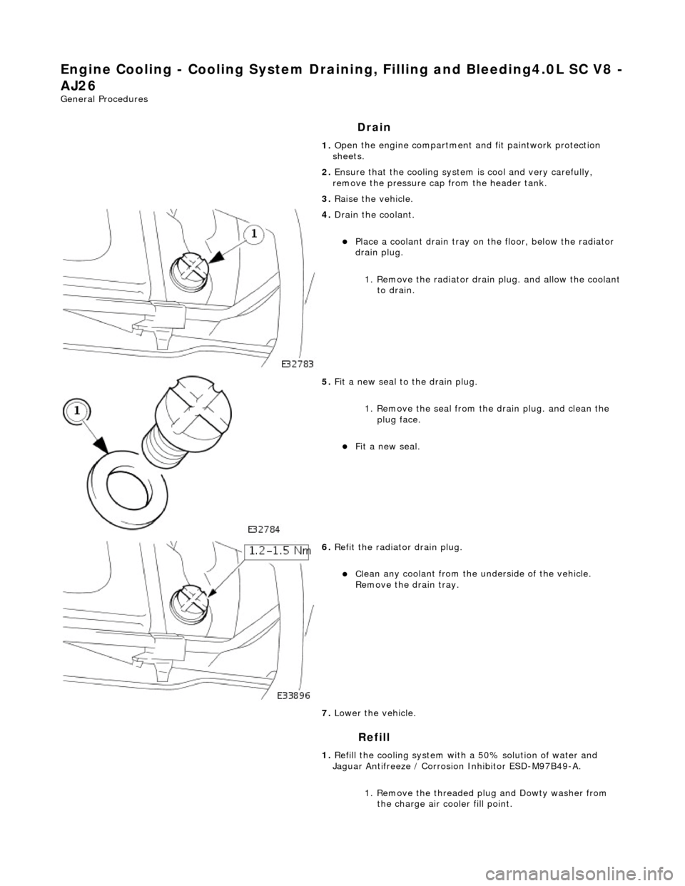
Engine Cooling - Cooling System Draining, Filling and Bleeding4.0L SC V8 -
AJ26
Gen
eral Procedures
Drain
Refill
1. O
pen the engine compartment and fit paintwork protection
sheets.
2. Ensure that the cooling system is cool and very carefully,
remove the pressure cap from the header tank.
3. Raise the vehicle.
4. Drain th
e coolant.
Pla
ce a coolant drain tray on
the floor, below the radiator
drain plug.
1. Remove the radiator drain plug. and allow the coolant to drain.
5. Fit a new seal to the
drain plug.
1. Remove the seal from the drain plug. and clean the plug face.
Fit a new seal.
6. Re
fit the radiator drain plug.
Cl
ean any coolant from the
underside of the vehicle.
Remove the drain tray.
7. Lower the vehicle.
1. Refill the cooling system with a 50% solution of water and
Jaguar Antifreeze / Corrosion Inhibitor ESD-M97B49-A.
1. Remove the threaded plug and Dowty washer from the charge air cooler fill point.
Page 956 of 2490
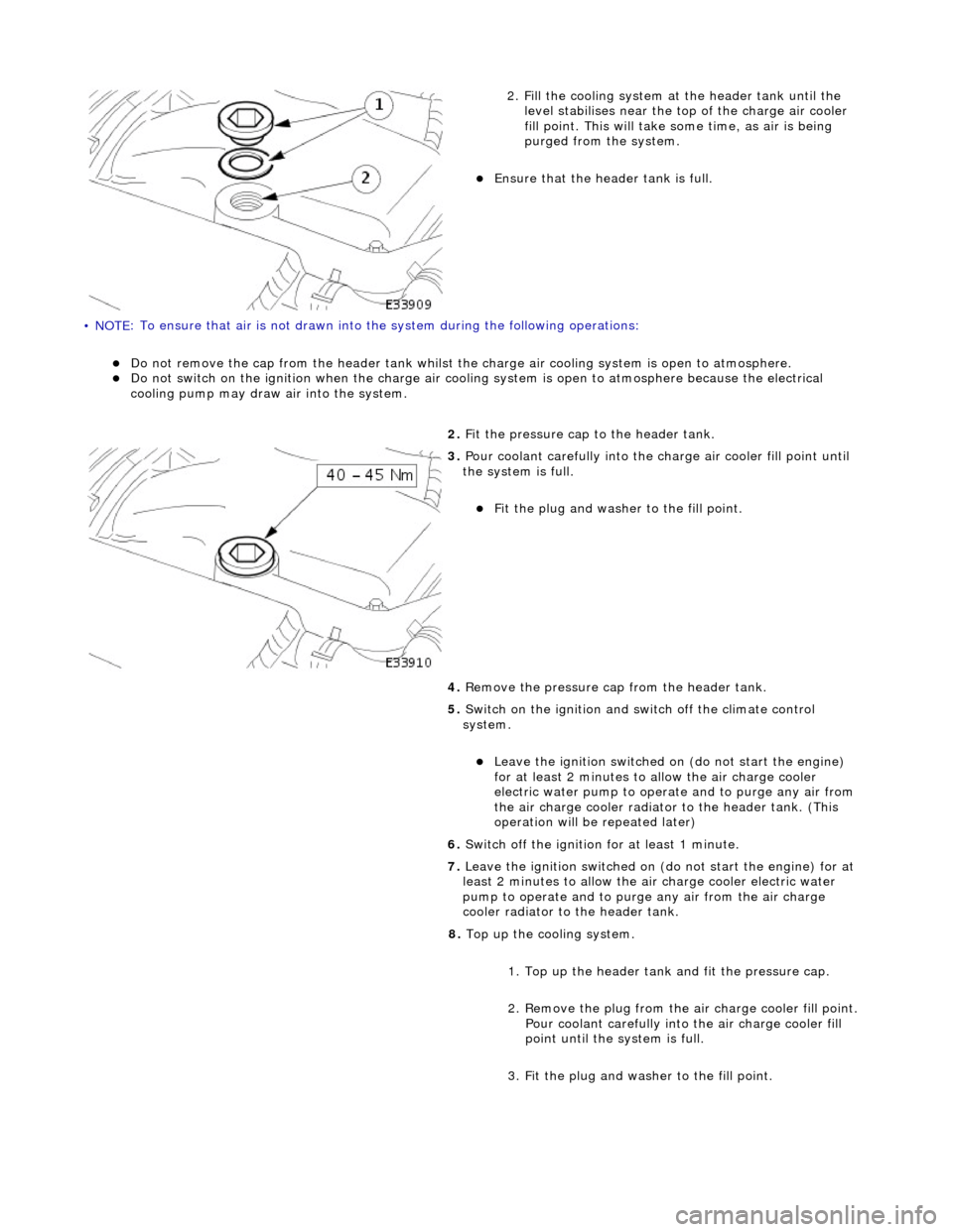
• NOTE
: To ensure that
air is not drawn into the system during the following operations:
Do
not remove the cap from the header tank whilst the
charge air cooling system is open to atmosphere.
Do
not switch on the ignition when th
e charge air cooling system is open to atmosphere because the electrical
cooling pump may draw air into the system.
2. Fi
ll the cooling system at the header tank until the
level stabilises near the to p of the charge air cooler
fill point. This will take some time, as air is being
purged from the system.
Ensure that the head
er tank is full.
2. Fit the pressure cap to the header tank.
3. Pour coolant careful l
y into the charge air cooler fill point until
the system is full.
Fi t t
he plug and washer to the fill point.
4. Remove the pressure cap from the header tank.
5. Switch on the ignition and switch off the climate control
system.
Le ave
the ignition switched on (do not start the engine)
for at least 2 minutes to allow the air charge cooler
electric water pump to oper ate and to purge any air from
the air charge cooler radiator to the header tank. (This
operation will be repeated later)
6. Switch off the ignition for at least 1 minute.
7. Leave the ignition switched on (do not start the engine) for at
least 2 minutes to allow the air charge cooler electric water
pump to operate and to purg e any air from the air charge
cooler radiator to the header tank.
8. Top up the cooling system.
1. Top up the header tank and fit the pressure cap.
2. Remove the plug from the air charge cooler fill point. Pour coolant carefully into the air charge cooler fill
point until the system is full.
3. Fit the plug and washer to the fill point.
Page 957 of 2490
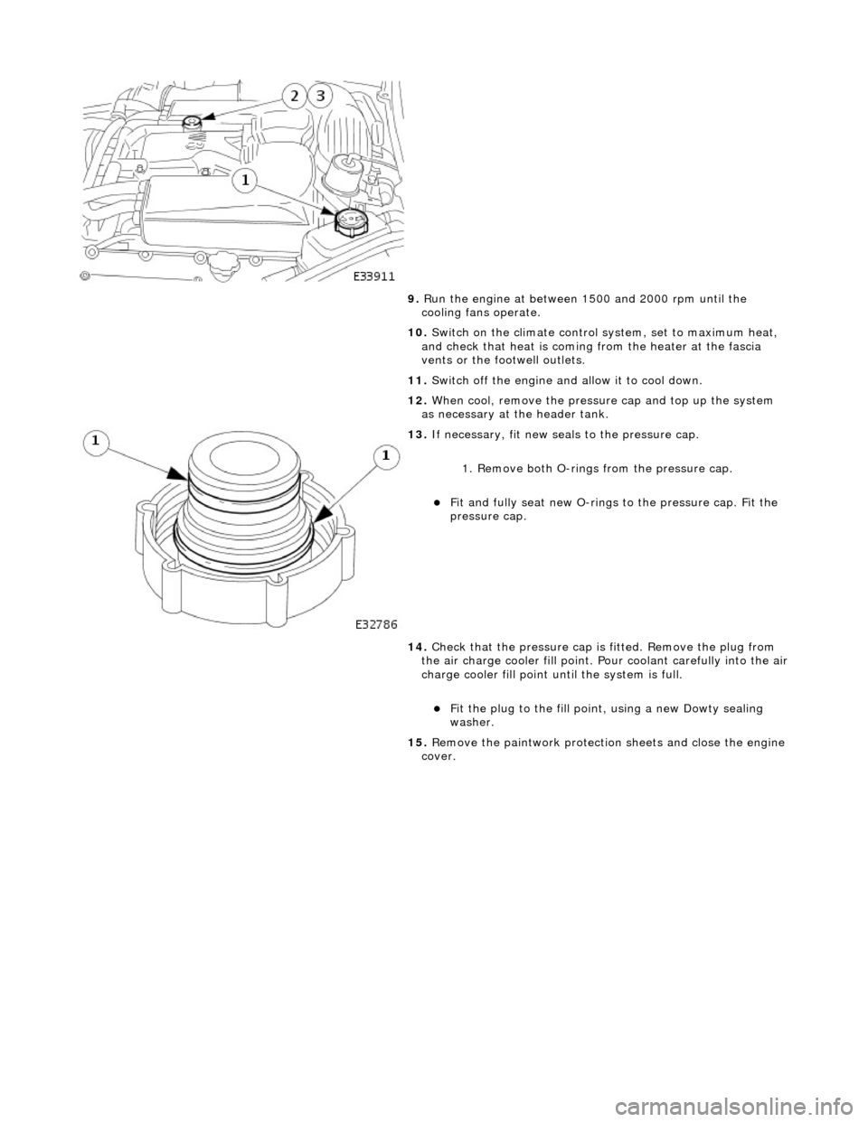
9.
R
un the engine at between 1500 and 2000 rpm until the
cooling fans operate.
10. Switch on the climate control system, set to maximum heat,
and check that heat is coming from the heater at the fascia
vents or the footwell outlets.
11. Switch off the engine and allow it to cool down.
12. When cool, remove the pressure cap and top up the system
as necessary at the header tank.
13
.
If necessary, fit new seals to the pressure cap.
1. Remove both O-rings from the pressure cap.
Fit and
fully seat new O-rings
to the pressure cap. Fit the
pressure cap.
14. Check that the pressure cap is fitted. Remove the plug from
the air charge cooler fill point. Pour coolant carefully into the air
charge cooler fill point until the system is full.
F
it the plug to the fill poin
t, using a new Dowty sealing
washer.
15. Remove the paintwork protection sheets and close the engine
cover.