JAGUAR X308 1998 2.G Workshop Manual
X308 1998 2.G
JAGUAR
JAGUAR
https://www.carmanualsonline.info/img/21/7640/w960_7640-0.png
JAGUAR X308 1998 2.G Workshop Manual
Trending: parking brake, oil capacities, brake vacuum hose, P0352, wheel bolt torque, wiring diagram, 19.60.04
Page 291 of 2490
R
ear Drive Axle/Differential - Differential Output Shaft Bearing
In-v
ehicle Repair
Remov
al
S
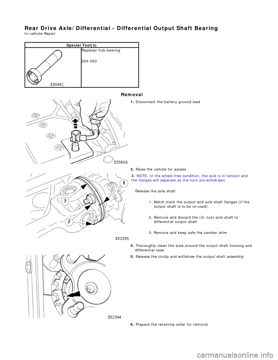
pecial Tool(s)
Replacer hu
b bearing
204-083
1. Di
sconnect the battery ground lead
2. Raise the vehicle for access
3. NO
TE: In the wheel-free condition, the axle is in tension and
the flanges will separate as the nuts are withdrawn
Release the axle shaft
1. Match mark the output an d axle shaft flanges (if the
output shaft is to be re-used)
2. Remove and discard the (4) nuts axle shaft to differential output shaft
3. Remove and keep safe the camber shim
4. T
horoughly clean the area around the output shaft housing and
differential case
5. Relea
se the circlip and withdraw the output shaft assembly
6. Prepare the retaining collar for removal
Page 292 of 2490
In
stallation
1.
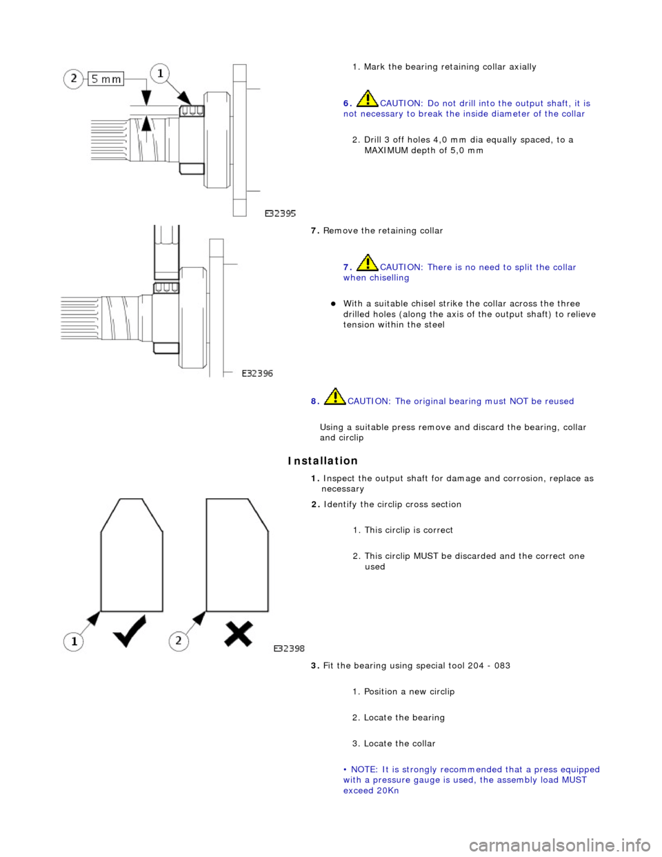
Mark the bearing retaining collar axially
6. CAUTION: Do not drill into the output shaft, it is
not necessary to break the inside diameter of the collar
2. Drill 3 off holes 4,0 mm dia equally spaced, to a MAXIMUM depth of 5,0 mm
7. Re
move the retaining collar
7. CAUTION: There is no need to split the collar
when chiselling
W i
th a suitable chisel strike
the collar across the three
drilled holes (along the axis of the output shaft) to relieve
tension within the steel
8. CAUTIO
N: The original bearing must NOT be reused
Using a suitable press remove an d discard the bearing, collar
and circlip
1. Ins
pect the output shaft for da
mage and corrosion, replace as
necessary
2. Id
entify the circlip cross section
1. This circlip is correct
2. This circlip MUST be di scarded and the correct one
used
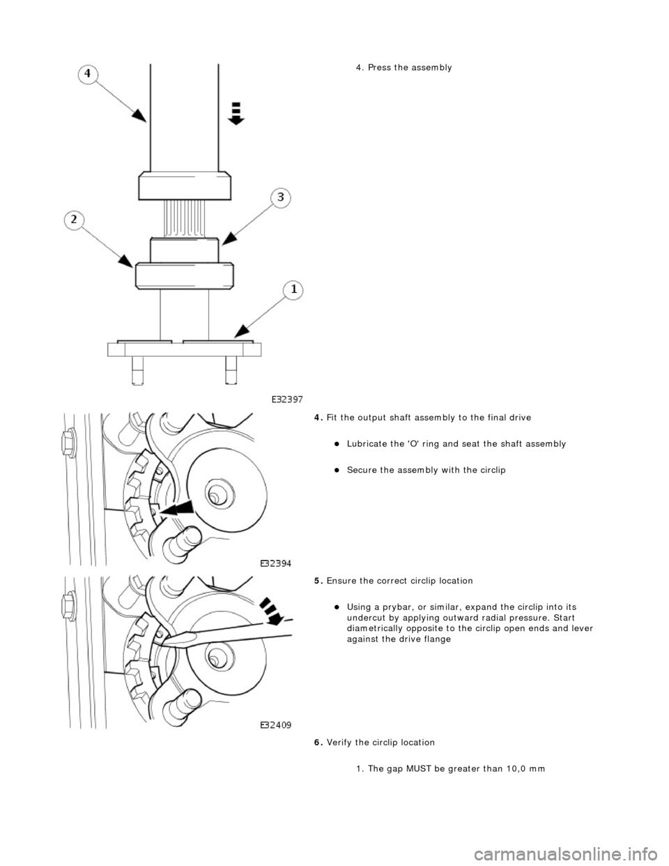
3. Fit the bearing using special tool 204 - 083
1. Position a new circlip
2. Locate the bearing
3. Locate the collar
• NOTE: It is strongly reco mmended that a press equipped
with a pressure gauge is us ed, the assembly load MUST
exceed 20Kn
Page 293 of 2490
4.
Press the assembly
4. Fi
t the output shaft assembly to the final drive
Lubri
cate the 'O' ring and
seat the shaft assembly
Secu
re the assembly with the circlip
5. Ensure the correct circli
p location
U
sing a prybar, or similar, expand the circlip into its
undercut by applying outwar d radial pressure. Start
diametrically opposite to the circlip open ends and lever
against the drive flange
6. Verify the circlip location
1. The gap MUST be greater than 10,0 mm
Page 294 of 2490
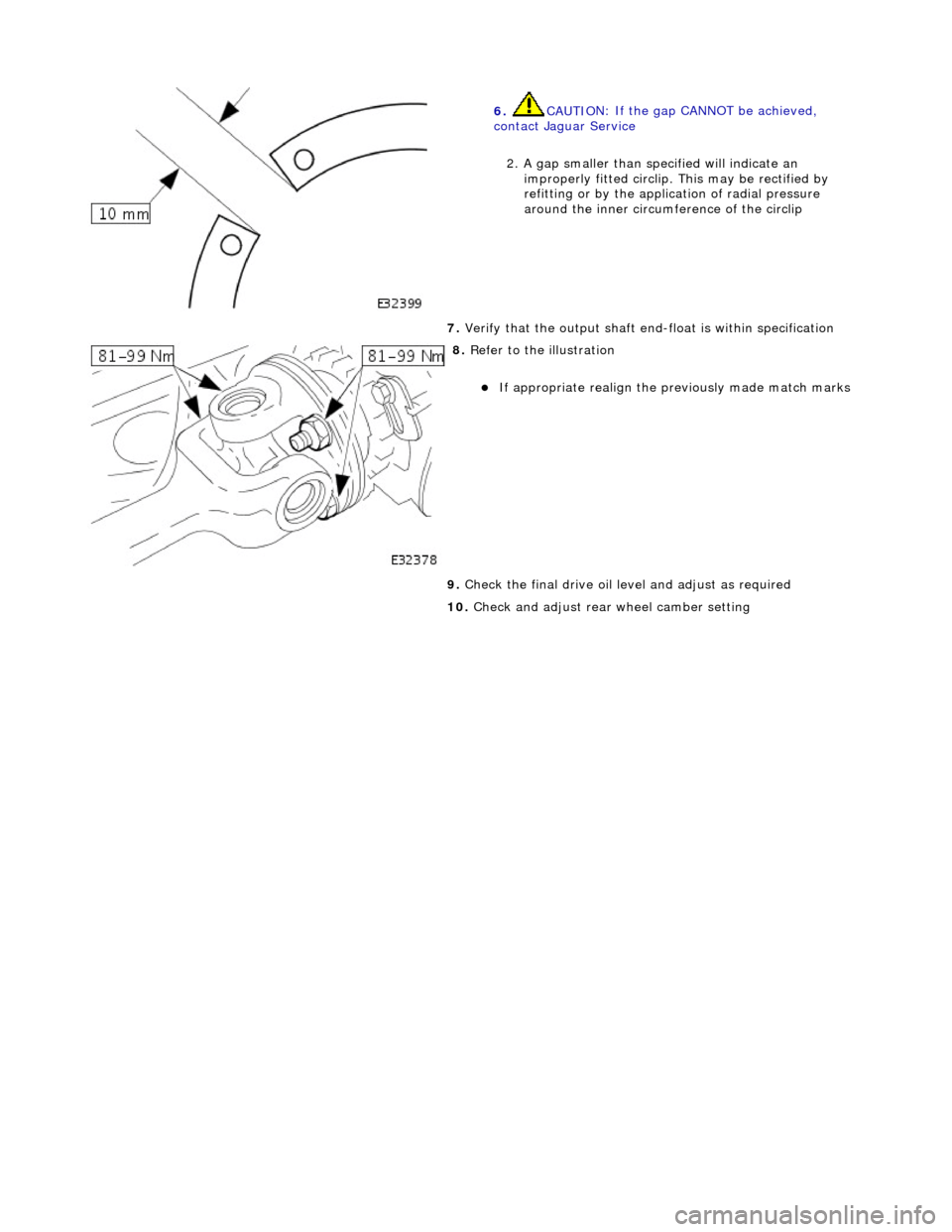
6.
CAUTIO
N: If the gap CANNOT be achieved,
contact Jaguar Service
2. A gap smaller than specified will indicate an improperly fitted circlip. This may be rectified by
refitting or by the application of radial pressure
around the inner circum ference of the circlip
7. Verify t
hat the output shaft end-float is within specification
8. Re
fer to the illustration
If
app
ropriate realign the pr
eviously made match marks
9. Check the final drive oil level and adjust as required
10. Check and adjust rear wheel camber setting
Page 295 of 2490
R
ear Drive Axle/Differential - Drive Pinion Flange and Drive Pinion Seal
In-v
ehicle Repair
Remov
al
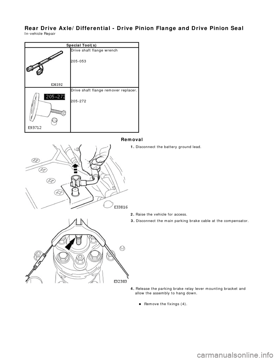
S
pecial Tool(s)
Drive sh
aft flange wrench
205-053
D
rive shaft flange remover replacer.
205-272
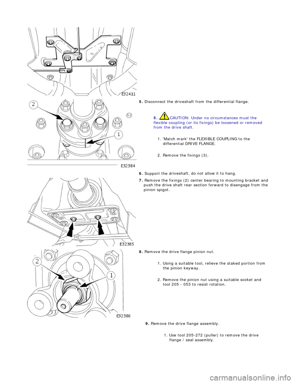
1. Di
sconnect the battery ground lead.
2. Raise the vehicle for access.
3. Disconnect the main parking br ake c
able at the compensator.
4. Release the parking brake relay lever mounting bracket and
allow the assembly to hang down.
R
emove the fixings (4).
Page 296 of 2490
5. Disconne
ct the driveshaft fr
om the differential flange.
5. CAUTION: Under no circumstances must the
flexible coupling (or its fixings) be loosened or removed
from the drive shaft.
1. 'Match mark' the FLEX IBLE COUPLING to the
differential DRIVE FLANGE.
2. Remove the fixings (3).
6. Support the d
riveshaft, do not allow it to hang.
7. Re
move the fixings (2) center
bearing to mounting bracket and
push the drive shaft rear sectio n forward to disengage from the
pinion spigot.
8. Remove the drive flange pinion nu
t.
1. Using a suitable tool, re lieve the staked portion from
the pinion keyway.
2. Remove the pinion nut using a suitable socket and tool 205 - 053 to resist rotation.
9. Remove the drive flange assembly.
1. Use tool 205-272 (puller) to remove the drive flange / seal assembly.
Page 297 of 2490
I
nstallation
10
.
Clean the seal counterbore.
1. Installation is the re verse of the removal procedure, noting the
following;
2. Lightly lubricate the seal O/D.
3. Chec
k for the correct assembly condition.
E
nsure that the seal, Ryton
ring and backing are aligned
and in contact with each other.
4. NOTE: Correct pinion seal location is automatic.
`Pull' the pinion flan ge / seal assembly down with the pinion
nut - do not hammer the flange.
5. R
efer to the illustration.
R
otate the pinion prior to final tightening.
St
ake the nut to the pinion.
6. Check the pinion drive flange axial run-out.
0,
08 mm MAX TIR.
If t
his specification is exceeded, renew the flange / seal
assembly.
Page 298 of 2490
7. Chec k
that the pinion sp
igot radial run-out.
0,08
mm MAX TIR.
If t
hi
s specification is exceeded, contact Jaguar Service.
8. Re
fer to the illustration.
R
e
new the driveshaft fixings.
9. Re
fer to the illustration.
E
n
sure that the bear
ing is central.
10. Refer to the illustration.
Page 299 of 2490
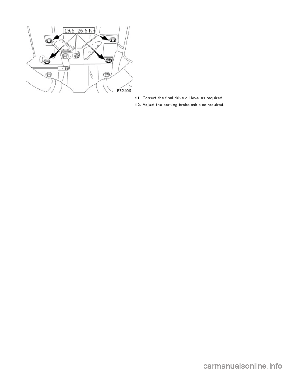
11
.
Correct the final drive oil level as required.
12. Adjust the parking brak e cable as required.
Page 300 of 2490
Rea
r Drive Axle/Differential - Axle Assembly
Re
mo
val and Installation
Remov
a
l
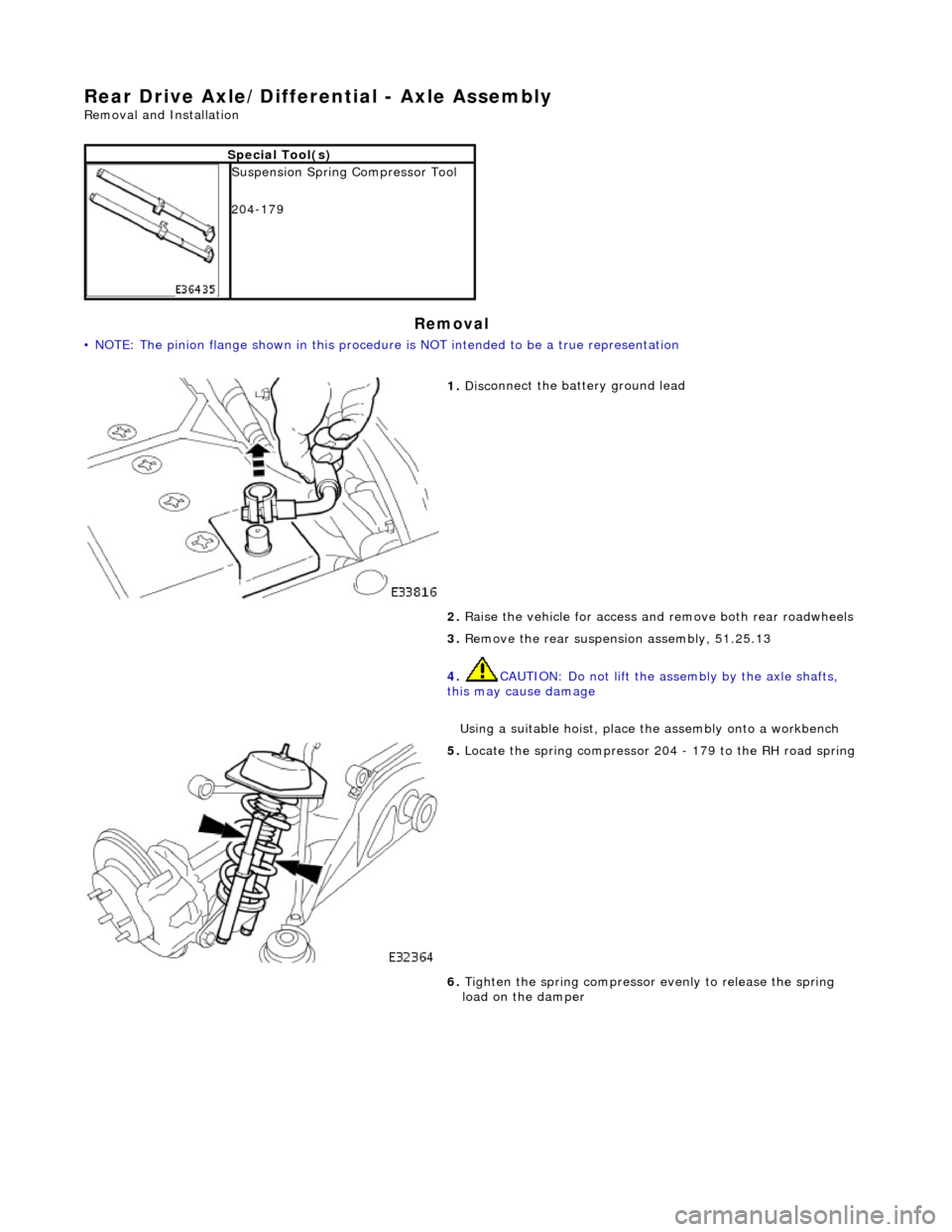
•
NOTE: The pinion flange shown in this procedure is NOT intended to be a true representation
S
p
ecial Tool(s)
Suspensi
on
Spring Compressor Tool
204-179
1. Disc
onnect the battery ground lead
2. Raise the vehicle for access and remove both rear roadwheels
3. Remove the rear suspensi on assembly, 51.25.13
4. CAUTION: Do not lift the assembly by the axle shafts,
this may cause damage
Using a suitable hoist, place the assembly onto a workbench
5. Locat e
the spring compressor 204
- 179 to the RH road spring
6. Tighten the spring compressor evenly to release the spring
load on the damper
Trending: parking brake ORDER BY 10, schematic, mirror controls, Wipes, cruise, fuel fill door release, 303-01
