JAGUAR X308 1998 2.G Workshop Manual
Manufacturer: JAGUAR, Model Year: 1998, Model line: X308, Model: JAGUAR X308 1998 2.GPages: 2490, PDF Size: 69.81 MB
Page 251 of 2490
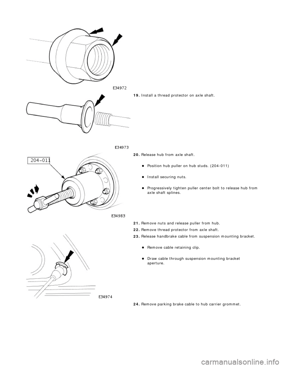
19
.
Install a thread protector on axle shaft.
20
.
Release hub from axle shaft.
Position hu
b puller on hub studs. (204-011)
Inst
all securing nuts.
Progres
sively tighten
puller center bolt to release hub from
axle shaft splines.
21. Remove nuts and release puller from hub.
22. Remove thread protec tor from axle shaft.
23
.
Release handbrake cable from suspension mounting bracket.
Remove cable reta
ining clip.
Draw c
able through suspension mounting bracket
aperture.
24. Remove parking brake cable to hub carrier grommet.
Page 252 of 2490
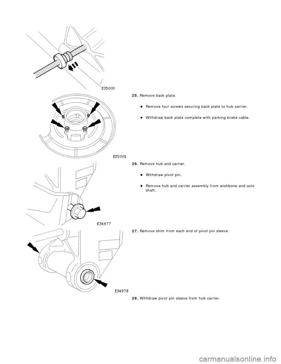
25. Remove back plate.
Re
move four screws securing
back plate to hub carrier.
Withdraw back plate
complete
with parking brake cable.
26 . Remove h
ub and carrier.
With
draw pivot pin
.
R
e
move hub and carrier assemb
ly from wishbone and axle
shaft.
27 . R
emove shim from each end of pivot pin sleeve.
28. Withdraw pivot pin sleeve from hub carrier.
Page 253 of 2490
I
nstallation
29
.
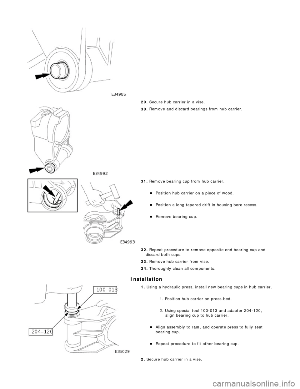
Secure hub carrier in a vise.
30
.
Remove and discard bear ings from hub carrier.
31
.
Remove bearing cup from hub carrier.
Posit
ion hub carrier on a piece of wood.
Position a lo
ng tapered drif
t in housing bore recess.
Remove bearin
g cup.
32. Repeat procedure to remove opposite end bearing cup and
discard both cups.
33. Remove hub carrier from vise.
34. Thoroughly clean all components.
1. Using a h
ydraulic press, install
new bearing cups in hub carrier.
1
. Position hub carri
er on press-bed.
2. Using special tool 100-013 and adapter 204-120, align bearing cup to hub carrier.
Al
ign assembly to ram, and
operate press to fully seat
bearing cup.
Repeat
procedure to fi
t other bearing cup.
2. Secure hub carri er in a vise.
Page 254 of 2490
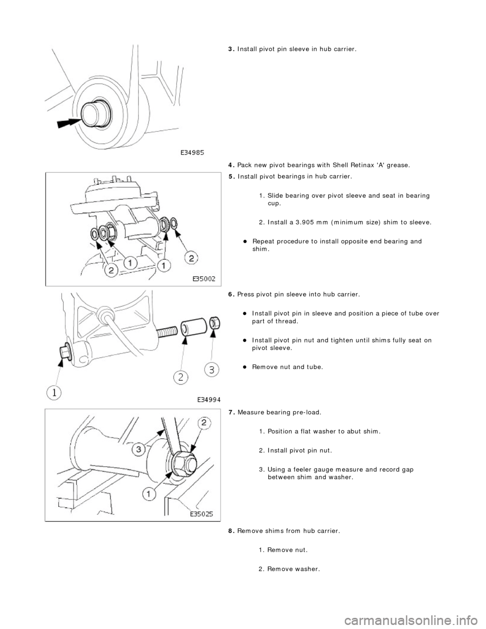
3. Install pivo
t pin sleeve in hub carrier.
4. Pack new pivot bearings with Shell Retinax 'A' grease.
5. Install piv o
t bearings in hub carrier.
1. Slide bearing over pivot sleeve and seat in bearing
cup.
2. Install a 3.905 mm (minimum size) shim to sleeve.
Repeat procedu
re to instal
l opposite end bearing and
shim.
6. Press piv o
t pin sleeve into hub carrier.
Install piv
o
t pin in sleeve and
position a piece of tube over
part of thread.
Install piv o
t pin nut and tighte
n until shims fully seat on
pivot sleeve.
Remove n u
t and tube.
7. Measure bearin g pre-load.
1. Position a flat washer to abut shim.
2. Install pivot pin nut.
3. Using a feeler gauge measure and record gap between shim and washer.
8. Remove shims from hub carrier.
1. Remove nut.
2. Remove washer.
Page 255 of 2490
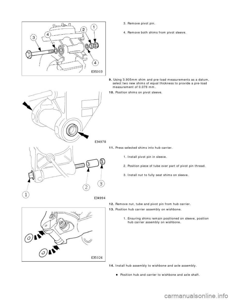
3
. Remove pivot pin.
4. Remove both shims from pivot sleeve.
9. Using 3.905mm shim and pre-load measurements as a datum,
select two new shims of equal thickness to provide a pre-load
measurement of 0.076 mm.
10
.
Position shims on pivot sleeve.
11
.
Press selected shims into hub carrier.
1. Install pivot pin in sleeve.
2. Position piece of tube ov er part of pivot pin thread.
3. Install nut to fully seat shims on sleeve.
12. Remove nut, tube and pivot pin from hub carrier.
13
.
Position hub carrier as sembly on wishbone.
1. Ensuring shims remain posi tioned on sleeve, position
hub carrier assembly on wishbone.
14. Install hub assembly to wi shbone and axle assembly.
Position hu
b and carrier to wishbone and axle shaft.
Page 256 of 2490
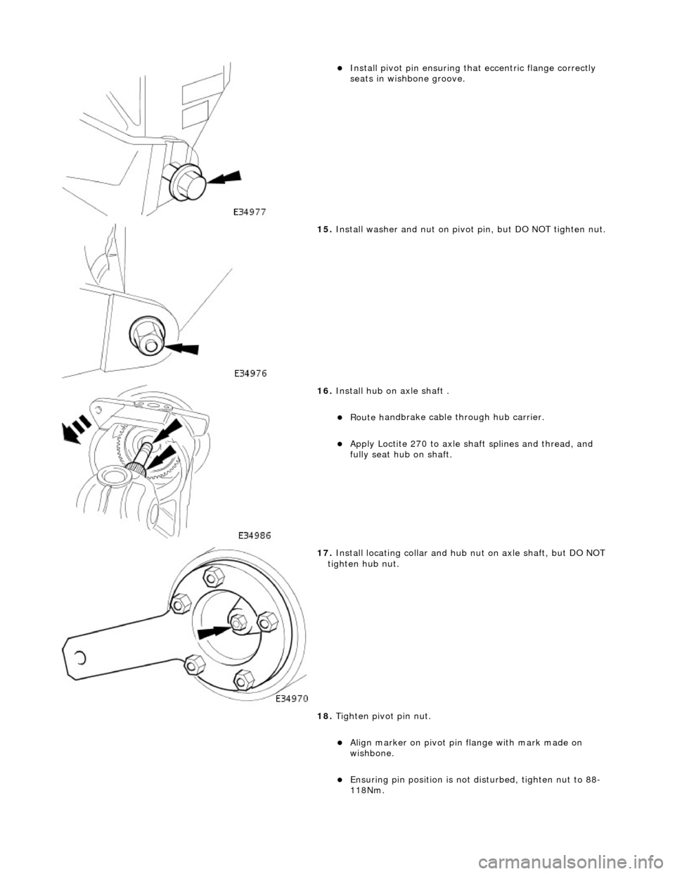
Install pivo
t pin ensuring that
eccentric flange correctly
seats in wishbone groove.
15 . Inst
all washer and nut on pivot pin, but DO NOT tighten nut.
16 . Install hu
b on axle shaft .
Rout
e h
andbrake cable through hub carrier.
Appl
y Loct
ite 270 to axle shaft splines and thread, and
fully seat hub on shaft.
17 . Inst
all locating collar and hub nut on axle shaft, but DO NOT
tighten hub nut.
18. Tighten pivot pin nut.
Align mark
er on pivot pin flange with mark made on
wishbone.
Ensuri ng pi
n position is not
disturbed, tighten nut to 88-
118Nm.
Page 257 of 2490

19
.
Install wheel speed sensor on hub carrier.
Posit
ion sensor on hub carrier
and install and tighten bolt
to 7-10Nm.
Conne
ct wheel speed sensor harness to sensor.
20
.
Using new tie strap, secure wh eel speed sensor harness to
brake hose clip.
21. Install parking brake shoe s. Refer to 70.40.05.
22
.
Install special tool (204-195) on studs and install securing
nuts.
23. Tighten hub nut to 304-336Nm.
Page 258 of 2490
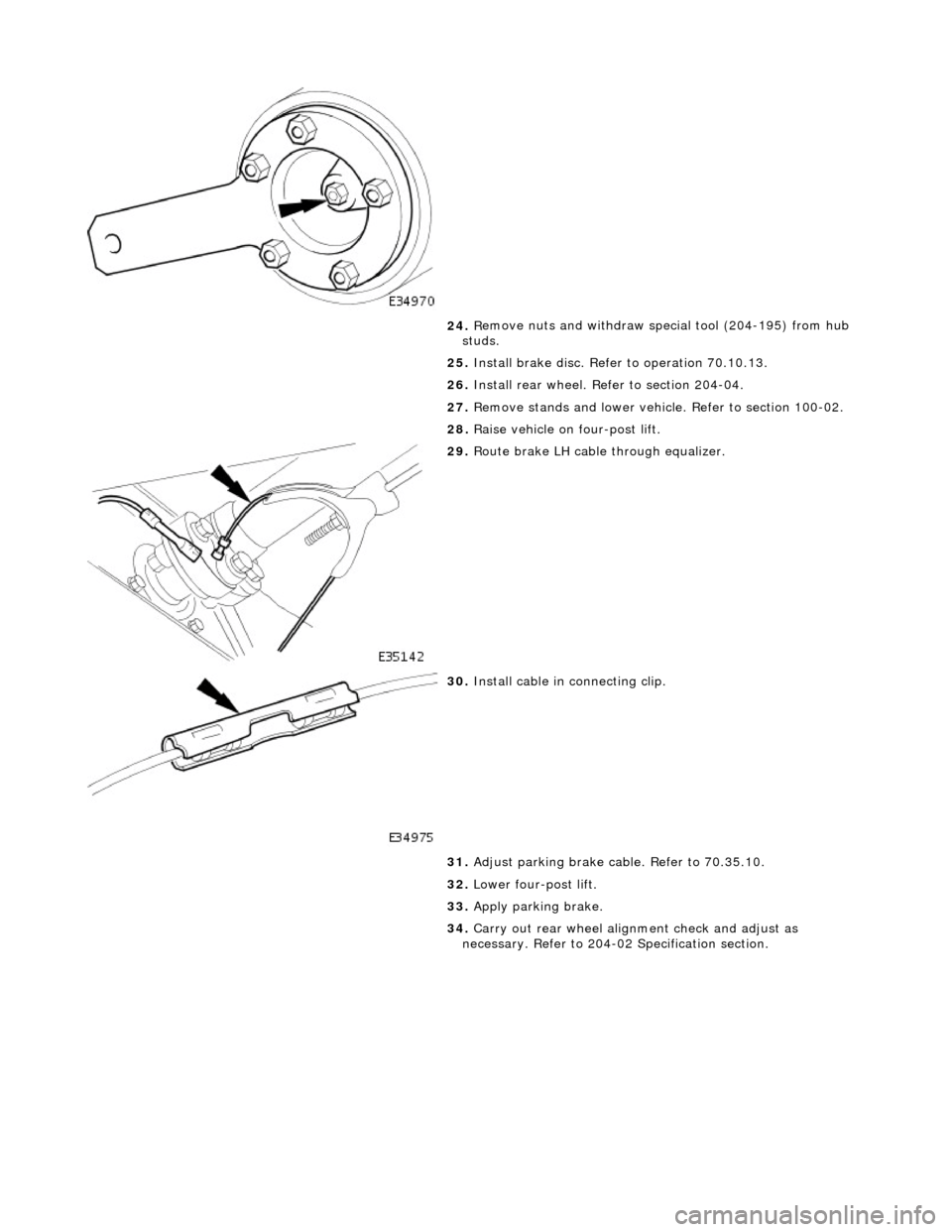
24
. R
emove nuts and withdraw special tool (204-195) from hub
studs.
25. Install brake disc. Refer to operation 70.10.13.
26. Install rear wheel. Refer to section 204-04.
27. Remove stands and lower vehicl e. Refer to section 100-02.
28. Raise vehicle on four-post lift.
29 . Rout
e brake LH cable through equalizer.
30 . Inst
all cable in connecting clip.
31. Adjust parking brake cable. Refer to 70.35.10.
32. Lower four-post lift.
33. Apply parking brake.
34. Carry out rear wheel alignm ent check and adjust as
necessary. Refer to 204-02 Specification section.
Page 259 of 2490
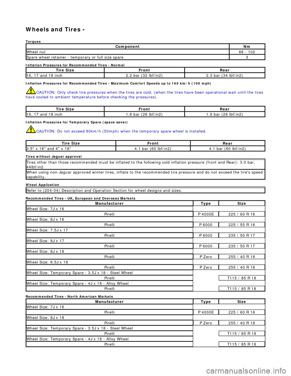
W
heels and Tires -
Torq
ues
Inflation Pressures for Recommended Tires - Normal
Inflation Pressures for Recommended Tires - Maxi mum Comfort Speeds up to 160 km/h (100 mph)
CAUTI
ON: Only check tire pressures when
the tires are cold, (when the tires have been operational wait until the tires
have cooled to ambient temperature before checking the pressures).
Inf
lation Pressures for Temporary Spare (space saver)
CAU
TION: Do not exceed 80km/h (50mph) when the temporary spare
wheel is installed.
Tires
without Jaguar approval
Wheel Application
Recommended Tires - UK, European and Overseas Markets
Recommended Tires - North American Markets
Com
ponent
Nm
Wh
eel nut
8
8 - 102
Spare wheel r
etainer - temporary or full size spare
3
Ti
re Size
Fr
ont
Rear
1
6, 17 and 18 inch
2.
2 bar (32 lbf/in2)
2.
3 bar (34 lbf/in2)
Ti
re Size
Fr
ont
Rear
1
6, 17 and 18 inch
1.
8 bar (26 lbf/in2)
1.
9 bar (28 lbf/in2)
Ti
re Size
Fr
ont
Rear
3.
5" x 18" and 4" x 18"
4.
1 bar (60 lbf/in2)
4.
1 bar (60 lbf/in2)
Ti
res other than those recommended must be inflated to the following cold
inflation pressure (front and Rear): 3.0 bar,
44lbf/in2
Wh
en using non-Jaguar approved winter ti
res, inflate to the recommended tire pressure and do not exceed the tire's speed
capability.
R
efer to (204-04) Description and Operation Section for wheel designs and sizes.
Manufact
urer
Ty
pe
Si
ze
W
heel Size: 7J x 16
Pire
lli
P 40
00E
2
25 / 60 R 16
W
heel Size: 8J x 16
Pire
lli
P 60
00
2
25 / 55 R 16
Wh
eel Size: 7.5J x 17
Pire
lli
P 60
00
2
35 / 50 R 17
W
heel Size: 8J x 17
Pire
lli
P 60
00
2
35 / 50 R 17
W
heel Size: 8J x 18
Pire
lli
P Ze
ro
2
55 / 40 R 18
Wh
eel Size: 8.5J x 18
Pire
lli
P Ze
ro
2
55 / 40 R 18
Wh
eel Size: Temporary Spare - 3.5J x 18 - Steel Wheel
Pire
lli
T1
15 / 85 R 18
W
heel Size: Temporary Spare - 4J x 18 - Alloy Wheel
Pire
lli
T1
15 / 85 R 18
Manufact
urer
Ty
pe
Si
ze
W
heel Size: 7J x 16
Pire
lli
P 40
00E
2
25 / 60 R 16
W
heel Size: 8J x 18
Pire
lli
P Ze
ro
2
55 / 40 R 18
Wh
eel Size: Temporary Spare - 3.5J x 18 - Steel Wheel
Pire
lli
T1
15 / 85 R 18
W
heel Size: Temporary Spare - 4J x 18 - Alloy Wheel
Pire
lli
T1
15 / 85 R 18
Page 260 of 2490
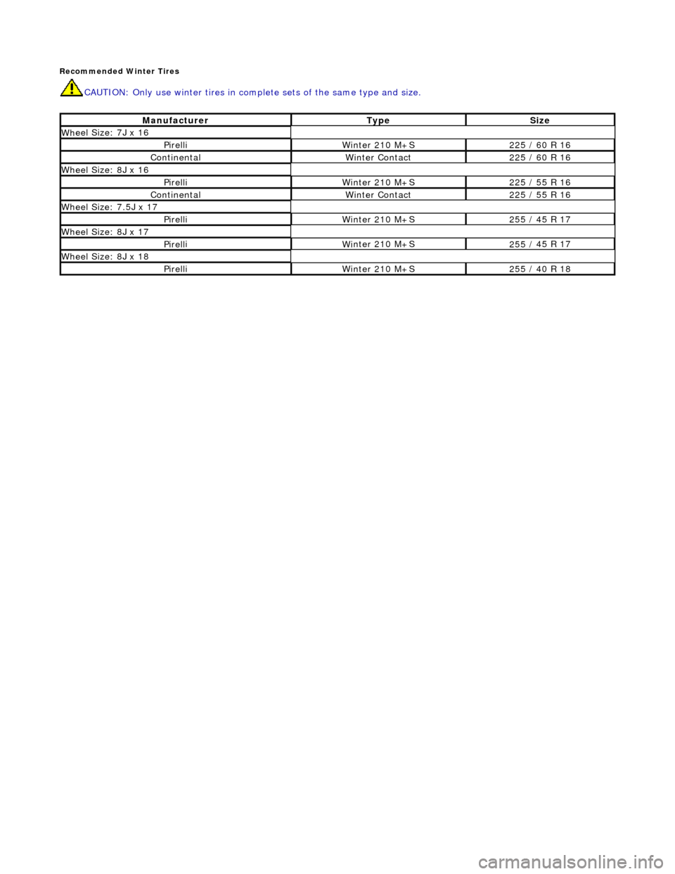
Reco
mmended Winter Tires
CAUTI
O
N: Only use winter tires in comp
lete sets of the same type and size.
Manufact urerTypeSize
Wh
eel Size: 7J x 16
Pire
ll
i
W
i
nter 210 M+S
2
25 /
60 R 16
ContinentalWint
er Cont
act
2
25 /
60 R 16
Wh
eel Size: 8J x 16
Pirell
i
Wi
nter 210 M+S
225 /
55 R 16
ContinentalWinter Cont
act
225 /
55 R 16
Whee
l Size: 7.5J x 17
Pirell
i
Wi
nter 210 M+S
255 /
45 R 17
Wh
eel Size: 8J x 17
Pire
ll
i
W
i
nter 210 M+S
2
55 /
45 R 17
W
h
eel Size: 8J x 18
Pire
ll
i
W
i
nter 210 M+S
2
55 /
40 R 18