battery JAGUAR X308 1998 2.G Workshop Manual
[x] Cancel search | Manufacturer: JAGUAR, Model Year: 1998, Model line: X308, Model: JAGUAR X308 1998 2.GPages: 2490, PDF Size: 69.81 MB
Page 1762 of 2490
Climate Control System - General Infor
mation - Air Conditioning (A/C)
System Recovery, Evacuation and Charging
Gen e
ral Procedures
Recover / Reclaim
Ev
acuation
Charging
1.
CAUTIO
N: Read the procedures and instructions supplied
by the manufacturer of the air co nditioning service center before
commencing any process requiring the handling of refrigerant. In
addition to the manufacturer's in formation, observe all safety
precautions and advice deta iled in this section.
Disconnect battery ground lead; refer to 86.15.19.
2. Remove passenger side fi
rewall cover.
3. Remove driver side firewall cover.
4. Remove engine compar tment rear cover.
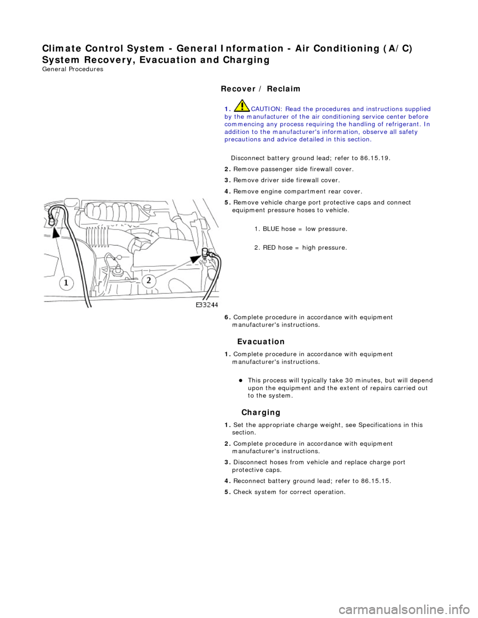
5. Re
move vehicle charge port
protective caps and connect
equipment pressure hoses to vehicle.
1. BLUE hose = low pressure.
2. RED hose = high pressure.
6. Complete procedure in ac cordance with equipment
manufacturer's instructions.
1. Complete procedure in ac cordance with equipment
manufacturer's instructions.
пЃ¬This proc
ess will typically ta
ke 30 minutes, but will depend
upon the equipment and the ex tent of repairs carried out
to the system.
1. Set the appropriate charge weight, see Specifications in this
section.
2. Complete procedure in ac cordance with equipment
manufacturer's instructions.
3. Disconnect hoses from vehicle and replace charge port
protective caps.
4. Reconnect battery ground lead; refer to 86.15.15.
5. Check system for correct operation.
Page 1777 of 2490
Air Distribution and Filtering - Center Registers
Removal and Installation
Removal
Installation
1.
Remove battery cover and disconnect ground cable from battery
terminal. Refer to 86.15.19.
2. Remove passenger airbag deployment door for access. Refer to
Section 501-20.
3. Remove major gauge module veneer panel for access. Refer to
76.47.24.
4. Carefully withdraw fascia centre veneer panel.
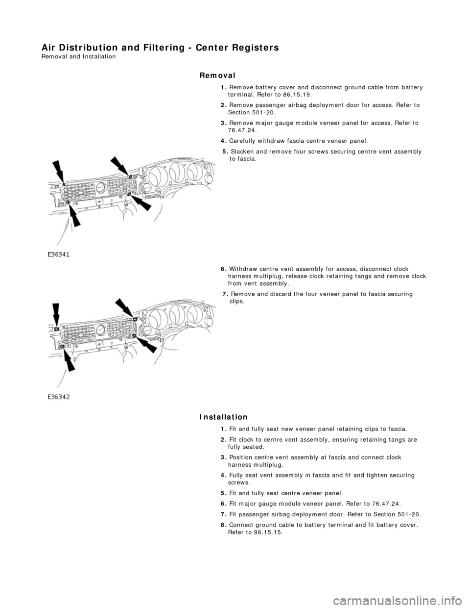
5. Slacken and remove four screws securing centre vent assembly
to fascia.
6. Withdraw centre vent assembly for access, disconnect clock
harness multiplug, release clock retaining tangs and remove clock
from vent assembly.
7. Remove and discard the four veneer panel to fascia securing
clips.
1. Fit and fully seat new veneer panel retaining clips to fascia.
2. Fit clock to centre vent assemb ly, ensuring retaining tangs are
fully seated.
3. Position centre vent assembly at fascia and connect clock
harness multiplug.
4. Fully seat vent assembly in fascia and fit and tighten securing
screws.
5. Fit and fully seat centre veneer panel.
6. Fit major gauge module veneer panel. Refer to 76.47.24.
7. Fit passenger airbag deployment door. Refer to Section 501-20.
8. Connect ground cable to battery terminal and fit battery cover.
Refer to 86.15.15.
Page 1788 of 2490
Heating and Ventilation - Heater Core and Evaporator Core Housing
Removal and Installation
Removal
1. Disconnect battery ground cable (IMPORTANT, see SRO
86.15.19 for further information).
2. Recover refrigerant from air co nditioning system; refer to
82.30.30.
3. Drain radiator coolant only; refer to 26.10.01 or (SC)
26.10.01.
4. Remove instrument panel for access, refer to 76.46.01.
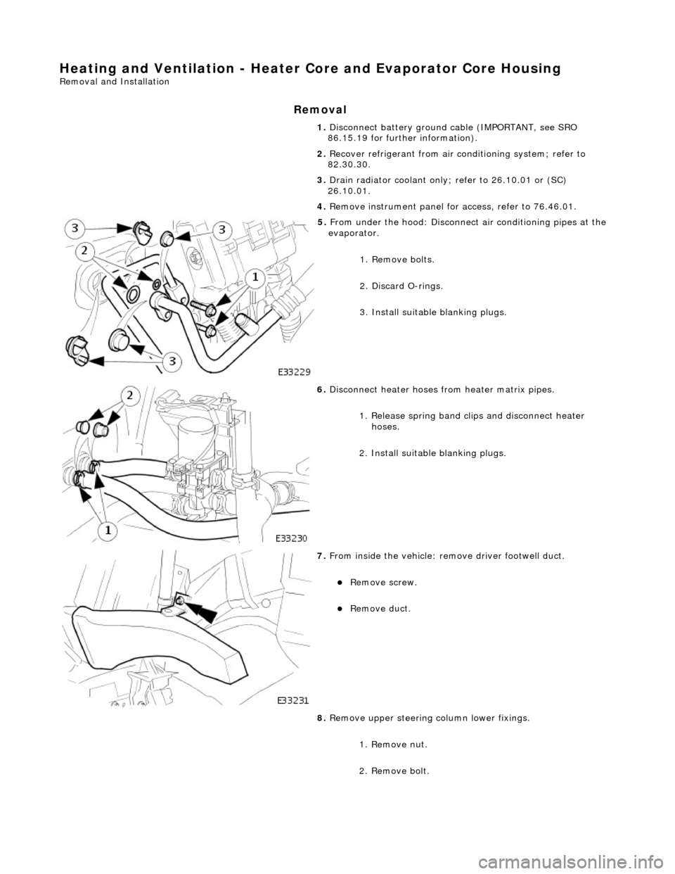
5. From under the hood: Disconnect air conditioning pipes at the
evaporator.
1. Remove bolts.
2. Discard O-rings.
3. Install suitable blanking plugs.
6. Disconnect heater hoses from heater matrix pipes.
1. Release spring band clips and disconnect heater hoses.
2. Install suitable blanking plugs.
7. From inside the vehicle: re move driver footwell duct.
пЃ¬Remove screw.
пЃ¬Remove duct.
8. Remove upper steering column lower fixings.
1. Remove nut.
2. Remove bolt.
Page 1797 of 2490
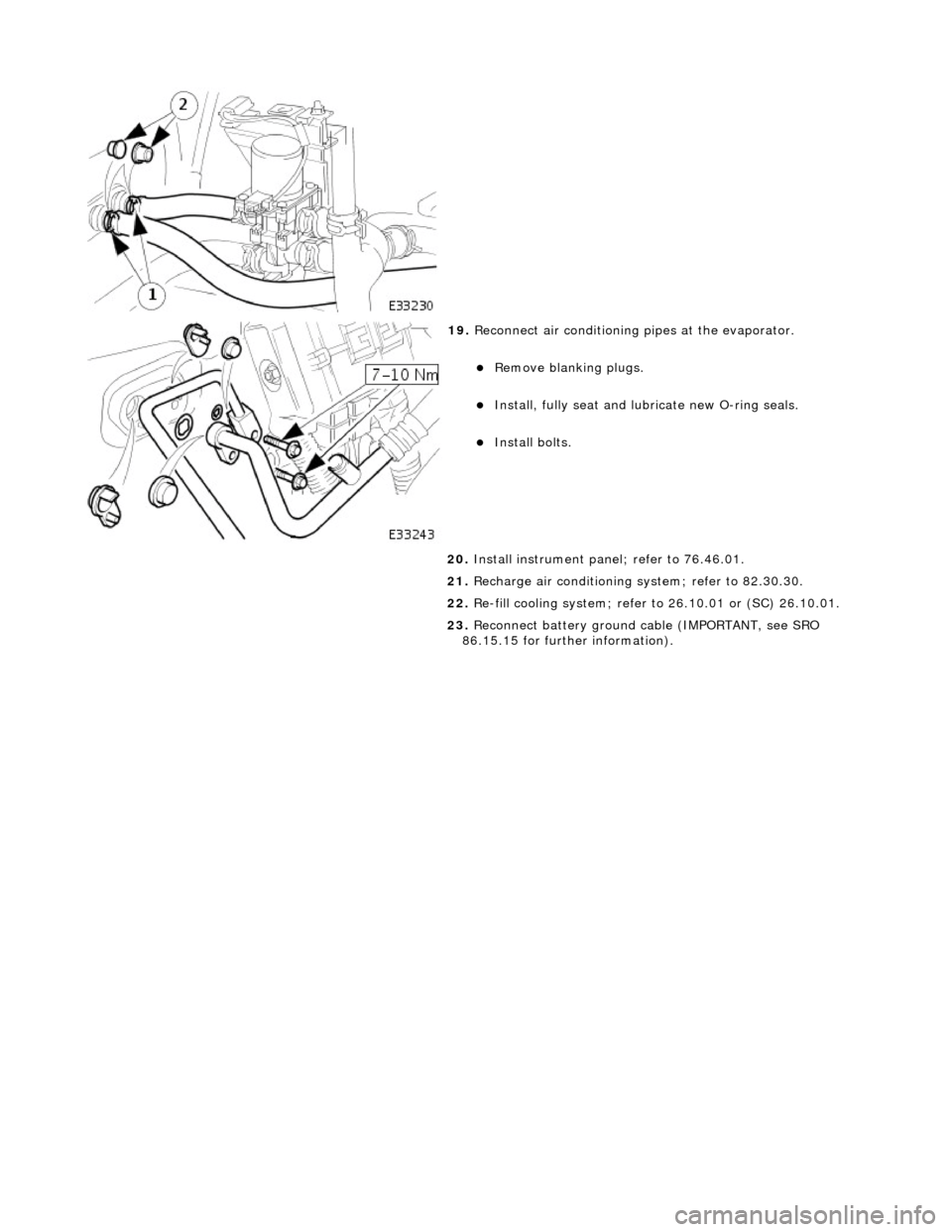
19. Reconnect air conditioning pipes at the evaporator.
пЃ¬Remove blanking plugs.
пЃ¬Install, fully seat and lubr icate new O-ring seals.
пЃ¬Install bolts.
20. Install instrument pane l; refer to 76.46.01.
21. Recharge air conditioning system; refer to 82.30.30.
22. Re-fill cooling system; refer to 26.10.01 or (SC) 26.10.01.
23. Reconnect battery ground cable (IMPORTANT, see SRO
86.15.15 for further information).
Page 1804 of 2490
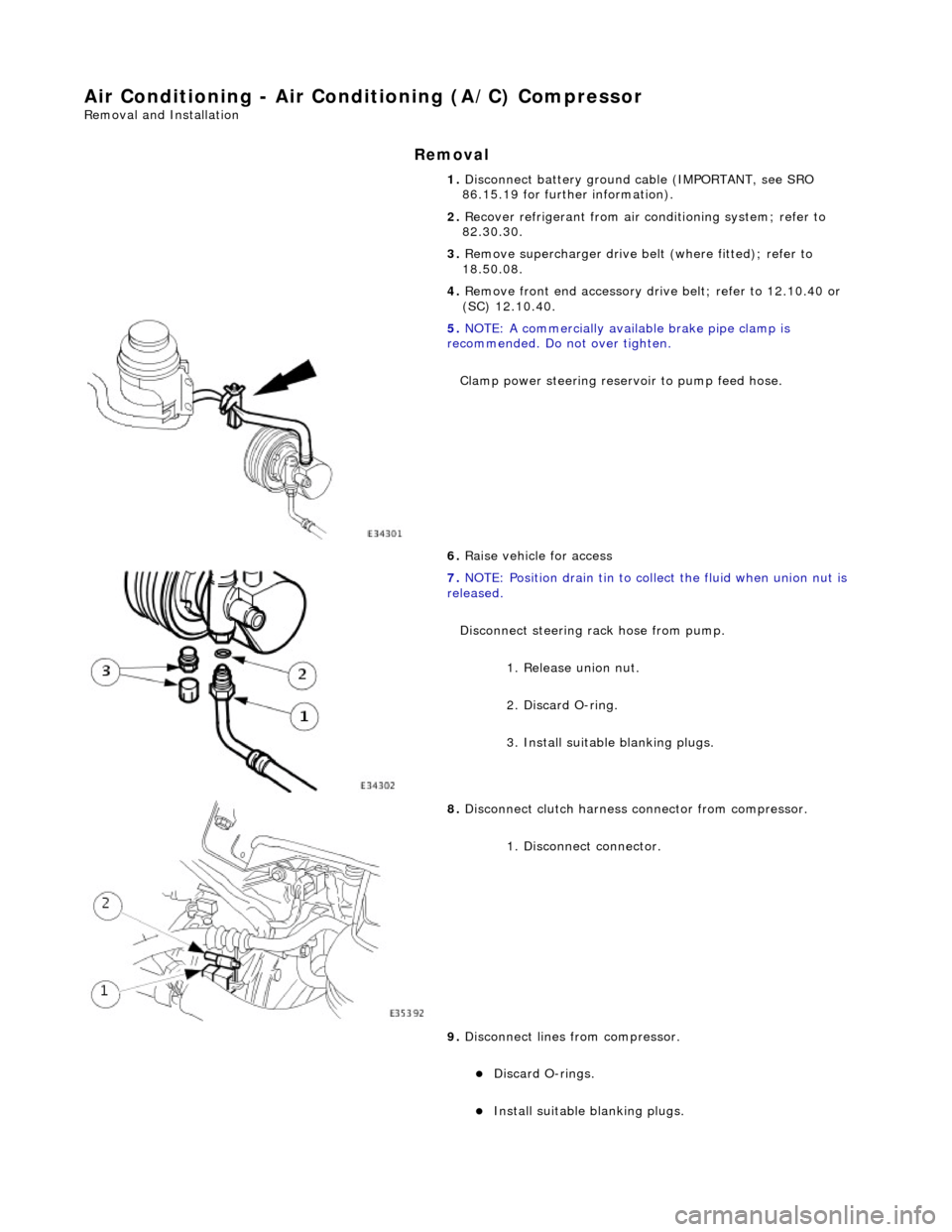
Air Conditioning - Air Conditioning (A/C) Compressor
Removal and Installation
Removal
1. Disconnect battery ground cable (IMPORTANT, see SRO
86.15.19 for further information).
2. Recover refrigerant from air co nditioning system; refer to
82.30.30.
3. Remove supercharger drive belt (where fitted); refer to
18.50.08.
4. Remove front end accessory dr ive belt; refer to 12.10.40 or
(SC) 12.10.40.
5. NOTE: A commercially availa ble brake pipe clamp is
recommended. Do not over tighten.
Clamp power steering reservoir to pump feed hose.
6. Raise vehicle for access
7. NOTE: Position drain tin to collect the fluid when union nut is
released.
Disconnect steering rack hose from pump. 1. Release union nut.
2. Discard O-ring.
3. Install suitable blanking plugs.
8. Disconnect clutch harness connector from compressor.
1. Disconnect connector.
9. Disconnect lines from compressor.
пЃ¬Discard O-rings.
пЃ¬Install suitable blanking plugs.
Page 1807 of 2490

8. Install front end accessory drive belt; refer to 12.10.40 or (SC)
12.10.40.
9. Install supercharger drive belt (where fitted); refer to
18.50.08.
10. Reconnect battery ground cable (IMPORTANT, see SRO
86.15.15 for further information).
11. Recharge air conditioning system; refer to 82.30.30.
12. Check / bleed / top up power stee ring fluid reservoir; refer to
211-02.
Page 1808 of 2490

Air Conditioning - Condenser Core
Removal and Installation
Removal
1. Disconnect battery ground cable (IMPORTANT, see SRO
86.15.19 for further information).
2. Drain radiator coolant only; refer to 26.10.01 or (SC)
26.10.01.
3. Recover refrigerant from air co nditioning system; refer to
82.30.30.
4. Release both gas struts, set the engine cover fully forward to
the service access position an d support with a wooden (or
similar) strut.
5. CAUTION: Take care not to damage hood or radiator
grille.
Remove twin fan and motor as sembly; refer to 26.25.12.
6. Disconnect radiator bleed hose.
пЃ¬Release connection.
7. Remove retaining clip which secures transmission oil cooler
upper and lower pipes.
8. Disconnect transmission oil cooler lower pipe from radiator.
1. Release union nut and disconne ct pipe.
пЃ¬Discard O-ring seal.
2. Install suitable blanking plugs.
9. From above the vehicle, discon nect transmission oil cooler
upper pipe from radiator.
1. Release union nut and disconne ct pipe.
пЃ¬Discard O-ring seal.
2. Install suitable blanking plugs.
Page 1815 of 2490
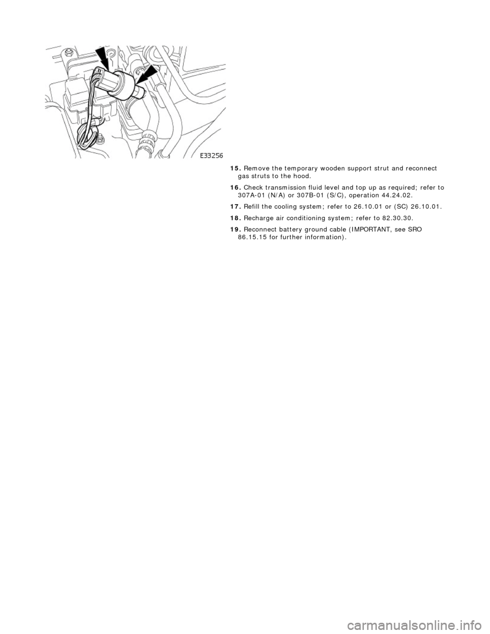
15. Remove the temporary wooden support strut and reconnect
gas struts to the hood.
16. Check transmission fluid level an d top up as required; refer to
307A-01 (N/A) or 307B-01 (S/C), operation 44.24.02.
17. Refill the cooling system; refer to 26.10.01 or (SC) 26.10.01.
18. Recharge air conditioning system; refer to 82.30.30.
19. Reconnect battery ground cable (IMPORTANT, see SRO
86.15.15 for further information).
Page 1819 of 2490
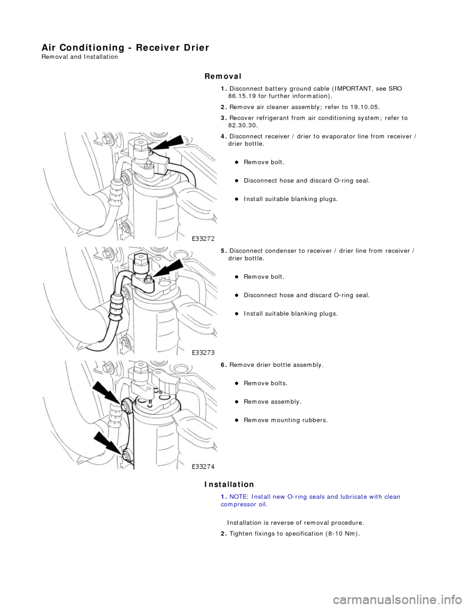
Air Conditioning - Receiver Drier
Removal and Installation
Removal
Installation
1. Disconnect battery ground cable (IMPORTANT, see SRO
86.15.19 for further information).
2. Remove air cleaner assemb ly; refer to 19.10.05.
3. Recover refrigerant from air co nditioning system; refer to
82.30.30.
4. Disconnect receiver / drier to evaporator line from receiver /
drier bottle.
пЃ¬Remove bolt.
пЃ¬Disconnect hose and discard O-ring seal.
пЃ¬Install suitable blanking plugs.
5. Disconnect condenser to receiver / drier line from receiver /
drier bottle.
пЃ¬Remove bolt.
пЃ¬Disconnect hose and discard O-ring seal.
пЃ¬Install suitable blanking plugs.
6. Remove drier bottle assembly.
пЃ¬Remove bolts.
пЃ¬Remove assembly.
пЃ¬Remove mounting rubbers.
1. NOTE: Install new O-ring seals and lubricate with clean
compressor oil.
Installation is reverse of removal procedure.
2. Tighten fixings to specification (8-10 Nm).
Page 1835 of 2490
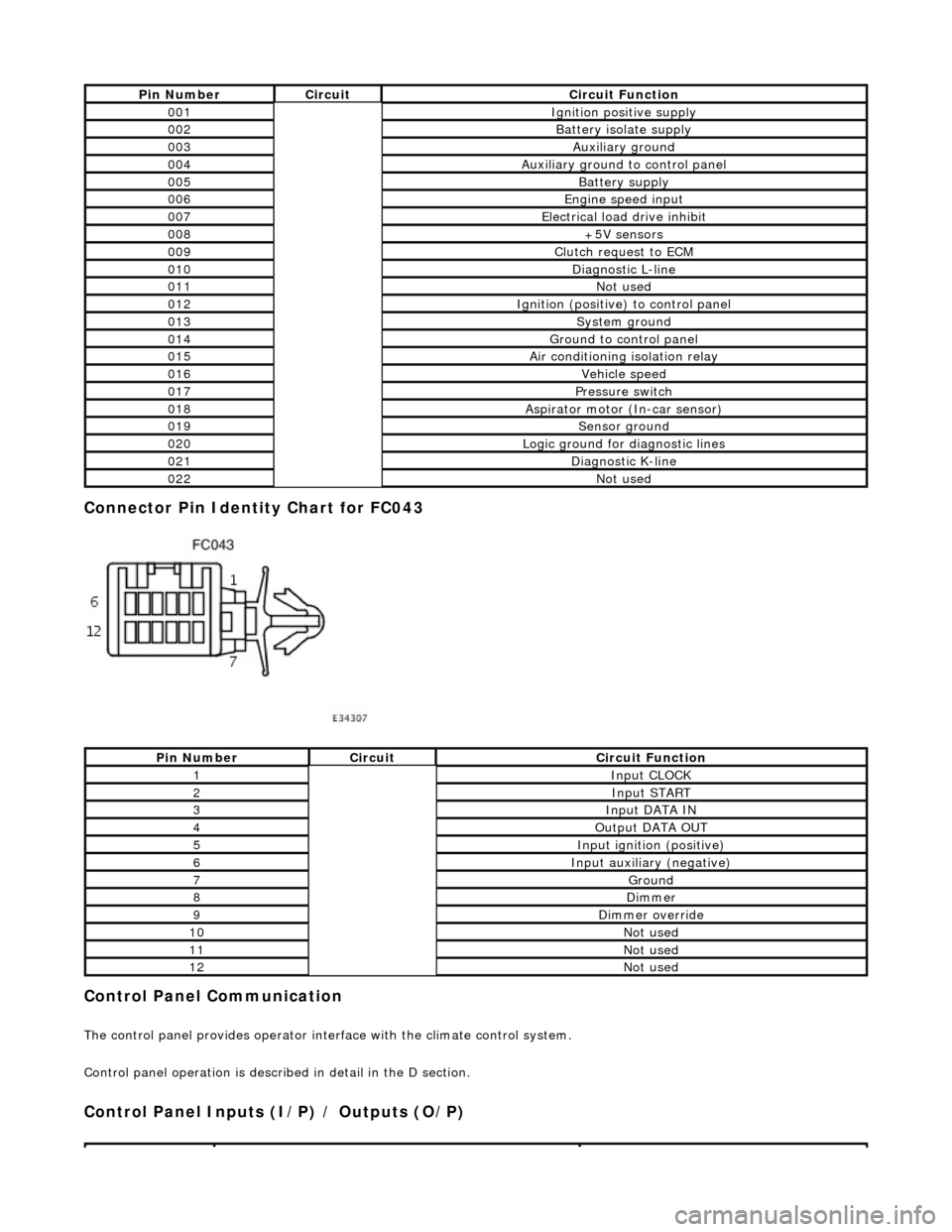
Connector Pin Identity Chart for FC043
Control Panel Communication
The control panel provides operator interface with the climate control system.
Control panel operation is described in detail in the D section.
Control Panel Inputs (I/P) / Outputs (O/P)
Pin NumberCircuitCircuit Function
001Ignition positive supply
002Battery isolate supply
003Auxiliary ground
004Auxiliary ground to control panel
005Battery supply
006Engine speed input
007Electrical load drive inhibit
008+5V sensors
009Clutch request to ECM
010Diagnostic L-line
011Not used
012Ignition (positive) to control panel
013System ground
014Ground to control panel
015Air conditioning isolation relay
016Vehicle speed
017Pressure switch
018Aspirator motor (In-car sensor)
019Sensor ground
020Logic ground for diagnostic lines
021Diagnostic K-line
022Not used
Pin NumberCircuitCircuit Function
1Input CLOCK
2Input START
3Input DATA IN
4Output DATA OUT
5Input ignition (positive)
6Input auxiliary (negative)
7Ground
8Dimmer
9Dimmer override
10Not used
11Not used
12Not used