JAGUAR X308 1998 2.G Workshop Manual
X308 1998 2.G
JAGUAR
JAGUAR
https://www.carmanualsonline.info/img/21/7640/w960_7640-0.png
JAGUAR X308 1998 2.G Workshop Manual
Page 1691 of 2490
Fuel System - Gener
al Information - Fuel Tank Draining
Gen
eral Procedures
1.
WARNING: BEFORE PROCEEDING, IT IS ESSENTIAL THAT
THE WARNING NOTES GIVEN IN SECTION 100-00 (UNDER THE
HEADING 'SAFETY PRECAUTIONS') ARE READ AND
UNDERSTOOD.
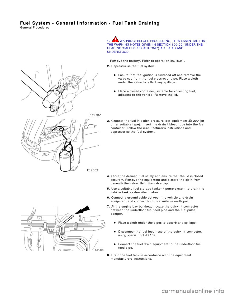
Remove the battery. Refer to operation 86.15.01.
2. De
pressurise the fuel system.
пЃ¬E
nsure that the ignition is
switched off and remove the
valve cap from the fuel cross-over pipe. Place a cloth
under the valve to collect any spillage.
пЃ¬Pla
ce a closed container, su
itable for collecting fuel,
adjacent to the vehicle. Remove the lid.
3. Conne
ct the fuel injection pressu
re test equipment JD 209 (or
other suitable type). Insert the drain / bleed tube into the fuel
container. Follow the manufa cturer's instructions and
depressurise the fuel system.
4. Store the drained fuel safely and ensure that the lid is closed
securely. Remove the equipmen t and discard the cloth from
beneath the valve. Refit the valve cap.
5. Use a suitable fuel storage tank er / pump system to drain the
vehicle tank as described below.
6. Connect a ground cable betw een the vehicle and drain
equipment and connect both to a suitable earth point.
7. At the engine bay bulkhead, lo cate the quick fit connecto
r
between the underfloor fuel feed pipe and the fuel pulse
damper.
пЃ¬Pla
ce a cloth under the pipes
to absorb any spillage.
пЃ¬D
isconnect the fuel feed hose
at the quick fit connector,
using special tool JD 182.
пЃ¬Conne
ct the fuel drain equipment to the underfloor fuel
feed pipe.
8. Drain the fuel tank in accordance with the equipment
manufacturers instructions.
Page 1698 of 2490
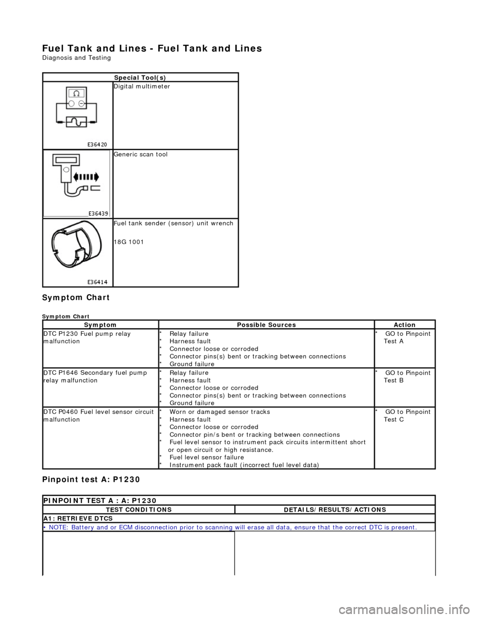
Fuel Tank and Lines - Fuel Tank and Li
nes
D
iagn
osis and Testing
Sym
p
tom Chart
Sy
m
ptom Chart
Pinpoint test A: P1230
S
p
ecial Tool(s)
D
i
gital multimeter
Generi
c scan tool
F
u
el tank sender (sensor) unit wrench
18G 1001
Sy m
ptom
Possib
l
e Sources
Acti
o
n
D
T
C P1230 Fuel pump relay
malfunction
Re lay
failure
Harness fault
Connector loose or corroded
Connector pins(s) bent or tracking between connections
Ground failure
*
*
*
*
*
GO to Pinpoint
Test A
*
D
T
C P1646 Secondary fuel pump
relay malfunction
Re lay
failure
Harness fault
Connector loose or corroded
Connector pins(s) bent or tracking between connections
Ground failure
*
*
*
*
*
GO to Pinpoint
Test B
*
D
T
C P0460 Fuel level sensor circuit
malfunction
Worn
or damaged sensor tracks
Harness fault
Connector loose or corroded
Connector pin/s bent or tracking between connections
Fuel level sensor to instrument pack circui ts intermittent short
or open circuit or high resistance. Fuel level sensor failure
Instrument pack fault (inc orrect fuel level data)
*
*
*
*
*
*
*
GO to Pinpoint
Test C
*
P
INPOINT TES
T A : A: P1230
T
E
ST CONDITIONS
D
E
TAILS/RESULTS/ACTIONS
A1
: RETRIEV
E DTCS
•
NOTE
: Battery and or ECM disconnection prior to scanning wi
ll erase all data, ensure that the correct DTC is present.
Page 1700 of 2490
Wi
th EM013 disconnected, check for battery voltage
between EM013/001 and ground BT020L.
1
B+ ?
Yes
GO t
o A13
No GO to A4
A4: CHECK
SUPPLY VOLTAGE
•
NOTE: Do not replace relay.
Page 1701 of 2490
W
ith relay 4 removed, check for battery voltage at relay
socket between pins 3 and 5.
1
B+
Yes GO to A5
No GO to A11
A5
: CHECK CIRCUIT CONTINUITY
•
NOTE: Do not replace relay.
Page 1704 of 2490
Us
ing a link lead, connect EM013/001 to ground BT020L.
1
W
i
th ignition energized, check for battery voltage at relay
socket between pins 2 and 1.
2
B+?
Yes
GO t
o A10
No GO to A8
A8: CH
ECK RELAY COIL
CIRCUIT CONTINUITY
Page 1712 of 2490
Pinpoint test B:
P1646
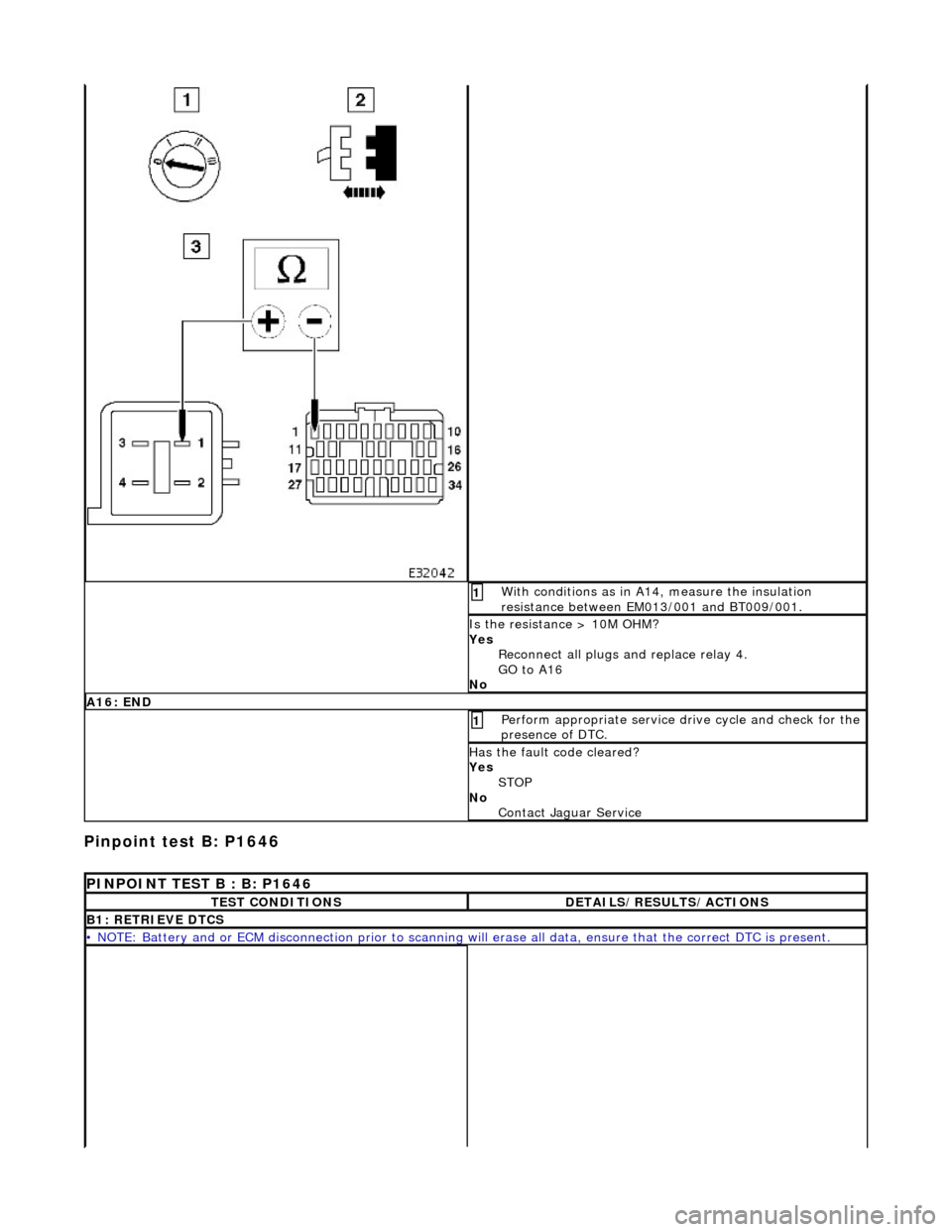
W
i
th conditions as in A14, measure the insulation
resistance between EM013/001 and BT009/001.
1
I s
the resistance > 10M OHM?
Yes Reconnect all plugs and replace relay 4.
GO to A16
No
A 16:
END
Perform
a
ppropriate service drive cycle and check for the
presence of DTC.
1
Has th
e fault code cleared?
Yes STOP
No Contact Ja
guar Serv ice
PINPOINT TEST B : B: P1646
TE
ST CONDITIONS
D
E
TAILS/RESULTS/ACTIONS
B1
: RETRI
EVE DTCS
•
NOTE
: Battery and or ECM disconnection prior to scanning wi
ll erase all data, ensure that the correct DTC is present.
Page 1714 of 2490
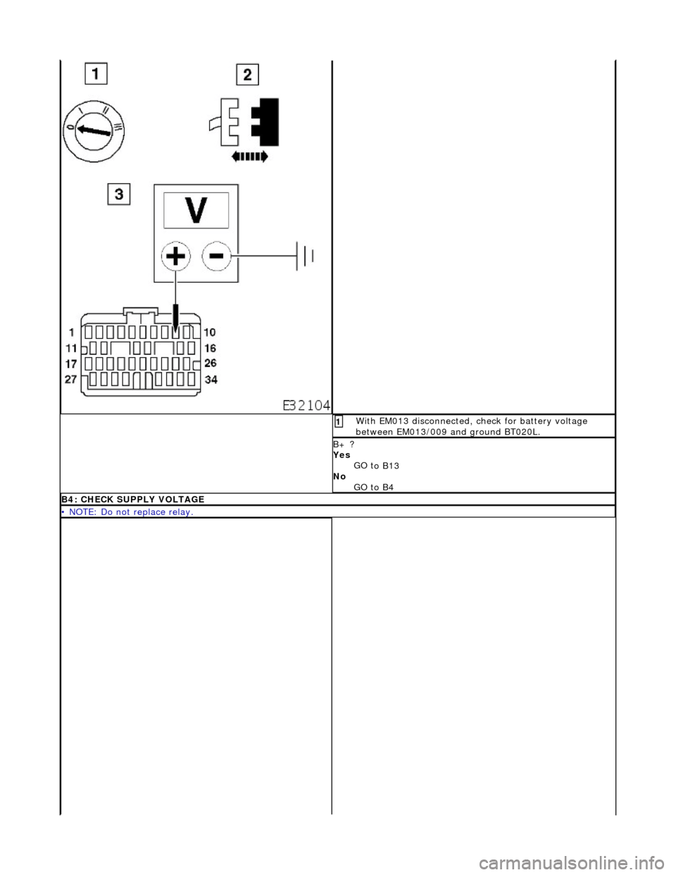
Wi
th EM013 disconnected, check for battery voltage
between EM013/009 and ground BT020L.
1
B+ ?
Yes
GO t
o B13
No GO to B4
B4: CHECK
SUPPLY VOLTAGE
•
NOTE: Do not replace relay.
Page 1715 of 2490
W
ith relay 1 removed, check for battery voltage at relay
socket between pins 3 and 5.
1
B+
Yes GO to B5
No GO to B11
B5
: CHECK CIRCUIT CONTINUITY
•
NOTE: Do not replace relay.
Page 1718 of 2490
Us
ing a link lead, connect EM013/009 to ground BT020L.
1
W
i
th ignition energized, check for battery voltage at relay
socket between pins 2 and 1.
2
B+?
Yes
GO t
o B10
No GO to B8
B8: CH
ECK RELAY COIL CIRCUIT CONTINUITY
Page 1726 of 2490
Pinpoint test C: P0460
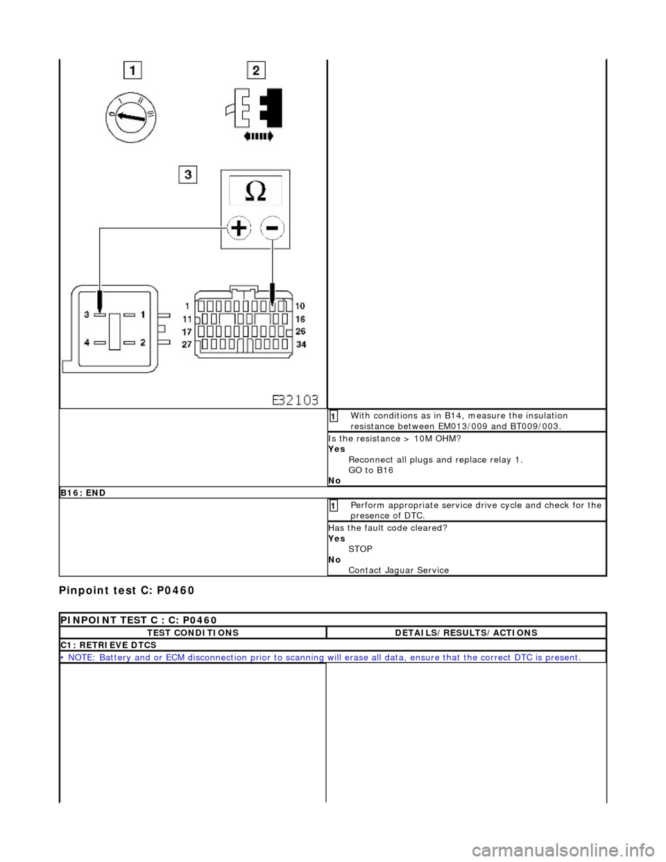
Wi
th conditions as in B14, measure the insulation
resistance between EM013/009 and BT009/003.
1
I s
the resistance > 10M OHM?
Yes Reconnect all plugs and replace relay 1.
GO to B16
No
B 16:
END
Perform
a
ppropriate service drive cycle and check for the
presence of DTC.
1
Has th
e fault code cleared?
Yes STOP
No Contact Jaguar Service
PI
NPOINT TEST C : C: P0460
T
E
ST CONDITIONS
D
E
TAILS/RESULTS/ACTIONS
C1
: RETRIEVE DTC
S
•
NOTE
: Battery and or ECM disconnection prior to scanning wi
ll erase all data, ensure that the correct DTC is present.


