body JAGUAR X308 1998 2.G Workshop Manual
[x] Cancel search | Manufacturer: JAGUAR, Model Year: 1998, Model line: X308, Model: JAGUAR X308 1998 2.GPages: 2490, PDF Size: 69.81 MB
Page 2464 of 2490

18. Disconnect steering rack transducer harness front connector.
Release harness connector from body retaining clip.
Disconnect connector.
19. Sever and discard tiestrap secu ring return pipe, harness (RHD only) and rubber support to steering rack.
20. RHD vehicles. Sever and discard tiestrap securing harness to
steering rack.
21. Route harness from behind steering return pipe.
22. Position a drain receptacle below pinion housing.
23. Remove pipe retaining plate secu ring bolt and withdraw plate.
Page 2467 of 2490
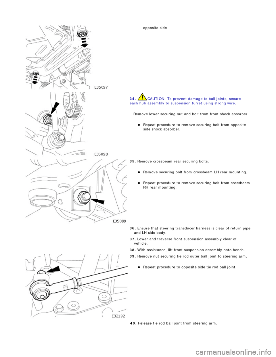
opposite side
34. CAUTION: To prevent damage to ball joints, secure
each hub assembly to suspensi on turret using strong wire.
Remove lower securing nut and bolt from front shock absorber.
Repeat procedure to remove securing bolt from opposite
side shock absorber.
35. Remove crossbeam rear securing bolts.
Remove securing bolt from crossbeam LH rear mounting.
Repeat procedure to remove securing bolt from crossbeam RH rear mounting.
36. Ensure that steering transducer harness is clear of return pipe
and LH side body.
37. Lower and traverse front suspension assembly clear of
vehicle.
38. With assistance, lift front suspension as sembly onto bench.
39. Remove nut securing tie rod oute r ball joint to steering arm.
Repeat procedure to opposite side tie rod ball joint.
40. Release tie rod ball joint from steering arm.
Page 2473 of 2490

11. Install steering rack on crossbeam.
Ensure that bushes are correct ly positioned on steering
rack.
Position steering rack on crossbeam.
Position support brac kets over bushes.
Install mounting bracket bolt s and tighten to 41-54Nm.
12. Install tie rods on steering arms.
Position and fully seat tie rod ball joint taper pin on
steering arm.
Install tie rod ball joint nu t and tighten to 71-85Nm.
Repeat procedure to install opposite side tie rod ball joint.
13. Install steering harness on suspension turret.
Noting positions marked during removal, tape new
securing clips to st eering harness.
Install securing clips/harness on LH turret.
14. With assistance position crossbeam/suspension assembly on
jack with protective wood under.
15. Traverse assembly into position below vehicle.
16. Ensure steering harn ess connector is positioned to avoid
damage during crossbeam lift .
17. NOTE: It may be necessary to use a hammer and drift to
finally align new mounting with body location.
Page 2474 of 2490

Carefully raise crossbeam assembly into position.
Ensure that dowels of both crossbeam mountings seat
correctly in body locations.
18. Ensure that both engine hydramounts seat correctly in
crossbeam locations.
19. Install crossbeam rear mountings.
Align rear mounting rubber with body location.
Install rear mounting securing bolt and nut and tighten
nut to 131-185 Nm.
Repeat procedure to install opposite side rear mounting
securing bolt and nut.
20. From engine compartment, install but do not tighten
crossbeam front RH bolts.
21. From engine compartment, install crossbeam front LH bolts
and tighten to 22-28Nm.
Page 2477 of 2490

Remove blanking plugs from pinion housing ports.
Position pipes on pinion ports and seat 'O' rings.
31. Secure pipes to pinion housing.
Ensure pipes and retaining pl ate are correctly seated.
Install bolt and tighten to 9-12Nm.
32. Secure return pipe on steering rack.
1. Position pipe rubber support on steering rack.
2. Position pipe on support .
3. RHD vehicles. Position harness on pipe support rubber.
4. Secure pipe and harness to support with new tiestrap.
33. RHD vehicles. Using new tiestrap, secure harness to steering
rack.
34. Connect steering harness.
Route harness connector to body front location.
Connect steering ha rness connector.
Install connector in body retaining clip.
Page 2481 of 2490
Uni-Body, Subframe and Mounting System - Rear Axle Crossmember
Removal and Installation
Removal
CAUTION: Replacement of nuts and bolts: Various thread-locking devices are used on nuts and bolts throughout the
vehicle. These devices restrict the number of times a nut or bolt can be used. See section 100-00 for information.
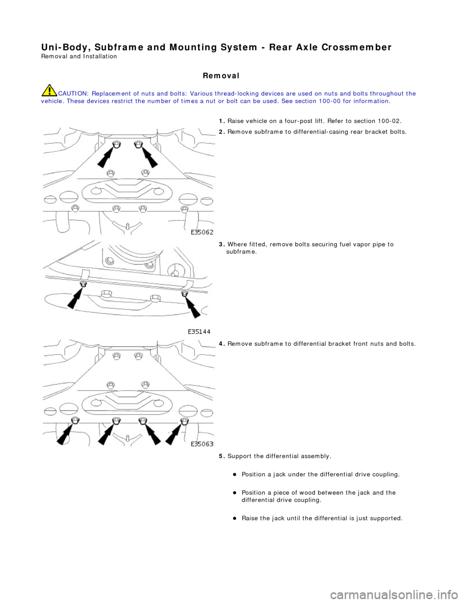
1. Raise vehicle on a four-post li ft. Refer to section 100-02.
2. Remove subframe to differentia l-casing rear bracket bolts.
3. Where fitted, remove bolts se curing fuel vapor pipe to
subframe.
4. Remove subframe to differential bracket front nuts and bolts.
5. Support the differential assembly.
Position a jack under the differential drive coupling.
Position a piece of wood between the jack and the
differential drive coupling.
Raise the jack until the diffe rential is just supported.
Page 2482 of 2490
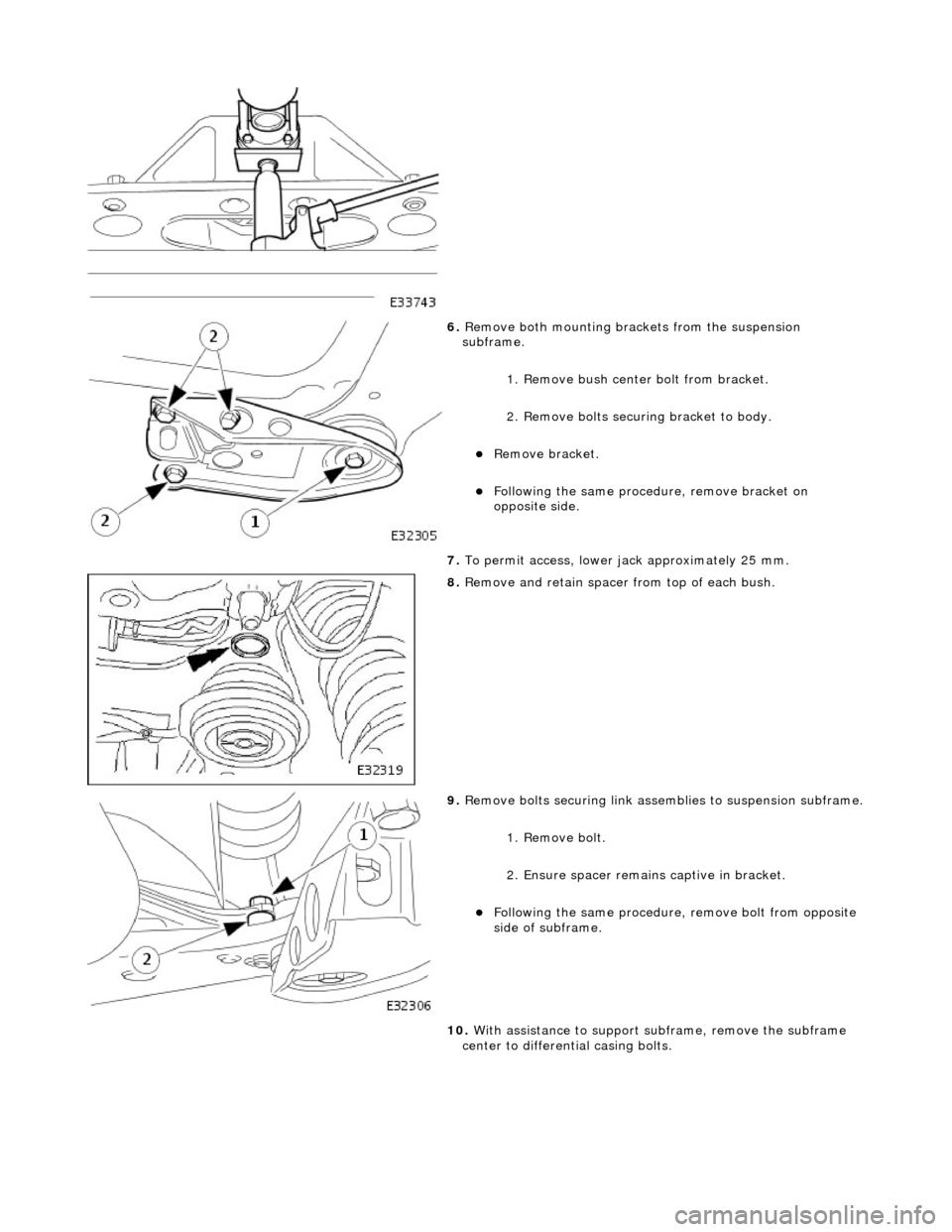
6. Remove both mounting brac kets from the suspension
subframe.
1. Remove bush center bolt from bracket.
2. Remove bolts securi ng bracket to body.
Remove bracket.
Following the same procedure, remove bracket on
opposite side.
7. To permit access, lower jack approximately 25 mm.
8. Remove and retain spacer from top of each bush.
9. Remove bolts securing link assemblies to suspension subframe.
1. Remove bolt.
2. Ensure spacer remain s captive in bracket.
Following the same procedure, remove bolt from opposite
side of subframe.
10. With assistance to support su bframe, remove the subframe
center to differential casing bolts.
Page 2485 of 2490
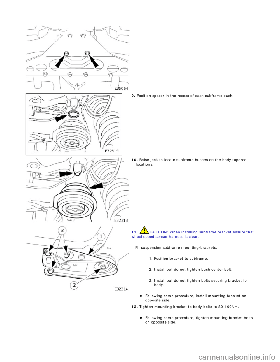
9. Position spacer in the rece ss of each subframe bush.
10. Raise jack to locate subframe bushes on the body tapered
locations.
11. CAUTION: When installing su bframe bracket ensure that wheel speed sensor harness is clear.
Fit suspension subframe mounting-brackets.
1. Position bracket to subframe.
2. Install but do not ti ghten bush center bolt.
3. Install but do not tighten bolts securing bracket to body.
Following same procedure, install mounting bracket on
opposite side.
12. Tighten mounting bracket to body bolts to 80-100Nm.
Following same procedure, ti ghten mounting bracket bolts
on opposite side.
Page 2487 of 2490
Uni-Body, Subframe and Mounting System - Rear Axle Crossmember
Bushing
Removal and Installation
Removal
CAUTION: Replacement of nuts and bolts: Various thread-locking devices are used on nuts and bolts throughout the
vehicle. These devices restrict the number of times a nut or bolt can be used. See section 100-00 for information.
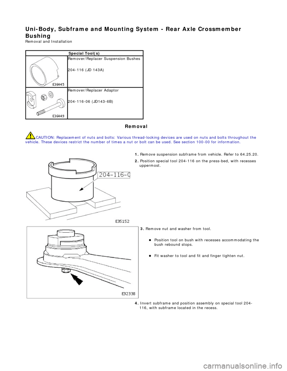
Special Tool(s)
Remover/Replacer Suspension Bushes
204-116 (JD 143A)
Remover/Replacer Adaptor
204-116-06 (JD143-6B)
1. Remove suspension subframe fro m vehicle. Refer to 64.25.20.
2. Position special tool 204-116 on the press-bed, with recesses
uppermost.
3. Remove nut and washer from tool.
Position tool on bush with recesses accommodating the
bush rebound stops.
Fit washer to tool and fit and finger tighten nut.
4. Invert subframe and position assembly on special tool 204-
116, with subframe located in the recess.