body JAGUAR X308 1998 2.G Workshop Manual
[x] Cancel search | Manufacturer: JAGUAR, Model Year: 1998, Model line: X308, Model: JAGUAR X308 1998 2.GPages: 2490, PDF Size: 69.81 MB
Page 2318 of 2490

Installation
1.
Position motor in housing and fi t and tighten securing nuts and
bolts.
2. Apply suitable lubricant to bore of new spindle inner seal and
fit seal over motor spindle.
3. Holding the capillary and purge valve clear, position
motor/housing assembly on bulkhead.
4. Seat motor spindle seal correctly in upper plenum aperture and
ensure that housing lo cates on lower studs.
5. Fit and tighten the housin g upper securing bolts.
6. Fit and tighten the housing lower securing screws and slide
locking clips inwards.
7. Position throttle cable adjustment bracket on throttle body and
fit and tighten securing bolts.
8. Position purge valve bracket at bulkhead and fit and tighten
securing bolt and nuts.
9. Position engine harness multiplu g on mounting bracket and fit
and tighten securing nut.
10. Connect motor harness multiplug and locate in retaining clip.
11. Apply suitable lubricant to bore of new outer seal and fit with
washer to motor spindle.
12. Fit and fully tighten collar nut on motor spindle.
13. Fit plenum cover. Refer to 76.10.01.
14. Fit wiper arm and blade. Refer to 84.15.44.90.
15. Fit top covers to LH and RH bulkheads and rear of engine
compartment. refer to 76.11.33 and 76.11.35.
16. Fit ground cable to battery te rminal and cover to battery.
Refer to 86.15.15.
Page 2320 of 2490
Installation
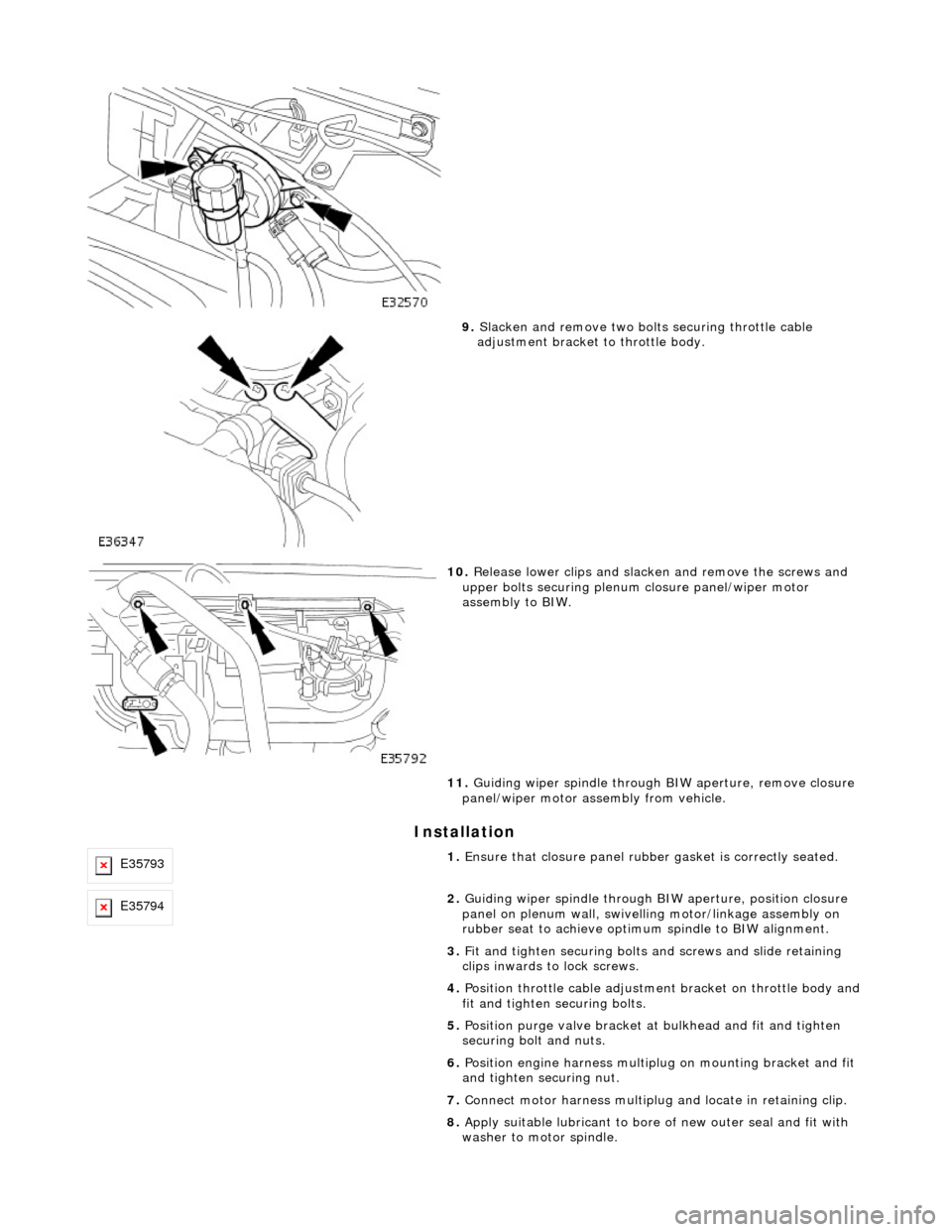
9. Slacken and remove two bolts securing throttle cable
adjustment bracket to throttle body.
10. Release lower clips and slacken and remove the screws and
upper bolts securing plenum closure panel/wiper motor
assembly to BIW.
11. Guiding wiper spindle through BIW aperture, remove closure
panel/wiper motor assembly from vehicle.
E357931. Ensure that closure panel rubbe r gasket is correctly seated.
E357942. Guiding wiper spindle through BI W aperture, position closure
panel on plenum wall, swivelling motor/linkage assembly on
rubber seat to achieve optimu m spindle to BIW alignment.
3. Fit and tighten securing bolts and screws and slide retaining
clips inwards to lock screws.
4. Position throttle cable adjustment bracket on throttle body and
fit and tighten securing bolts.
5. Position purge valve bracket at bulkhead and fit and tighten
securing bolt and nuts.
6. Position engine harness multiplu g on mounting bracket and fit
and tighten securing nut.
7. Connect motor harness multiplug and locate in retaining clip.
8. Apply suitable lubricant to bore of new outer seal and fit with
washer to motor spindle.
Page 2337 of 2490
Roof Opening Panel - Roof Opening Panel Motor
Removal and Installation
Removal
Installation
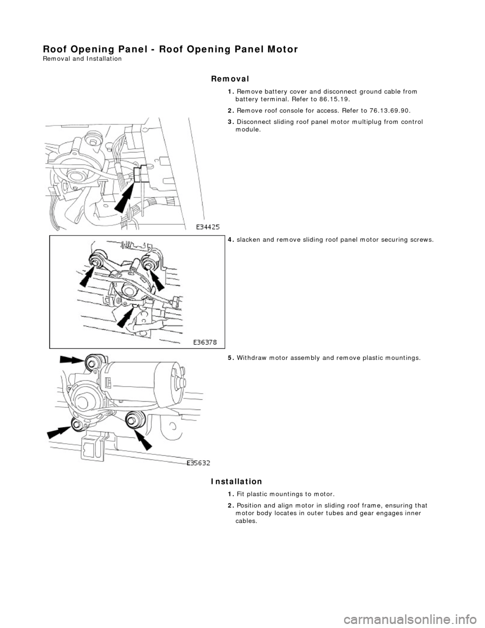
1. Remove battery cover and disc onnect ground cable from
battery terminal. Refer to 86.15.19.
2. Remove roof console for ac cess. Refer to 76.13.69.90.
3. Disconnect sliding roof panel motor multiplug from control
module.
4. slacken and remove sliding roof panel motor securing screws.
5. Withdraw motor assembly and remove plastic mountings.
1. Fit plastic mountings to motor.
2. Position and align motor in slid ing roof frame, ensuring that
motor body locates in outer tubes and gear engages inner
cables.
Page 2343 of 2490
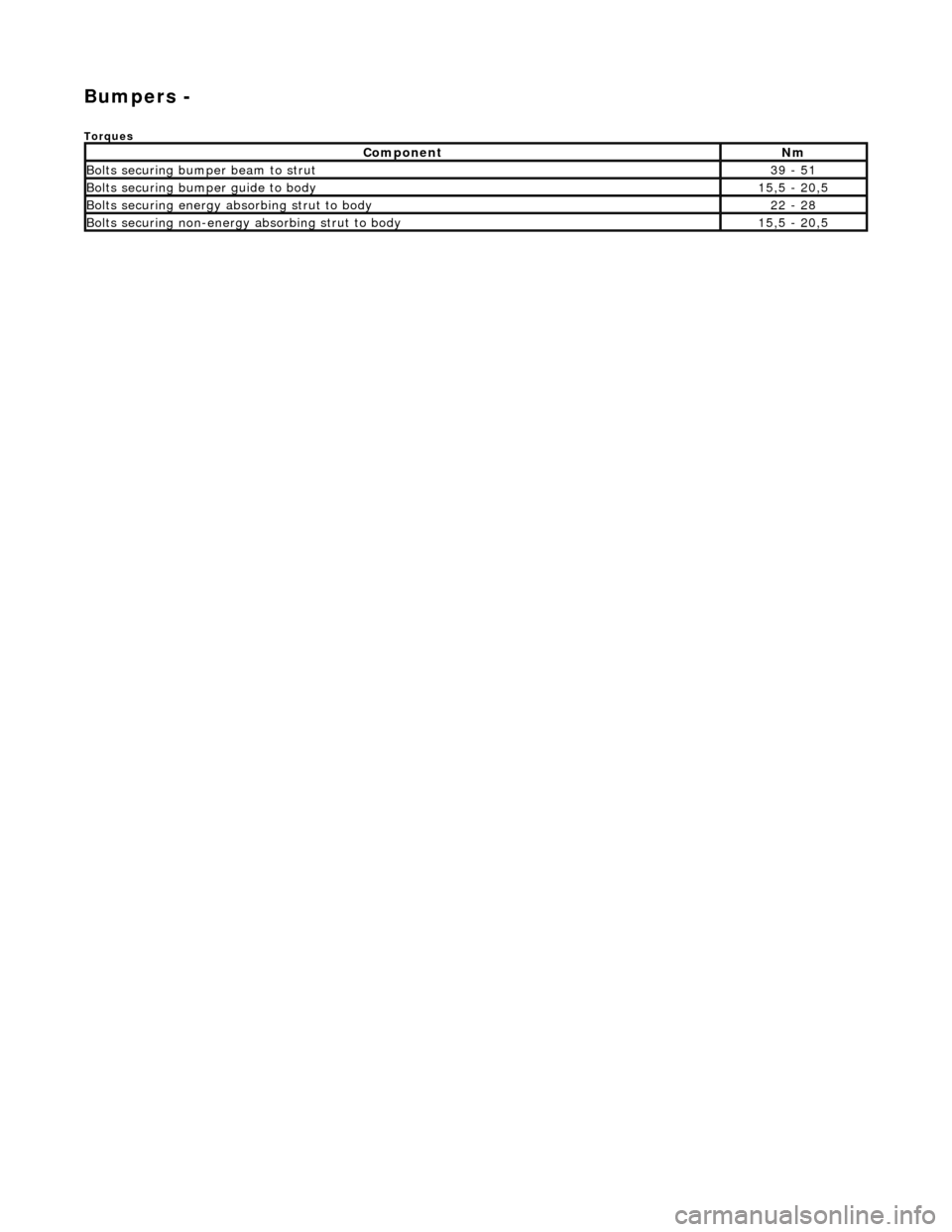
Bumpers -
Torques
ComponentNm
Bolts securing bumper beam to strut39 - 51
Bolts securing bumper guide to body15,5 - 20,5
Bolts securing energy absorbing strut to body22 - 28
Bolts securing non-energy absorbing strut to body15,5 - 20,5
Page 2380 of 2490
Body Repairs - General Information - Body Repairs
Description and Operation
Body Pre-treatment, Painting and Sealing
PVC Coated Underside
Page 2381 of 2490
The body is pre-treated to ensure high resistance to corrosion and stone chip dama ge. Prior to the first major pre-treatment process, the body shell is high-pressure washed to remove any metal dust and residual oil.
The first major pre-treatment process consists of phosphate and electro-paint deposition, which together with zinc coating,
forms the basis of the corrosion protection. This process includes high pressure knock-off, alkali de-greasing, zinc phosphate
conversion of body steel (dissolving iron and coating with zinc phosphate crystals), trivalent chrome rinsing and
demineralized water rinsing, seal ing all chemicals and impurities.
Both dip and spray techniques are employed and the bodies are submerged to the waistline during the first and third rinses
of the main phosphate clean. Chemical strengths and soluti on temperatures are continuously monitored and accurately
controlled throughout the process.
An 80% water primer is then cathodic elec tro-deposition applied to the thoroughly cleansed bodies in a uniform 'sag-free'
film 18 to 32 micron thick. Optimum durabi lity of the electroprimer is achieved by finally curing in a stoving oven at 165 °C
for a period of 20 minutes.
All underbody seams of the fully primed bo dies are then manually sealed, to prevent water and dust ingress into the vehicle
and to enhance corrosion protection.
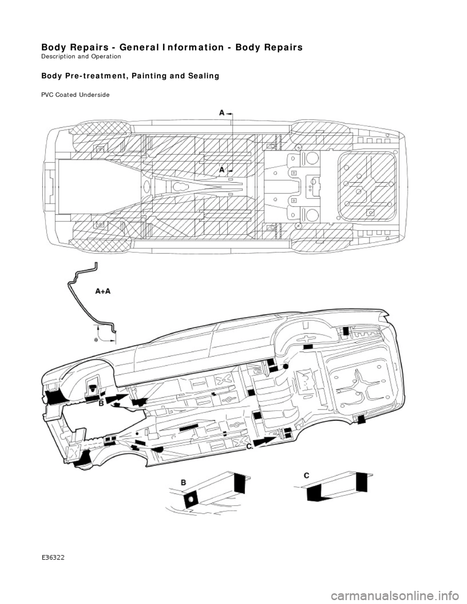
An 800 to 1000 g/m2 PVC coating is semi-automatic airless sp ray applied to the underside of the main floor panels, trunk
floor and rear wheel arches (ref. illustration above).
The upper panels of primed and external ly sealed bodyshells are next lightly scuffed to remove imperfections and a PVC
coating is applied to all internal seams by an airless spray technique. A PVC bead seal is also applied to the doors, hood and
trunk clinch joints.
Following anti-corrosion, sealing and primin g treatment, the bodies enter the first stage of 'cosmetic' painting. This consists
of the application of two coats of a highly chip resistant po lyester surfacer, employing high voltage electrostatic 'spinning
bells', to achieve a final film thickness of 35 to 50 micron. Between surfacer coats, a polyurethane coat is automatically
applied to the sills to impart even greater resistance to stone chipping.
All interior panels are then painted us ing a color keyed sealer, wet-on-wet wi th a surfacer material, after which the
bodyshells are stoved at 160 °C for a period of 20 minutes. Further protection agai nst corrosion is provided by a medium
solids black pigmented wax which is airless spray applied to vehicle undersides.
Wax Injected Box Sections
Critical body box-sections are si milarly protected by spray injecting a high solids wax. This is then re-flowed at 70 to 90 °C
to achieve optimum seam/joint penetratio n and form a resilient and durable internal coating (ref. illustration above).
After full wet sanding, rinsing and drying to provide a good su bstrate, a color-keyed semi-matt sealer co at is applied using
electrostatic bells to achieve a film build of 25 to 35 micron . The bodies are then stoved for a further 20 minutes at a
temperature of 145 °C and subjected to a local 'seek-and-find' de -nib operation prior to the final two coat process. The final
top coat finish is achieved by using poly ester base coat colors and an acrylic sag resistant clear coat. This clear over base
(COB) process produces a high gloss, durabl e paint finish with a film thickness of 50 to 65 micron, which is finally cured at a
temperature of 135°C for 20 minutes.
The Munsell three dimensional system of color management is em ployed to achieve highly accurate control of vehicle colors.
This system ensures that paint pigmentations are accurately maintained and facilitates vigorous final checking of finished
vehicles for color match. The hu e of individual panels such as trunk lids, doors and hoods is in some instances adjusted to
offset the effects of differing light angles. Where applicable, coachlines are manually applied and radiant heat cured on the
completed and valeted vehicle prior to hand spray applic ation of a protective wax coat.
Introduction
All repairs, whether structural or cosmetic must return the vehicle to the original manufactured condition with regard to
occupant safety, dimensional accuracy, fi nish and corrosion protection, and ensure continuation of the Paint Surface and
Corrosion warranty where applicable.
Similarly, repaired vehicles must be fu lly checked, and where appropriate reset, with regard to steering, suspension,
braking, and occupant restraint systems.
Page 2383 of 2490
Paint
The inhalation of sprays, fumes, or dust during paint application or sanding processes should always be avoided. Ensure
that there is efficient ventilation / extrac tion at all times. Paint spraying should be confined as far as possible to spray
booths. Personnel with a history of asth ma should not be employed in any process involving the use of isocyanates.
Operators working in a spray booth where isocyanate material is present must use air-fed breathing equipment with air
supplied to the visor at the re commended pressure and filtered to remove oil, water, and fumes. Operators involved in
handling mixing or spraying should wear protective clothing including gloves and goggles, to avoid skin and eye contact.
Particle masks or canister type respir atosr should be worn when sanding.
Applied Heat
When welding, flame cutting, brazing etc, the operator shou ld use as appropriate, goggles, mask / fume extractor and
flameproof protective clothing. It is especially important when working with polyurethane compounds to use air-fed
breathing equipment. Appropriat e fire fighting equipment and personnel trai ned in its use must always be available.
Metal Repair
Appropriate eye and hand protection should be worn when sanding, drilling, cutting, chiselling, flatting or welding. Face
masks or air-fed visors should also be wo rn when sanding or flatting either body solder or fillers. On completion of a
soldering operation, swarf must be re moved from the work area and the operat or must wash his hands thoroughly.
GENERAL REPAIR NOTES
The following advice should be noted before any repair work is carried out.
Disconnect the vehicle battery gr ound lead (disconnect the alternator where electric welding is used) and take note of the
reconnection procedures as detailed in 86.15.15.
Where structural parts are straightened or renewed, a body alignment / straightening jig must be used. The application of
heat, especially excessive heat, reduces the strength of steels, where appropriate therefore, structural sections should be
straightened by cold processes.
Repairs may only be carried out successful ly, and any warranties protected, if genuine Jaguar replacement parts and Jaguar
approved materials are used.
The correct tools, procedures and facilities must always be us ed. The quality of the work must not be compromised by using
inappropriate methods or equipment.
All trim and electrical components in the locality of the repair must be removed or disconnected prior to panel removal /
replacement; this is especially important where hollow sectio ns may contain harnesses, tubes or foam, see section A4.3.5.
WARNING: DO NOT WORK IN THE VICINITY OF A LIVE AIR BAG, REMOVE IT COMPLETELY. READ WORKING
PRACTICES AIR BAG, SECTION 20. ANY SEAT BELT WHICH HAS BEEN WORN IN AN ACCIDENT MUST BE RENEWED.
CAUTION: Electric arc welding should not be used on Jaguar vehicles. The high voltages produced by this process will
cause irreparable damage to the electric al control and microprocessor systems.
The following welding and gas processes are the only ones recommended by Jaguar Cars Ltd.
Welding and Gas Processes
Resistance spot welding, MIG welding and all gas processes may only be carried out on bare, unpainted or unplated metal.
The flanges of panels to be welded toge ther, must be clean, corrosion free and tr eated as appropriate, with either weld-
through primer or inter-weld sealer. Only materials and processes specified in the 'Body Sealing and Preservation Manual'
should be used in the relevant application areas detailed in this section. Refer to 'Zinc Coated Panels' Section
Page 2386 of 2490
Body Structure
Introduction
The standard wheelbase Jaguar sedan has a unit construction monocoque body structure with bolt-on front fenders and
welded rear fenders. The doors feature lif t-off hinges and welded drop-glass frames.
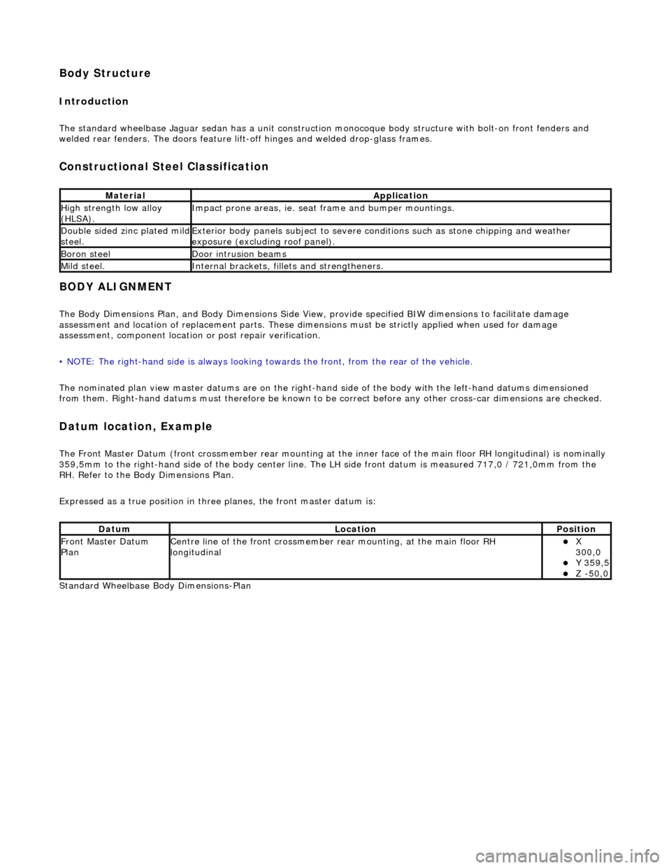
Constructional Steel Classification
BODY ALIGNMENT
The Body Dimensions Plan, and Body Dimensions Side View, provide specified BIW dimensions to facilitate damage
assessment and location of replacemen t parts. These dimensions must be strictly applied when used for damage
assessment, component location or post repair verification.
• NOTE: The right-hand side is always looking towards the front, from the rear of the vehicle.
The nominated plan view master datums are on the right-hand side of the body with the left-hand datums dimensioned
from them. Right-hand datums must therefore be known to be correct before any other cross-car dimensions are checked.
Datum location, Example
The Front Master Datum (front crossmember rear mounting at the inner face of the main floor RH longitudinal) is nominally
359,5mm to the right-hand side of the body center line. The LH side fron t datum is measured 717,0 / 721,0mm from the
RH. Refer to the Body Dimensions Plan.
Expressed as a true posi tion in three planes, the front master datum is:
Standard Wheelbase Bo dy Dimensions-Plan
MaterialApplication
High strength low alloy
(HLSA).Impact prone areas, ie. seat frame and bumper mountings.
Double sided zinc plated mild steel.Exterior body panels subject to severe cond itions such as stone chipping and weather
exposure (excluding roof panel).
Boron steelDoor intrusion beams
Mild steel.Internal brackets, fill ets and strengtheners.
DatumLocationPosition
Front Master Datum
PlanCentre line of the front crossmember rear mounting, at the main floor RH
longitudinalX
300,0
Y 359,5 Z -50,0
Page 2387 of 2490
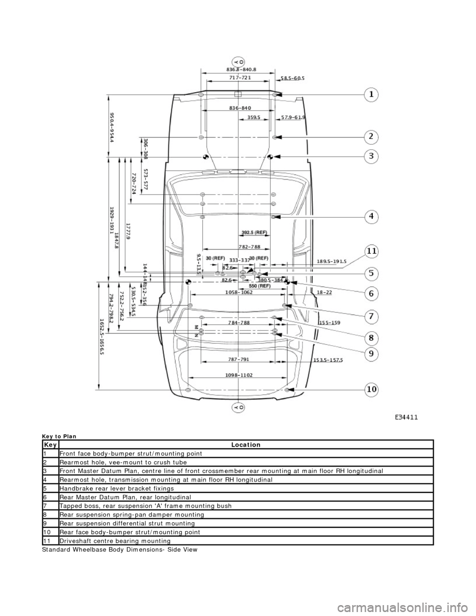
Key to Plan
Standard Wheelbase Body Dimensions- Side View
KeyLocation
1Front face body-bumper strut/mounting point
2Rearmost hole, vee-mount to crush tube
3Front Master Datum Plan, centre li ne of front crossmember rear mount ing at main floor RH longitudinal
4Rearmost hole, transmission mounting at main floor RH longitudinal
5Handbrake rear lever bracket fixings
6Rear Master Datum Plan, rear longitudinal
7Tapped boss, rear suspension 'A' frame mounting bush
8Rear suspension spring-pan damper mounting
9Rear suspension differential strut mounting
10Rear face body-bumper strut/mounting point
11Driveshaft centre bearing mounting
Page 2388 of 2490
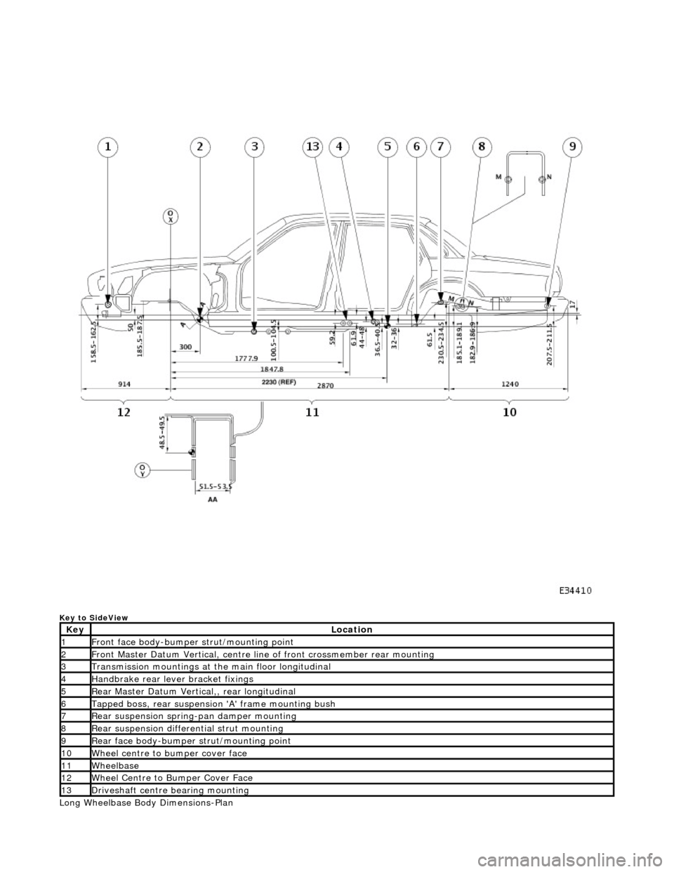
Key to SideView
Long Wheelbase Body Dimensions-Plan
KeyLocation
1Front face body-bumper strut/mounting point
2Front Master Datum Vertical, centre line of front crossmember rear mounting
3Transmission mountings at the main floor longitudinal
4Handbrake rear lever bracket fixings
5Rear Master Datum Vertical,, rear longitudinal
6Tapped boss, rear suspensi on 'A' frame mounting bush
7Rear suspension spring-pan damper mounting
8Rear suspension differential strut mounting
9Rear face body-bumper strut/mounting point
10Wheel centre to bumper cover face
11Wheelbase
12Wheel Centre to Bumper Cover Face
13Driveshaft centre bearing mounting